Semi-fixed (spring) fixities allow you to model a member end fixity that is somewhere between that of a truss (pinned) fixity or frame (fixed) fixity.
This article goes into the detail of semi-fixed members, how to set them in S3D, how their values are used in the software, and their effect on member behaviour.
Frame, truss and semi-fixed member end fixities
First, a quick recap of Frame vs Truss fixities:
- A Frame fixity (FFFFFF), also referred to as “fixed” or “fully fixed”, ensures there is no rotation between connected members at joints, and all moments are transferred from one member to the other
- A Truss fixity (FFFFRR), also referred to as “free” or “pinned”, allows connected members to rotate relative to each other, meaning no moments are transferred, and ensuring the member end moment is zero
It should be noted too, that frame and truss connections are really idealisations, since they are difficult, if not impossible, to achieve in real-world structures.
A semi-fixed member-end fixity, also referred to as a “spring” or “flexible” fixity, offers something in-between these two cases – some rotation between members is allowed at the node, but the members are not completely free to rotate relative to each other. This gives some moment at the end of the member, but, with an appropriate spring stiffness, less moment than the frame fixity, and a greater moment than the truss fixity.
Semi-fixed members therefore offer a model which is closer to that of the real-world structure, rather than the idealised cases of frame or truss connections.
How to set semi-fixed fixities in S3D
Semi-fixed fixities are set from the left hand menu in S3D, when a member is selected.
Selecting “Semi” from the buttons at the top of the left hand pane will set the fixity code to FFFFSS at both ends of the member, and open the fields Node A rotational stiffness Y (RyA), Node A rotational stiffness Z (RzA), Node B rotational stiffness Y (RyB), and Node B rotational stiffness Z (RzB) for editing:
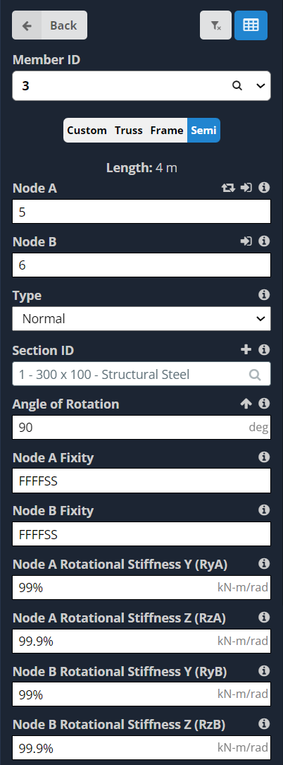
(Note you can also choose the “Custom” option, and then manually adjust the fixity code to use an S instead of F or R to achieve the same result).
You can then set the spring stiffness for each of the 4 fields RyA, RzA, RyB & RzB.
Setting the spring stiffness directly
You can specify the spring stiffness, in the units shown in the entry box, by typing the number in directly:
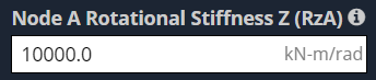
A rotational spring with stiffness of 10 000 kNm/rad will then be used at the end of the member.
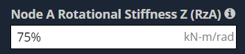
Setting the spring stiffness as a percentage
You can also specify the spring stiffness as a proportion of the member stiffness, by adding a % sign at the end of the number, e.g. 75%:
The absolute spring stiffness is then calculated by taking the percentage, expressed as a decimal value, as the factor ‘r’ in the following equation:
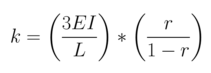
Where:
- E is the Young’s Modulus
- I is the moment of inertia about the relevant axis
- L is the length of the member
E.g. 75% is expressed as 0.75, giving k = 3EI/L * (0.75/(1-0.75)) = 3EI/L*3 = 9EI/L.
Comparison of semi-fixed members with fixed and truss members
Now that we know how to set a member to semi-fixed, and enter the spring stiffness, Let’s take a look at an S3D model that compares the behavior.
The image below shows an S3D model with several instances of the same member, each with a different fixity and spring stiffness:
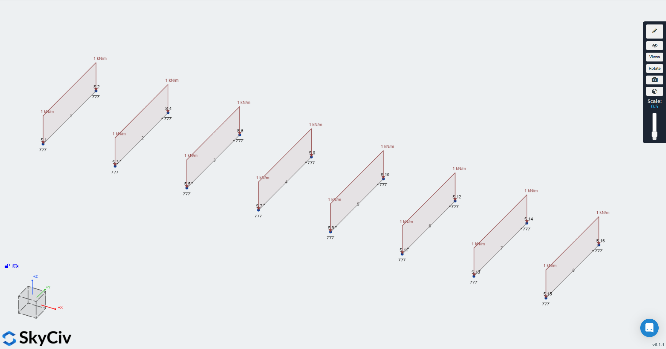
(The model can be accessed at this link platform.skyciv.com/structural-viewer/semi-fixed-members)
Each member has a rectangular cross-section of 100 x 300 mm, giving a moment of inertia (I) of 225.0E6 mm^4. The members are 4.0 m in length, and use the General Structural Steel material, which has a Young’s modulus of E = 200.0E3 GPa (N/mm2). The value of 3EI/L for each of the members is therefore 33750.0 kN-m/rad.
The supports at the end of the members are all fully fixed (encastre). The 8 members each have progressively less stiffness, starting with a Fixed member, then moving onto a very high spring value, equal to 297 EI/L, then going down to a spring value of EI/L /99. The final member is set as a Truss member. The stiffnesses of the members are shown in the table below:
|
Member |
Fixity | r | multiplier for 3EI/L | Spring Stiffness
(algebraic) |
Spring Stiffness
(kN-m/rad) |
|
1 |
Frame | – | infinite | infinite | infinite |
|
2 |
Spring (set value,
same as 99%) |
– | – | – |
3341250.0 |
|
3 |
Spring 99% | 0.99 | 0.99/(1 – 0.99) = 99 | 297 EI/L |
3341250.0 |
| 4 | Spring 75% | 0.75 | 0.75/(1 – 0.75) = 3 | 9 EI/L |
101250.0 |
|
5 |
Spring 50% | 0.50 | 0.5/(1 – 0.5) = 1 | 3 EI/L |
33750.0 |
|
6 |
Spring 25% | 0.25 | 0.25/(1 – 0.25) = 1/3 | EI/L |
11250.0 |
| 7 | Spring 1% | 0.01 | 0.01/(1 – 0.01) = 1/99 | (1/99) EI/L |
340.9 |
| 8 | Truss | – | 0 | 0 |
0.0 |
Solving the model, we can see the difference in the bending moment diagrams:
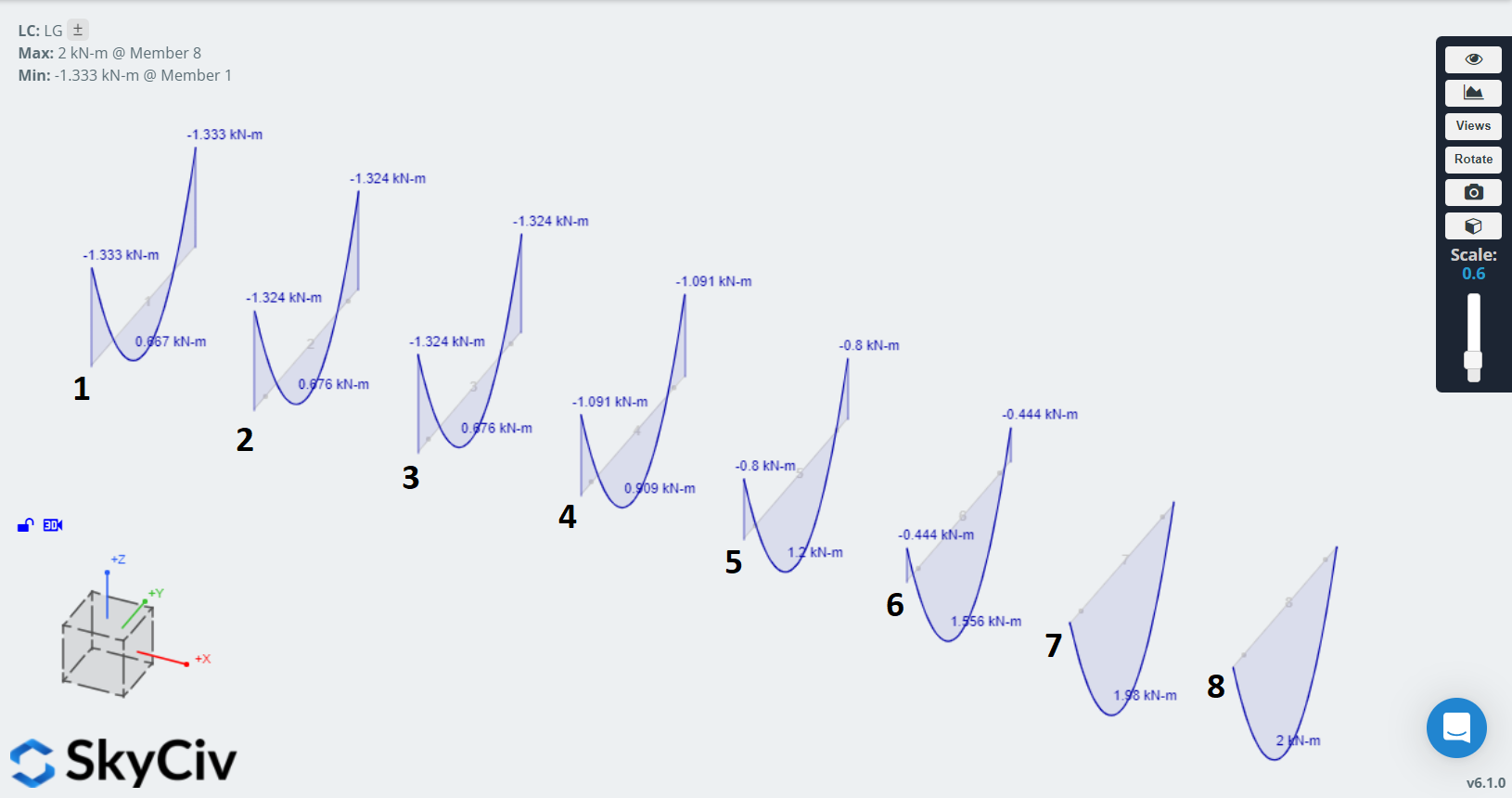
For the frame member on the left, we see the expected combination of hogging near the supports and sagging in the middle of the member, with a point of zero moment either side of the midpoint of the member. On the right hand side, we see the truss member experiences sagging only, as expected.
For the semi-fixed members, as their stiffness reduces, they have smaller regions of hogging, smaller (in absolute terms) values of hogging moment, and greater values of sagging moment. A very high spring stiffness gives results very similar to those of the frame fixity, and a very low spring stiffness gives results very similar to those of the truss fixity.
The deflections of the members vary similarly:
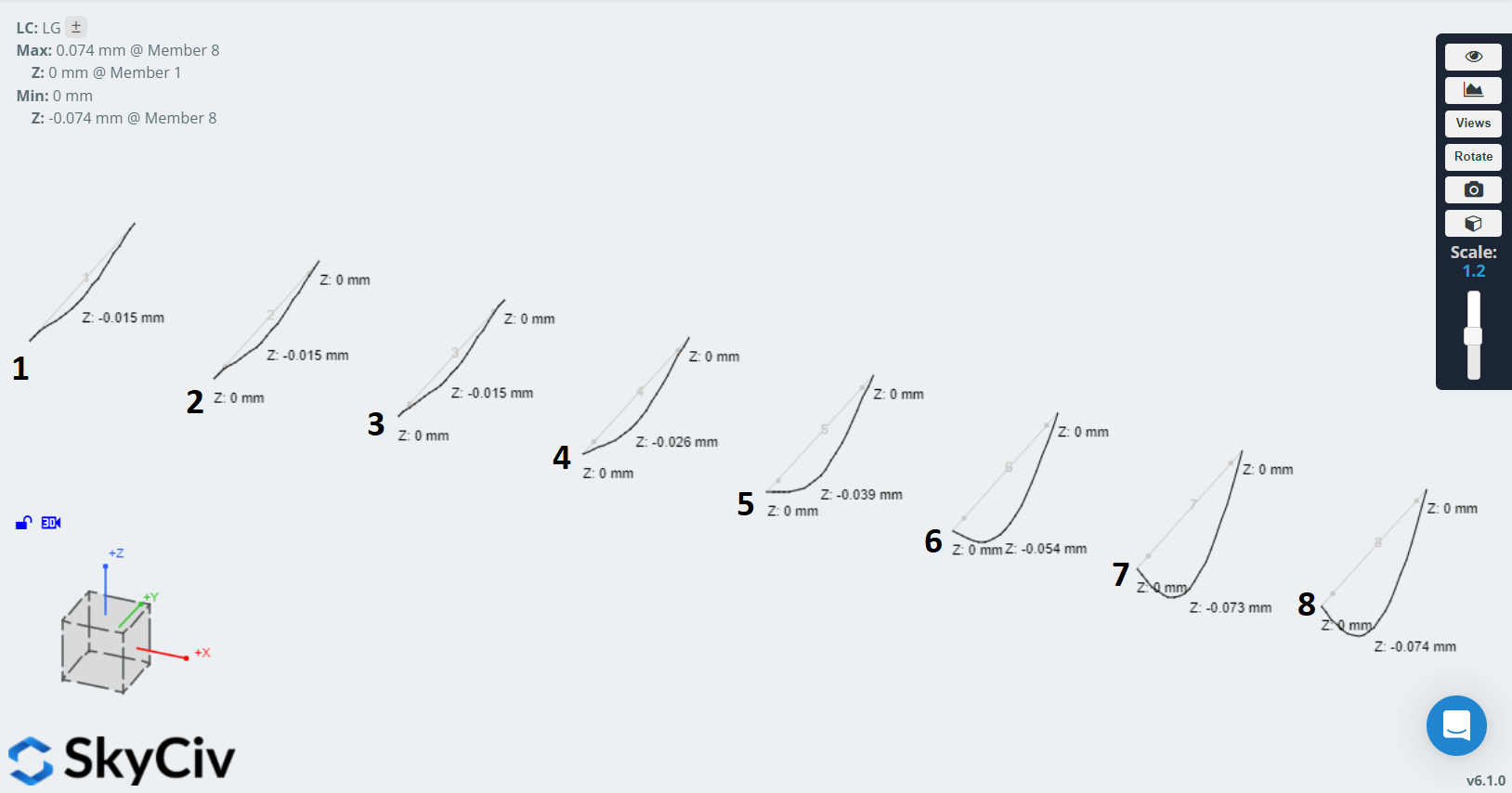
For the fully fixed member (no. 1) we see the expected deflection with points of inflection either side of the midpoint of the member. For the truss member we see the deflection is greater and there are no points of inflection.
For the semi-rigid members, as their spring stiffnesses reduce, they see greater deflection and the deflected shape becomes more similar to that of the truss case. The results are tabulated below:
| Member | Fixity | r | Spring Stiffness
(kN-m/rad) |
End Moment
(kNm) |
Midpoint
moment (kNm) |
Midpoint deflection (mm) |
|
1 |
Frame | – | – | -1.333 | 0.677 |
0.015 |
|
2 |
Spring (set value,
same as 99%) |
– | – | -1.324 | 0.676 |
0.015 |
|
3 |
Spring 99% | 0.99 | 3341250.0 | -1.324 | 0.676 |
0.015 |
|
4 |
Spring 75% | 0.75 | 101250.0 | -1.091 | 0.909 |
0.026 |
|
5 |
Spring 50% | 0.50 | 33750.0 | -0.800 | 1.200 |
0.039 |
|
6 |
Spring 25% | 0.25 | 11250.0 | -0.444 | 1.556 |
0.054 |
|
7 |
Spring 1% | 0.01 | 340.9 | 0.000 | 1.980 |
0.073 |
|
8 |
Truss | 0 | 0.0 | 0.000 | 2.000 |
0.074 |
In summary
- Semi-fixed members result in behaviour somewhere between that of a fixed or pinned connection
- You can set the spring stiffness for a semi-fixed member as an absolute or relative value
- Then using a relative stiffness, the calculated absolute stiffness is inversely proportional to the r factor, the r factor being the percentage fixity expressed as a decimal
- A higher spring stiffness gives behaviour closer to that of a frame member, a lower spring stiffnesses gives behaviour closer to that of a truss member
New to SkyCiv? Sign up for a free account at: http://www.skyciv.com/free-signup