Using the SkyCiv Load Generator in EN 1991-1-4 Wind Load Calculations
To calculate the wind load pressures for a structure using SkyCiv Load Generator, the process is to define first the code reference. From there, the workflow is to define the parameters in Project Tab, Site Tab, and Building Tab, respectively. However, free users can only use the calculation for a gable and open pitched/duopitched roof for a maximum of 3 solves per week. With a Professional Account or by purchasing the standalone Load Generator module, you can use all the features of this calculation as long as you want You can purchase the standalone module thru this link.
The supported countries for EN 1991-1-4 calculation in this module are as follows:
- Belgium
- Czech Republic
- Denmark
- Finland
- France and French territories
- Germany
- Greece
- Ireland
- Italy
- Luxembourg
- The Netherlands
- Poland
- Portugal
- Romania
- San Marino
- Singapore
- Slovakia
- Slovenia
- United Kingdom
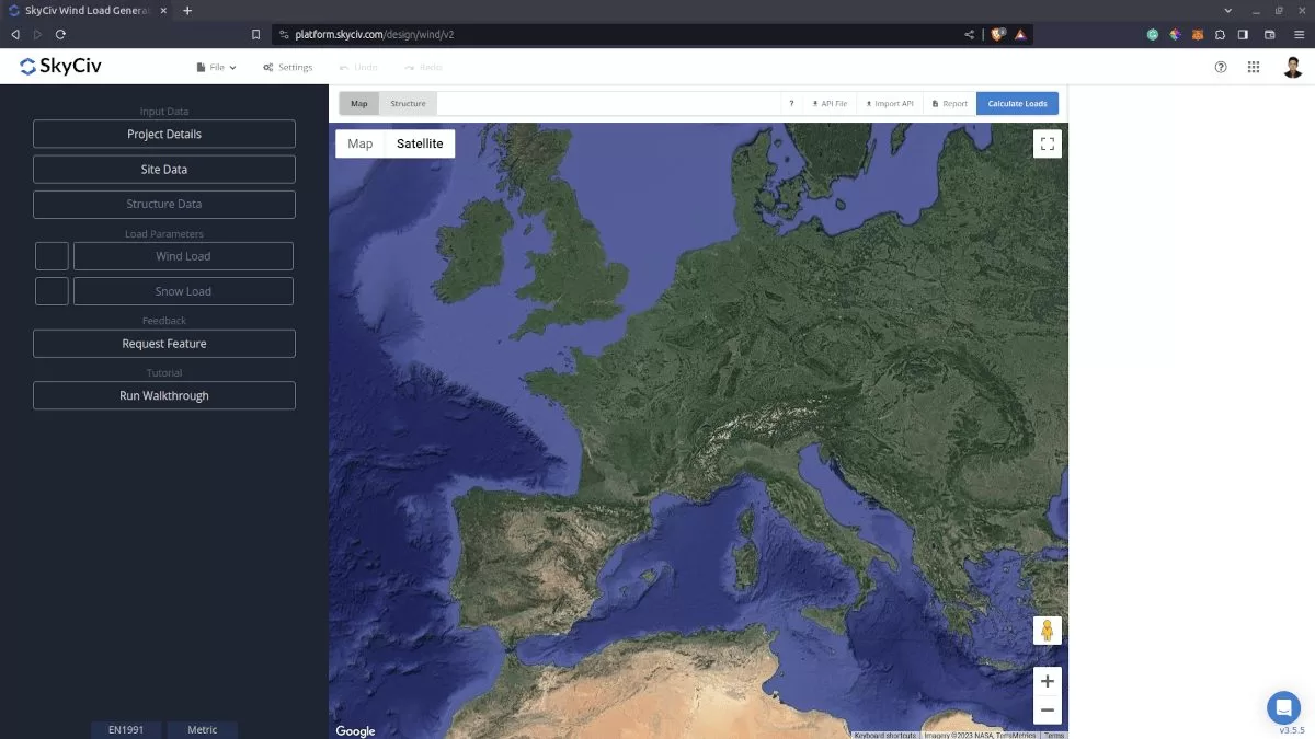
Figure 1. SkyCiv Load Generator UI.
Site Data
Users can get the wind speed by location any time from the SkyCiv free wind speed map database. Using EN 1991-1-4, you just need to put the address of the structure located in any of the supported countries. The necessary parameters will show according to National Annex governing the structure location. In order to explain it further, we will use London, UK as the arbitrary address. You can also override the basic wind speed to get a more appropriate design wind pressure.
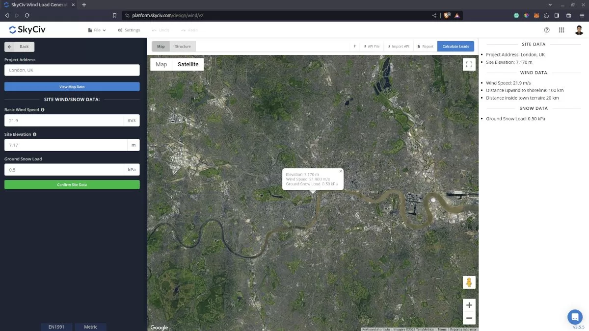
Figure 2. Site data of SkyCiv Load Generator.
SkyCiv has digitalized the map as per the paperback standard. This means, you can simply enter in the site location and the software will automatically pull the wind speeds based on this input. The software will use our internal interpolator to calculate values between the contours, to ensure accurate wind speeds are used in your designs.
Site Input Parameters for Wind Load Calculation
Project Address – Used for getting the nearest wind speed based on the wind region and country
Basic Wind Speed – the fundamental basic wind speed to be used in calculating the design wind pressure. This is automatically determined based on Project Address and can be modified by the user
Site Elevation – if required by the National Annex, used in calculating the altitude factor calt
Once the parameters above are completed, we can now proceed to the Structure Data section.
Structure Data
The structure data and the wind and snow parameters are separated into different sections. You need to defi ne first the Structure you are analyzing. Right now, the available structures for EN 1991 are as follows:
- Building – supports the following roof profile:
- Duopitch, Hip, Monopitch
- Open Duopitch, Open Monoslope
- Signboard
- Poles
In this documentation, we will focus on building structure.
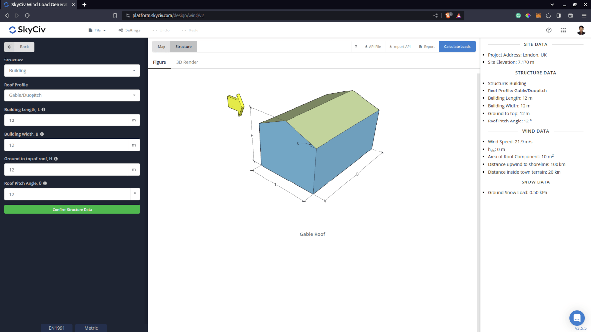
For building structure, we need to fill the structure dimensions as shown in the building figure above. The option for the roof profiles are as follows:
- Gable/Duopich
- Monoslope/Monopitch
- Hip
- Pitched (open duopitch)
- Open Monoslope
For free users, only Gable and Pitched roof are available for Building. Once you have completed all the structure data inputs, you can visualize the structure by clicking the 3D Render at the right side. In addition, note that the building length is defined as the dimension parallel to the wind direction (as shown in arrow) and the building length is perpendicular to the wind direction
Structure Input Parameters for Wind Load Calculation
Roof Profile – Used in pressure coefficient values based on the selected roof profile and roof pitch angle
Building Length – the dimension parallel to the wind direction as defined in EN 1991-1-4. Used in calculation of pressure coefficients
Building Width – the dimension perpendicular to the wind direction as defined in EN 1991-1-4. Used in calculation of pressure coefficients
Ground to top of roof Height – the dimension of the structure from ground to the roof apex. Used in calculation of velocity pressure
Roof Pitch Angle – the roof slope in degree. Used in calculation of pressure coefficients
Once the parameters above are completed, we can now proceed to the Wind Load Parameters section.
Wind Data
To proceed with our wind load calculation, we need to check the checkbox first beside the Wind Load button. By default, this is checked when the site wind data has been defined.
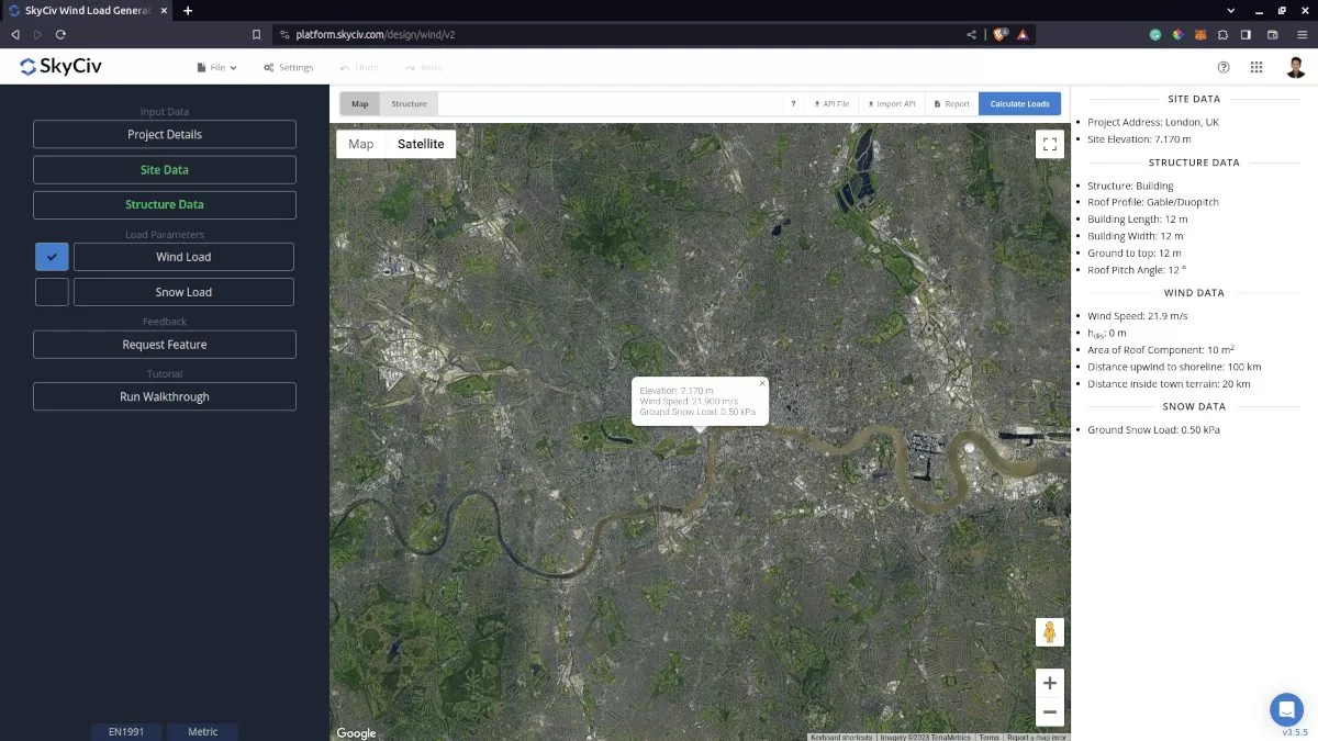
Figure 4. Checkbox for Wind Load Data.
The next step, is to define the Wind Source Direction. This parameter is used in obtaining the upwind (left side) and downwind (right side) ground elevations to calculate for Orography Factor, co and Direction Factor, cdir represented by a 30-degree sector.
Topography Input Parameters
Wind Source Direction – used in obtaining the upwind (left side) and downwind (right side) ground elevations to calculate for Orography Factor, co and Direction Factor, cdir
Terrain Category – Used in calculation of Roughness Factor cr. Assumed to be homogeneous for each wind source direction
Season/Month – Used in determining the Season Factor . Required for Belgium, Ireland, and United Kingdom
Type of Terrain – Options to select Flat, Hill, Escarpment, Ridge
H – Height of obstruction/terrain. For type of terrain is set to option other than Flat terrain, this is used in calculating the Orography Factor, co
Lu – Horizontal distance from upwind base of the obstruction to its peak. For type of terrain is set to option other than Flat terrain, this is used in calculating the Orography Factor, co
Ld – Horizontal distance from peak of the obstruction to the downwind base. For type of terrain is set to option other than Flat terrain, this is used in calculating the Orography Factor, co
x – Horizontal distance of structure to the peak of the obstruction with the peak as the point of reference. For type of terrain is set to option other than Flat terrain, this is used in calculating the Orography Factor, co
Distance upwind to Shoreline – (for BS/IS EN 1991-1-4) used in calculating the Roughness Factor cr
Distance inside Town terrain – (for BS/IS EN 1991-1-4) used in calculating the Roughness Factor cr
Displacement Height – (for BS/IS EN 1991-1-4) used in calculating the Roughness Factor cr
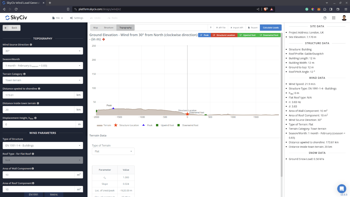
Figure 5. Elevation Data from Google Maps for upwind (left) and downwind side (right).
Wind Input Parameters
Type of Structure – Required to be set to EN 1991 Buildings for duopitch, monopitch and hip roof; and EN 1991 Canopy Roof for open duopitch and open monoslope
Roof Type – for Flat Roof – (For duopitch, monopitch and hip roof) Only applicable for duopitch, monopitch and hip roof with roof pitch angle less than 5 degrees. Options to be defined are the Parapet height, Radius of Curved Eaves, Angle of Mansard Eaves depending onthe selected Flat Roof type
Area of Wall Component – used in calculation of the external pressure coefficient cpe
Area of Roof Component – used in calculation of the external pressure coefficient cpe
Natural Frequency of structure, n – Approximate formula equal to 46/h as per Equation F.2 of EN 1991-1-4. Used in calculating the Dynamic Factor cd
Total Logarithmic Decrement of Damping – Used in calculating the Dynamic Factor cd
Floor Elevation – Since the wind pressure acting on the windward is parabolic in nature, this is used to approximate this pressure by assigning multiple rectangular pressure acting on the wall in between the level
After all these parameters are defined, the next step is to click the Calculate Loads on the upper right side of the UI.
Results
Once all the parameters are defined, clicking the Calculate Loads button will give a result as shown below:
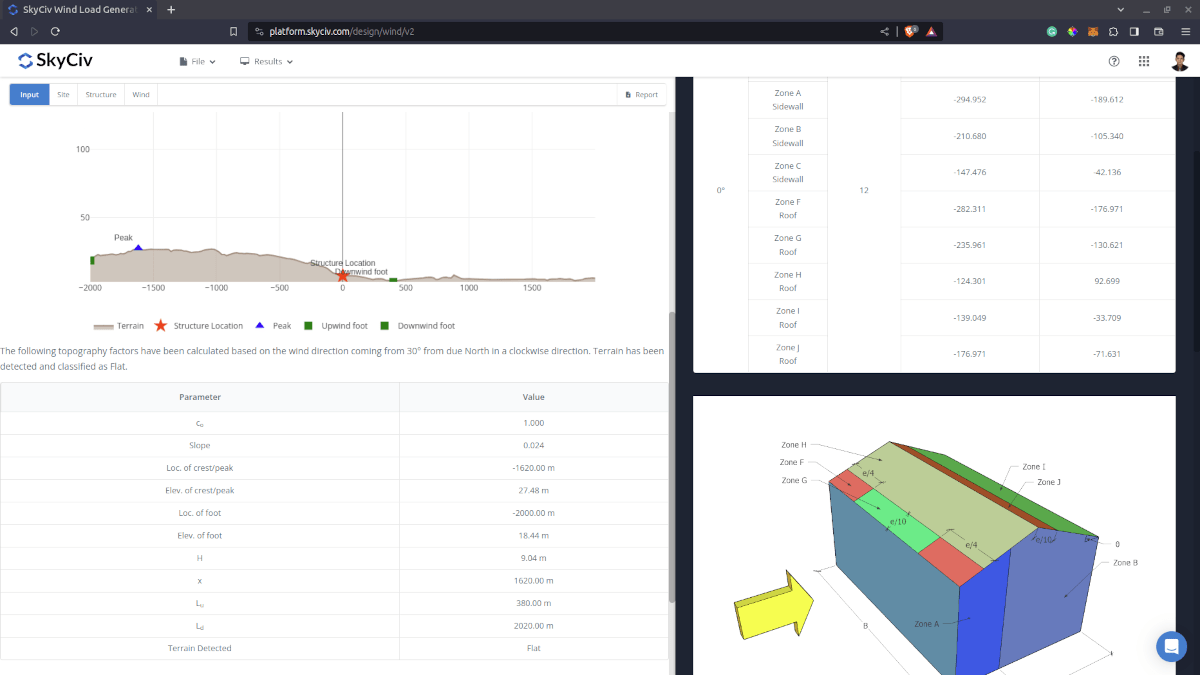
Figure 6. Wind results for Building
The summarized results are shown on the right side of the screen. Other results are shown on the detailed report that can be used to countercheck the calculated pressures.
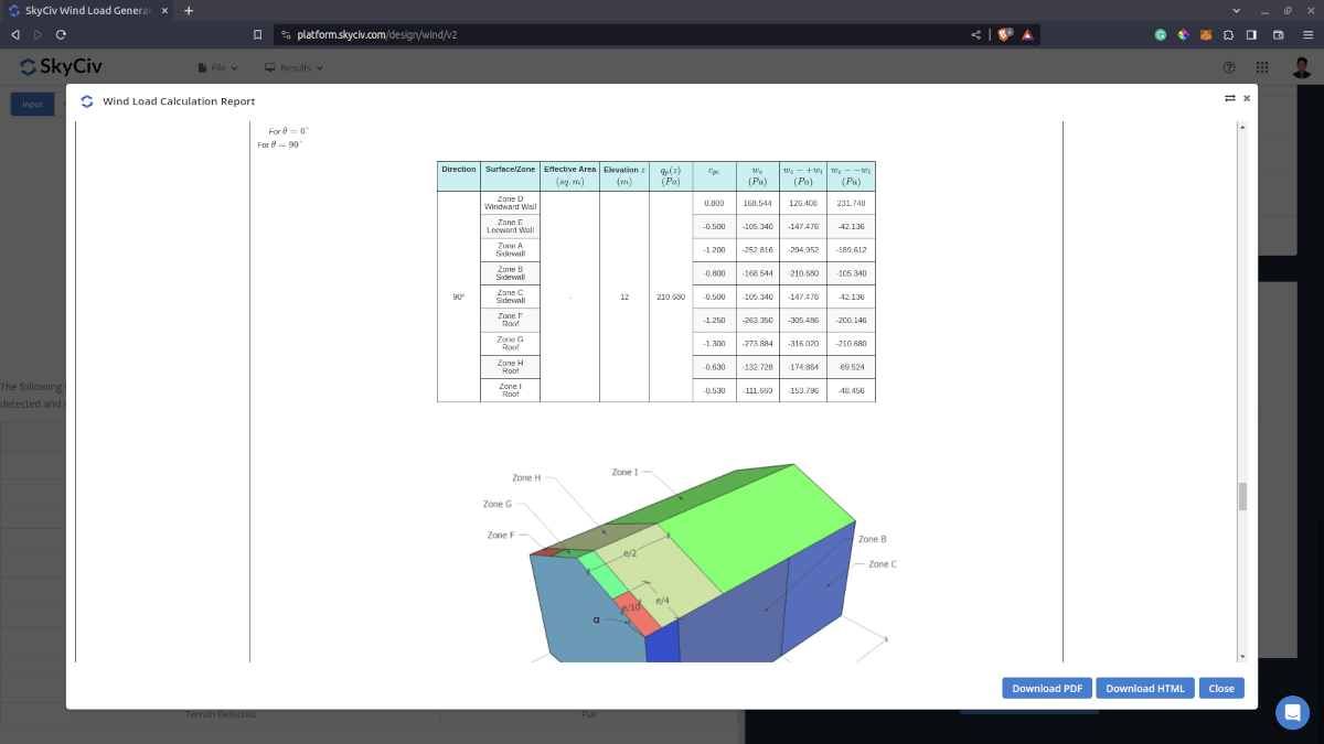
Detailed Calculation
The detailed wind load calculations can be accessed only by Professional account users and those who purchased the standalone load generator module. All the parameters and assumptions used in the calculation are displayed on the report to make it transparent to the user. You can download a sample detailed calculation thru the following links:
EN 1991 Building
EN 1991 Canopy Roof
For additional resources, you can use these links for reference: