Reinforced Concrete (RC) Design Manual (AS 3600, EN 2, ACI 318)
Details
Once the user has chosen the desired design code, the user will be presented with the “Details” tab as shown in the figure below. The units will be chosen automatically by program based on the chosen design code (AS 3600/EN 2 – metric and ACI 318 – imperial).
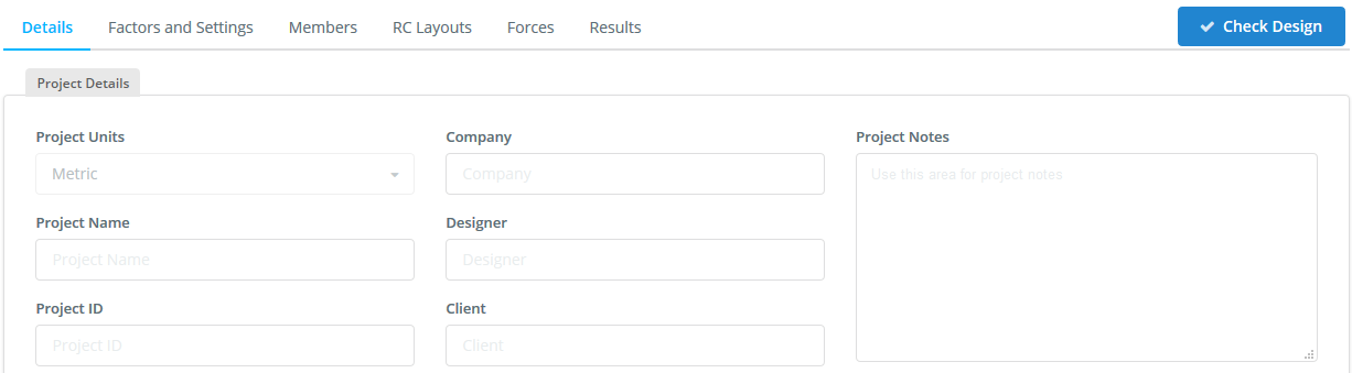
- A Project Name;
- A Project ID;
- Your Company Name;
- The Designer;
- The Client; and
- Any other notes you would like to include
This information will be inserted into the generated design report.
Factors and Settings
- Assume the neutral axis depth, x (initial value d – efective depth)
- Calculate concrete compression force, steel tension and compression force
- Check equilibrium of force components
- The above procedure will be repeated while the sum of compression forces is not equal to tension forces
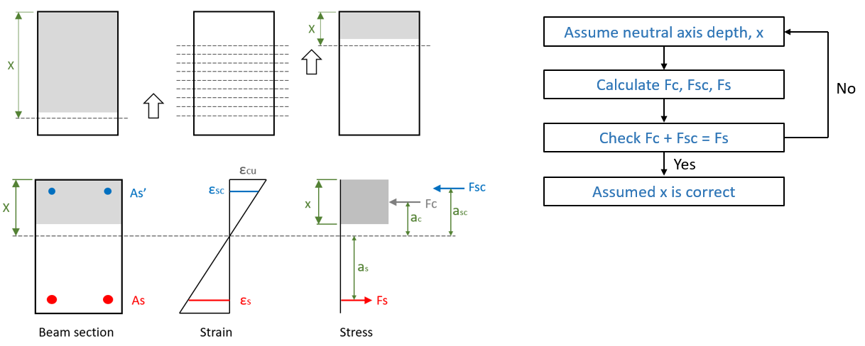
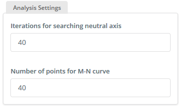
Also, the iterative procedure is used for the calculation of neutral axis depth in case of serviceability limit state, where the triangle shape of compressed concrete is used. Generally 40 iterations is enough. Ultimate flexure is calculated as Mult = Fc ∙ ac + Fcs ∙ acs + Fs ∙ as. Detailed information about the calculations are described in output design report.
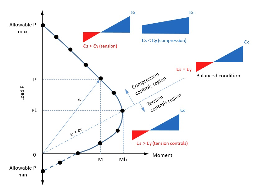
When user has to deal with the designing of column members, in case of acting of axial force with flexure, the design module considers the N-M interaction curve. To consider this curve internally program needs the necessary number of intermediate points. Typically there are three main points: maximum axial tension, maximum axial compression and balanced condition. Then intermediate points are considered from balanced condition to maximum tension and from balanced condition to maximum compression. By default, the program considers 40 points, although the user has the freedom to edit this.
In the case of axial force with biaxial flexure the program considers 3D N-Mx-My interaction surfaces based on “Bresler Load Contour Method”. The program considers a set of M-N curves separately and then by the load contour method generates 3D surfaces. Detailed information about these calculations are described in output design report.
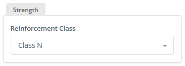
In the case of the AS 3600 design code, the reinforcement class must be selected. This will be reflected in the calculation of the strength reduction factor φ
Members
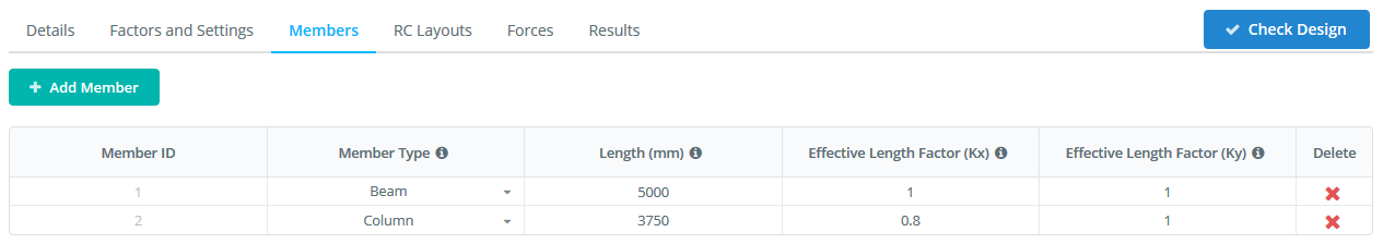
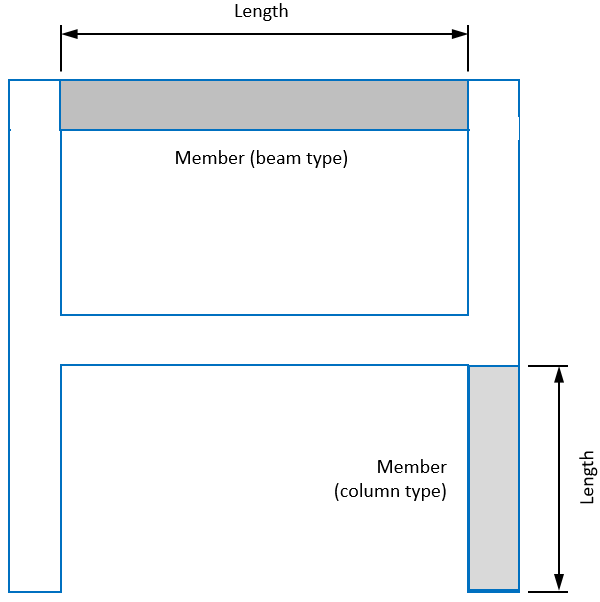
In the Standalone module, the user is able to define the desired number of members, which can be established with beam or column type. For each member the clear length must be defined. If the member is a column type, an additional input is needed for the effective length.
In the SkyCiv Beam software, where only beam type members are considered, the user has to input the typical deflection coefficient. This coefficient will be used for the calculation of the beam deflection with crack opening in section.
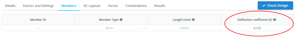
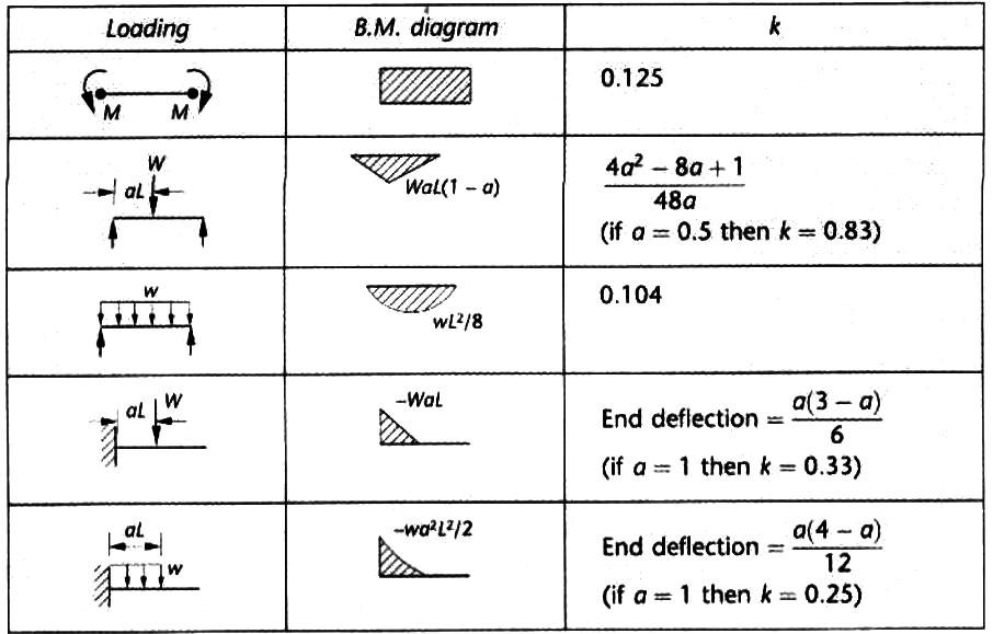
Shown below are some examples of typical deflection coefficients that represent different cases of beam flexure.
RC Layouts
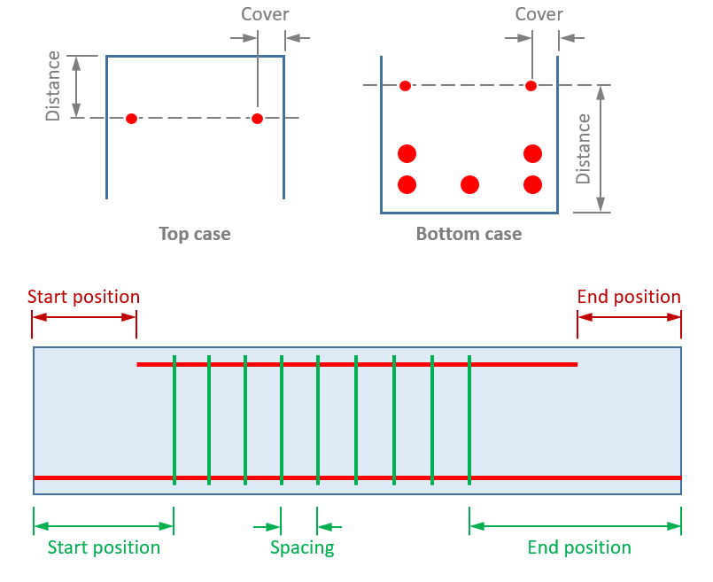
For each member to be designed the section type, material properties and reinforcement, must be defined. For the section, the section type must be chosen and its dimensions defined. For the reinforcements, the longitudinal and shear reinforcement (stirrups) must be defined. The user is able to arrange rebars at any longitudinal and transverse position inside the member. If shear reinforcement is not defined during the section design check, the program will consider shear capacity with only longitudinal reinforcement. Lastly, the material strength properties for concrete and steel, as well as limited crack width, must be defined.
Once all the data is defined for the member, the user must process to save the configuration by clicking the “Save” button. This is necessary for the RC layout to be applied, otherwise, they will not be saved for design check.
Forces
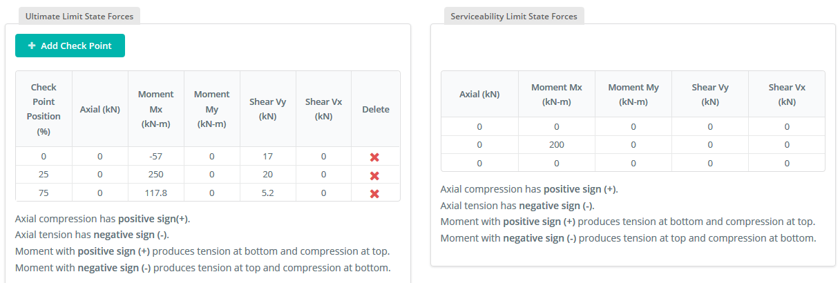
For the standalone version of this module, the forces are defined manually in tables. Below are two tables: one is for forces that will be considered for ultimate limit state checks and the other for serviceability limit state checks. The forces are defined for each section of the member and the number of sections along the member is not limited. Clicking on the “Add New Point” button allows the user to define the position (as a % of length along the member) and the set of forces acting on that location along the member.
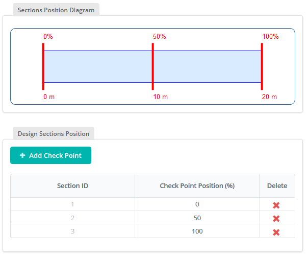
In the SkyCiv Beam, the forces are defined automatically based on the beam analysis performed by the module. In this case, the user may just define the desired number of sections to be designed and specify their positions along the member.
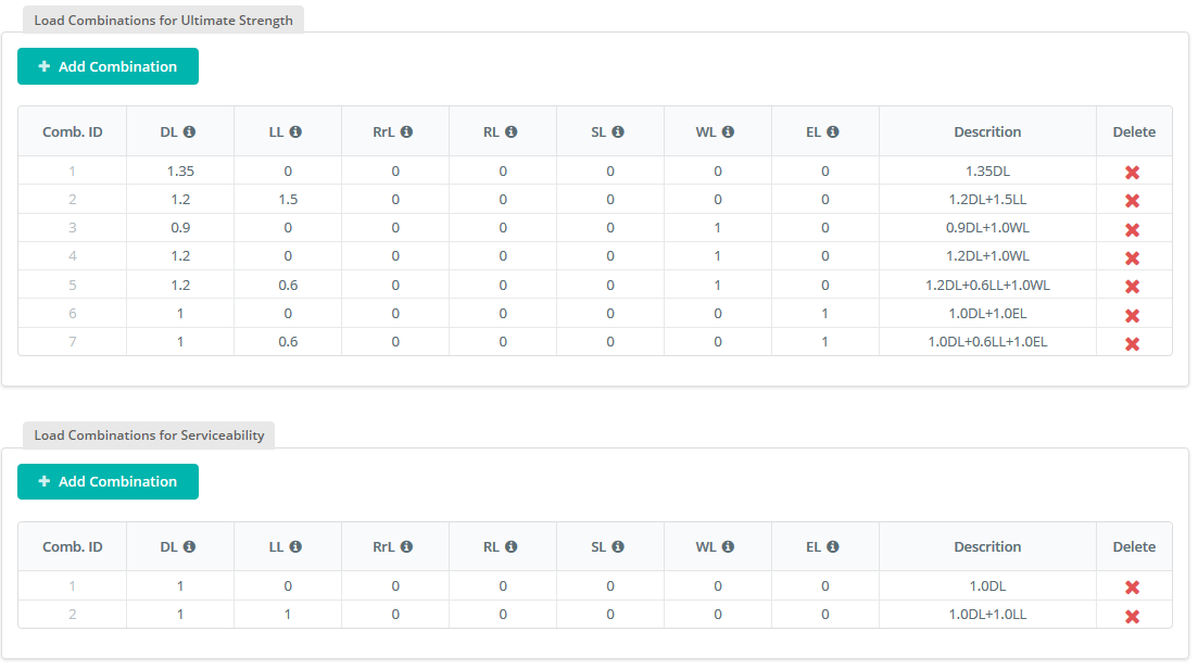
Combinations
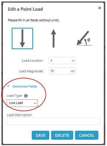
If the user wants to consider load combinations, he/she must define the load type for each load that is applied to the beam model.
In the Combinations tab, the user can define all the necessary load combinations for strength and serviceability checks. By default, the program generates a set of standard load combinations based on the chosen design code. They can be edited and extended by the user. In particular load combination, a value not equal to zero must be inputted for a specific load type to be considered. Otherwise, the load type will not be considered in the combination at all.
Once the table is completed or has been properly filled by the user, it is necessary to save the work by clicking the “Save” button.
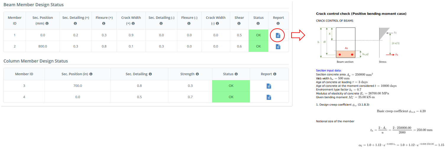
Results
After completing all the necessary information for the design of the concrete member, the user can finally proceed with the design by clicking the “Check Design” button. In the Results tab, the user may view the design checks and capacity ratios. In the design module, there are capacity ratios for each separate checks like flexure check, shear force check, crack control and etc. For a more in-depth look at the design computation, clicking the report-icon at the end of the row will generate a detailed design report of the checks performed by the module. The report includes all check formulas with all the described parameters and detailed hand calculations in relation to the design of the reinforced concrete section.