ORTHOTROPIC MATERIALS
Before going through an explanation of orthotropic plates, let’s look at some examples of orthotropic materials. Materials such as crystals of topaz and barite are orthotropic (Chandrupatla, 2012). Another very common orthotropic material is wood. Figure 1 shows the principal axes in which mechanical properties are defined for wood.
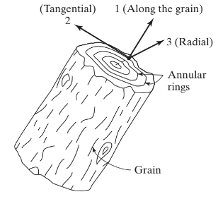
Figure 1. Wood as an orthotropic material (Chandrupatla & Belegundu ,2012, page 233)
Axis 1 is defined along the grain or fibers; axis 2 is tangential and axis 3 runs radially. The generalized Hooke’s law for this example (and for any other orthotropic material) can be written as
Equations 1. Generalized Hooke’s Law (Chandrupatla & Belegundu,2012, page 233)
Where:
- ε1, ε2, ε3 are the normal strains.
- γ12, γ13, γ23 are the shear strains.
- E1, E2, and E3 are the Young’s modulus along the principal axis.
- G12, G13, G23 are the shear modulus.
- ν21, ν31, ν12, ν32, ν23 are the Poisson’s ratios.
- For combined indices, the first number indicates where stress is applied and the second where deformation occurs.
Therefore, the main difference in an orthotropic material is we have different mechanical properties along the principal axes, that is, “x”, “y”, “z”.
ORTHOTROPIC PLATES
There are some common use cases for plates in structural engineering, that we can summarize as follows: isotropic flat, composite or sandwich and stiffened (W.Jiang et al, 1997).
Isotropic flat plates are regular plates (figure no.2), it is only needed to define a one value for Poisson’s ratio, Young, and shear modulus because the mechanical properties in any direction do not change.
Figure no.2. Flat plates are commonly isotropic (W.Jiang et al, 1997, page 106)
For the two last options, sandwich and stiffened plates (figure no.3), we have to define different mechanical properties in their principal axis. These different values make plates orthotropic.
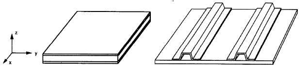
Figure 3. Composite (left) and hat-stiffened plates (right) (W.Jiang et al, 1997, page 106)
In an orthotropic plate, we would have two axes with the same stiffness, figure no.3. Axes “x” and “y” lie on a plane, and “z” is perpendicular to it.
We can say that (W.Jiang et al, 1997):
- Ex = Ey ≠ Ez ; (Ex, Ey )> Ez .
- νxz = νyz ≠ νxy ; (νxz, νyz) >νxy
- Gxy = Gxz = Gyz
The expressions indicated before implies that stiffness in the “x” and “y” directions are higher than “z”. The Poisson’s ratios also show there is more deformation in planes related to the “z” direction than in a plane formed by the “x” and “y” axis.
EXAMPLE
Description and Set up
To summarize the concepts learned in past sections, we are going to develop an example in SkyCiv. It consists of the analysis of a sandwich wall/slab panel which is built with two shotcrete layers separated by a polystyrene core. We have chosen the next reference for the mechanical properties to be used in modeling: Torres Villavicencio et al. (2013).
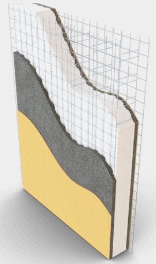
Figure 4. Sandwich Wall/Slab Panel
To capture the difference of analysis in plates when we select the advanced options (orthotropic), we develop a short comparison of the panel sandwich described above and an approximation in their mechanical properties using an isotropic approach. The latest case uses values in mechanical properties that do not change along their principal axes.
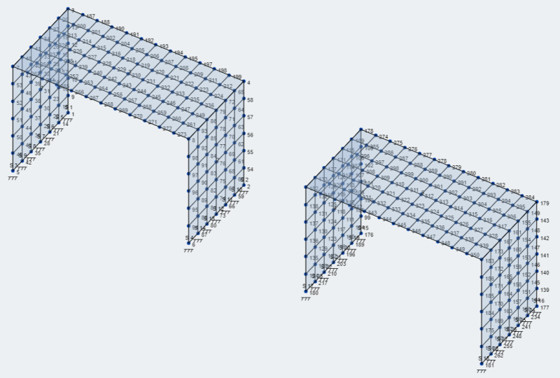
The goal of this expample is to compare the results in terms of vertical displacement. The model setup is shown in Figure 5.
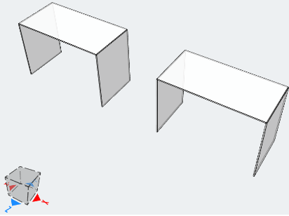 Figure 5. Model setup. Orthotropic (left), Isotropic (right)
Mechanical properties
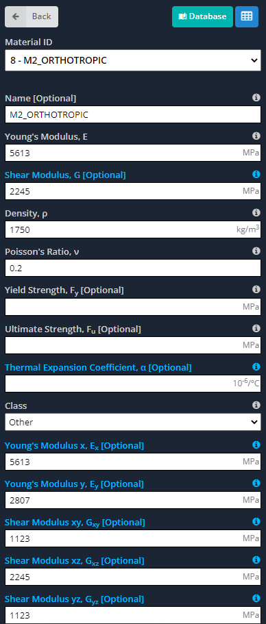
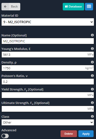
Based on different laboratory tests reports, the orthotropic properties of the panel are (Torres Villavicencio et al, 2013):
| Property | Value |
|---|---|
| E1 (MPa) | 5613 |
| E2 (MPa) | 5613 |
| E3 (MPa) | 2807 |
| G12 (MPa) | 2245 |
| G23 (MPa) | 1123 |
| G13 (MPa) | 1123 |
| ν12 | 0.2 |
| ν23 | 0.25 |
| ν13 | 0.25 |
Table no.1. Sandwich Panel Orthotropic Mechanical Properties
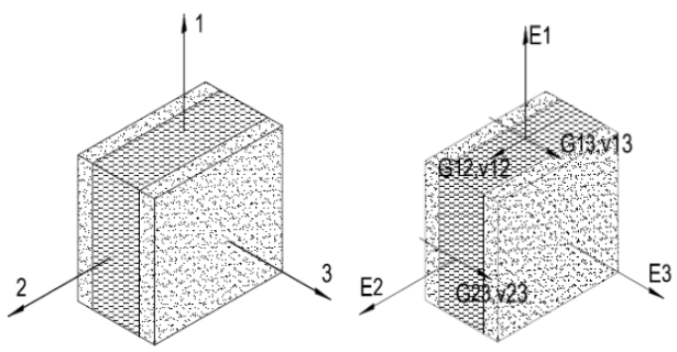
Figure no.6. Principal axes in panel element (Torres Villavicencio et al, 2013).
The approximation for the isotropic case are indicated in the table below.
| Property | Value |
|---|---|
| E (MPa) | 5613 |
| G (MPa) | 2245 |
| ν | 0.20 |
Table no.2. Sandwich Panel Isotropic Mechanical Properties Approximation
Modeling in SkyCiv
We now describe in a very concisely way the steps required to model the example. (For more details in plates modelling, consult this link SkyCiv Plate Modelling). Haven’t tried SkyCiv, follow along using Structural 3D, simply sign up for free here.
- Nodes: To create both cases, we first define the nodes corresponding to the horizontal and vertical plates.

- Materials: As we said before, orthotropic materials have different properties along their principal axes. Next images indicate the inputs we have to define for the model.


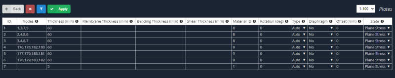
- Plates: Through model nodes we create the rectangular plates. Two for the vertical wall modelling and one for the floor or slab.

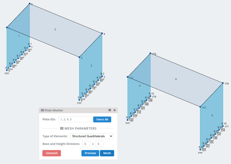
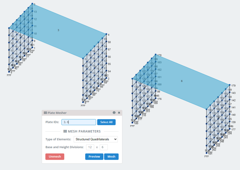
- Meshing plates: SkyCiv has many options to mesh plates and can be consulted in Meshing your plate . For our model let’s use the option of structured quadrilaterals mesh.


- Defining self-weight load case: We’ll only consider this self-weight load to capture the plate general structural behaviour.

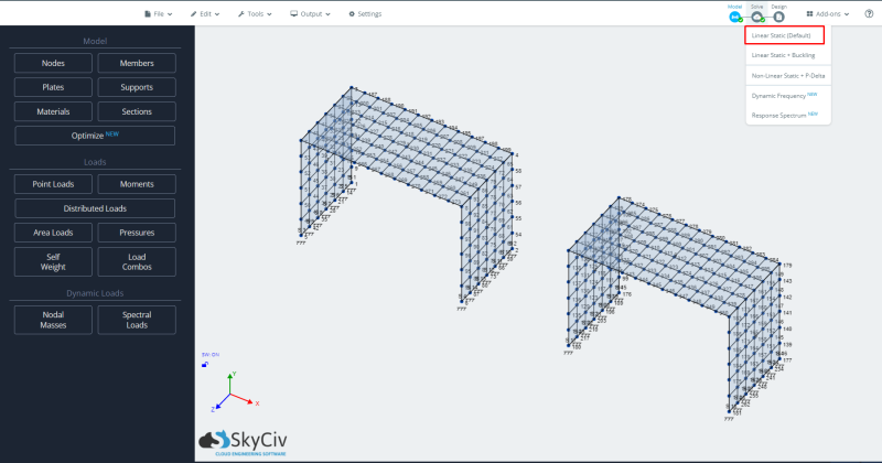
- Running analysis: To run the model we will select the linear static analysis case.

- Results: Finally, at this point we study the structural response for both plates, the isotropic and orthotropic case. For further details in reading results for plate analysis, you can look at this article Plate Analysis Results.


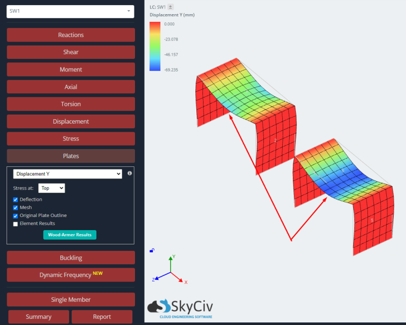
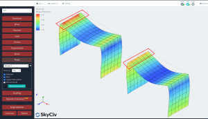
To study the response of both cases, we compare vertical displacement and bending moment results. The orthotropic plate shows smaller deflections and larger bending moments than the isotropic case. We can say that using an orthotropic approach will give us a stiffer element and this will impact the global and local results in an elastic linear analysis.
Get Started for Free
Check out SkyCiv Structural 3D for free today to get a taste of our software!
References:
- Chandrupatla, Tirupathi R & Belegundu, Ashok (2012). “Introduction to Finite Elements in Engineering” 4th edition, Pearson Education.
- W. Jiang et al (1997). “Finite Element Modeling of Stiffened and Unstiffened Orthotropic Plates”, Computers & Structures Vol.63, No.1, pp. 105-117, Elsevier Science Ltd.
- Torres Villavicencio et al (2013). “Trabajo monográfico: Ayudas de Diseño para Sistemas Portantes EMMEDUE de Paneles de Hormigón Armado con Núcleo de E.P.S (Sistema de Poliestireno Expandido)”. Universidad Nacional de Ingeniería.
- All software images taken from SkyCiv Structural 3D Analysis Software