What are the common failures in a boomilever structure, and how to test for them
The Science Olympiad competition is right around the corner! It’s time for teams to gather their designs and review the best performing structures from prior years. This year, we wanted to take a deeper look into the reasons Boomilever’s can fail and what can be done to strengthen your structure.
Designing a Boomilever
Have you modeled a structure in SkyCiv yet? We recommend you start by reading this article first: How to design a Boomilever in SkyCiv. It will show you how to model and design your first structure and simulate your Boomilever’s performance before you build it!
The following article will talk about how to test and analyze your structure, so that you can simulate and find issues in your model ahead of time.
Our Design
The most important part of your design is the way you arrange your members. Are you going to use a Truss? What style of Truss? This will have the highest impact to both your structure’s performance under load and it’s overall weight. It is the single most important decision you’ll have to make.
In this article, we are going to base our design on the following simplified design:
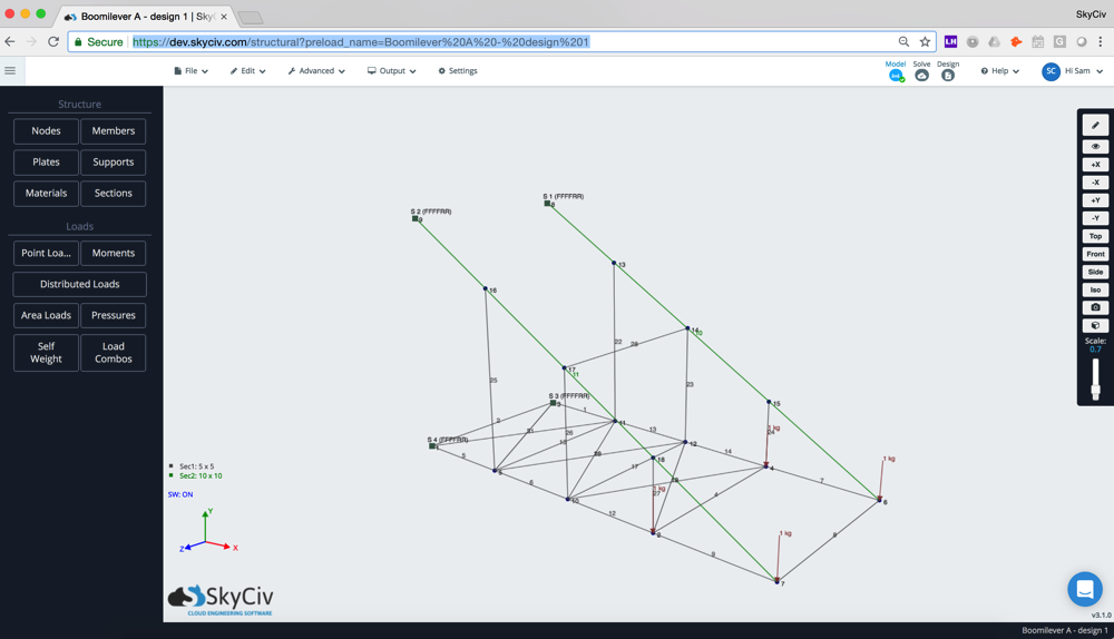
This is comprised of the following elements:

Source: Boomilever Wiki
A: Support/Base
B: Tension Members
C: Distal End
D: Compression Cross Members
Now let’s review to check all the different ways these members can fail, and how we can help strengthen our design.
Failure Cases
Compression Failure
Compression forces are those that compress the member, or crush inwards.
We want to pick a failure criteria we can use. From our article we know that the Compression Failure Stress of Balsa Wood is around 7 MPa. Because wood is an anisotropic material, the strength depends on the quality of the wood and it’s grain direction, but our assumption of failure stress will be a good rule of thumb to use in this design
Our goal is to ensure all compression members have a compression stress no greater than 7 MPa. It is unlikely that the member will fail due to pure compression, but this is important concept to understand and is important for the below checks.
Tension Failure
Tensile forces are those that induce tension within the member, or pull outwards
Balsa wood is twice as strong in tension as it is in compression. It is highly unlikely the structure will fail due to pure tension forces. We can disregard this as a failure criterion.
Failure Checks
1. Bending Stress Failure
We’re going to start with bending stress as it is a common failure case. As the name suggests, this occurs as the member is loaded perpendicular to its Neutral Axis (NA) it will start to bend, causing distribution of stress along the cross-section of the member. An obvious sign of bending occurring, particularly in wood, if the deflection of the member along its span from its original shape.
In our case, all of the wood members are straight before loading, so any deflection tells us that the member is bending. A member experiencing bending stress will look something like this:
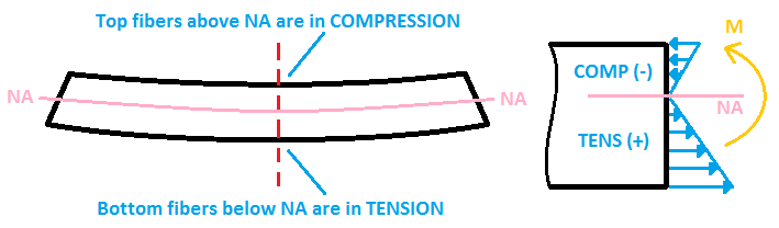
The top of the member is in compression (-) and the bottom (+) are in tension. The “M” is the positive moment force that is inducing the stress distribution in this case.
How to identify Bending Failure
After running the analysis of the Boomilever in Structural 3D, we will operate from the post-processing, or Solve Window. You can use the Visibility Settings on the right side of the screen to prompt some viewing/filtering options.
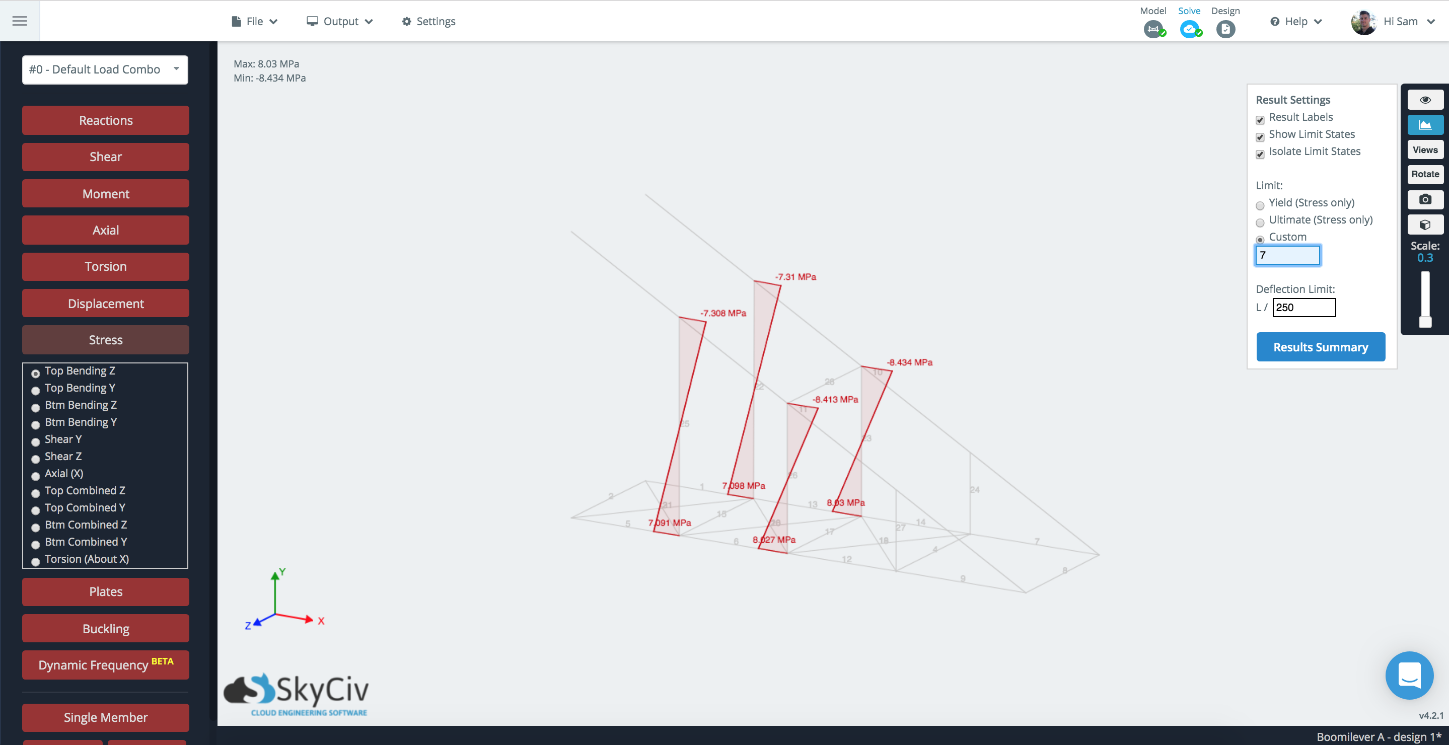
Our goal is to check and ensure compression stress due to bending does not exceed 7 MPa. Use the right Result Visibility option to show any stresses that are above 7 MPa:
This type of failure can be seen in the following video:
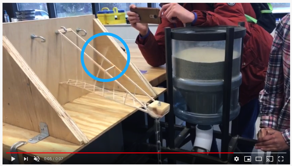
The video shows the struts that connect the tension and compression chords are going to fail with a combination of bending and buckling. This coincides with our model above that shows the key failure points are at these connections.
How to strengthen against Bending Failure
Here we can see there are four members that are prone to bending failure – as their negative values exceed our compression limit of 7 MPa. Now that I have identified these weaker members, I can strengthen them by increasing the section height:
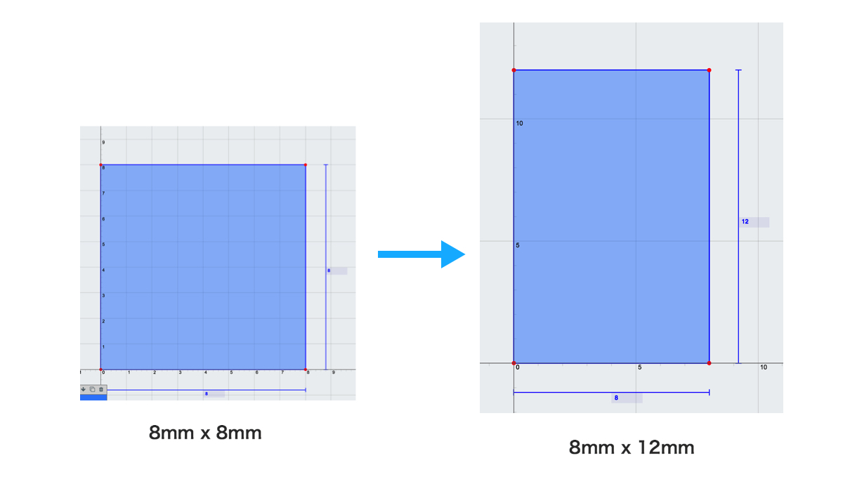
The increase in height of the member will increase its Moment of Inertia, a section property that directly relates to the cross sections strength. In this case, the as the height of the member increases, bending stress decreases, and vice versa. Imagine trying to bend the same piece of wood, but with these two shapes, which would be harder to break?
By making this change I was able to reduce the amount of stress caused by bending forces to a maximum of about 6.7 MPa.
Another option, is to add a cross member to help distribute the force across another member. This may add weight to your structure so might not always be preferable over Option 1 (you’ll have to consider the difference in adding one member as opposed to increasing the section size and weight of multiple members. In this case, we added a bracing member to strengthen the structure:
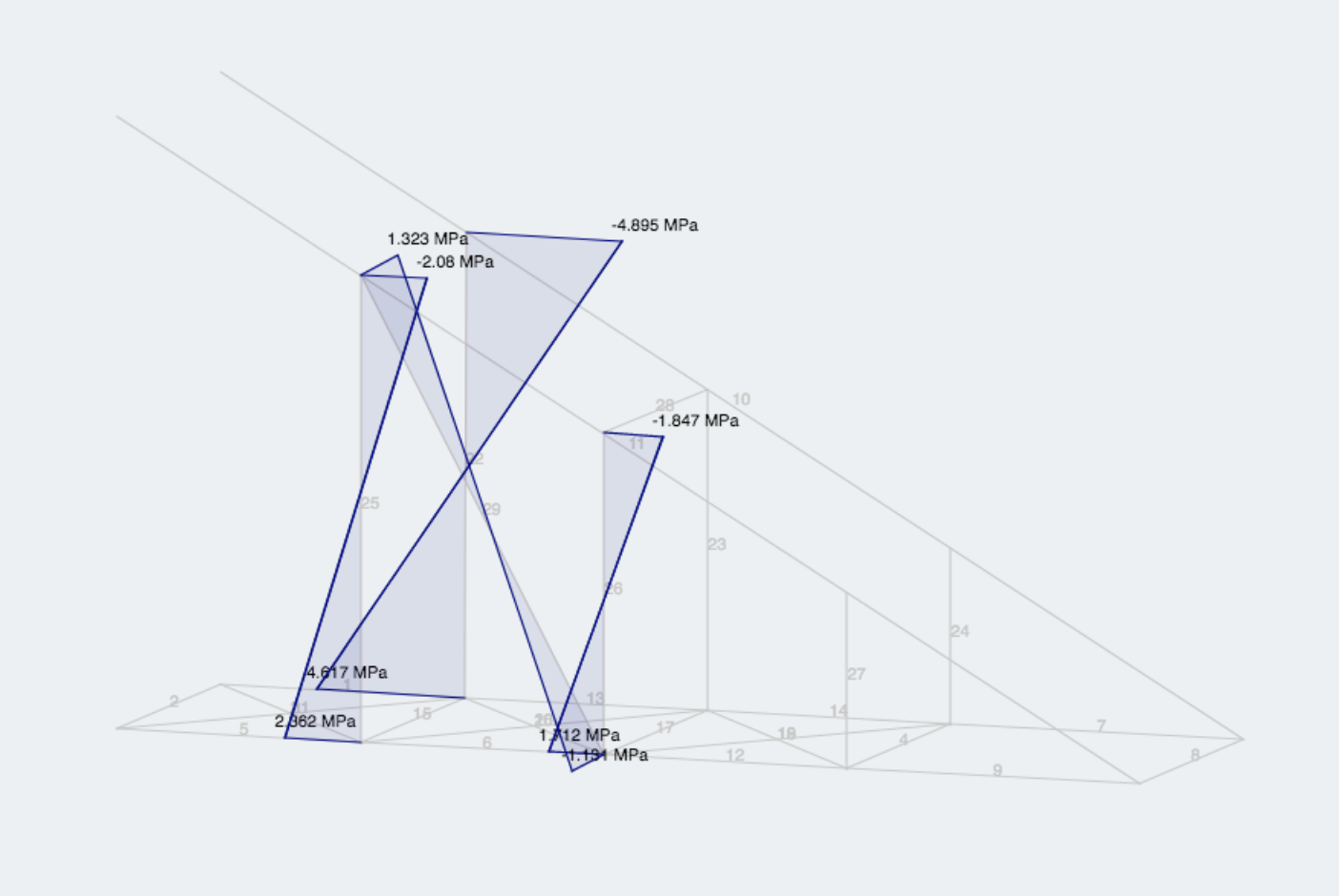
Evidently, adding that one bracing member helped to distribute the forces more evenly along the three members. It even alleviated the excessive stresses of the members on the other side (reduced from -7.31 to -4.895 MPa). Note however, as shown this will disrupt any symmetry in your structure.
The pattern on these bracing members (or truss members) depends on your design. Here are some types of trusses and their strengths and weaknesses.
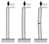
2. Buckling Failure
This is a very common failure for slender, thin members. Buckling is the failure mode of a structural member experiencing high compressive stresses that cause a sudden sideways deflection. Imagine pushing down on a member like so, then it kicks out and collapses like so:
In the case of our boomilever, the relative ratio of the cross section dimensions to the length of the members makes our members more prone to buckling. We can test for Buckling by running a buckling analysis in the software under Solve. This will check your model to see if any members are at risk of buckling:
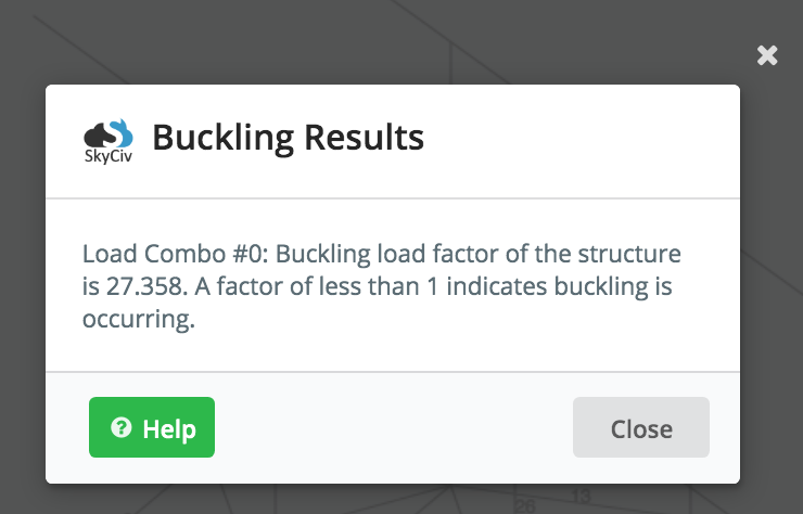
As the alert suggests, a number less than 1 indicates buckling. So our Boomiliever is OK at the moment for buckling. If there were any buckling issues, they would show up as red members on the structure so that you can identify the critical members and modify your design.
Note: Buckling is especially important in Science Olympiad’s Towers competition as there are a lot of column members.
3. Connections/Supports
The base and significant connections (like your distal end) should also be designed ahead of time. This part of the design can make or break your structure’s success… literally! Let’s look at the support base first. This connects two members in tension to the the main board. Your structure should not be failing at the base. If you need some help with this, refer to Aia’s guide on designing a boomilever, it has a great guide on an effective base design that weighs ~1.5g and will support 18-19 kg.
TL; DR
We recommend checking the following to identify any failure areas of your Boomilever:
- Identify any stresses exceeding 7 MPa. Toggle through the Stress results with a stress limit of 7 MPa to identify these. If members are failing, you can try:
- Increase the area of the cross section
- Add bracing members
- Change structure formation or truss style
- Run a buckling analysis (especially for column or vertical members) and look for a value of greater than 1
- Shorten the length of the member
- Increase the area of the cross section
- Add bracing members along the way
- Make sure you have a strong base, it should not be the cause of failure
- If it is, check out Aia’s guide for a strong base design.