The upcoming analysis will encompass both geometric and material nonlinearity. It also offers real-time tracking of the load-displacement curve, enabling an in-depth investigation of the member’s capacity while optimizing computational time. The results will provide insights into the member’s capacity, its deformed state, and its failure status.
Step 1. Model Parts
Go to the ‘Main Parts’ menu and select the ‘PROFILE’ tab. To input the sections’ geometry, import a DXF file stored locally on your PC. The DXF file can be received from here
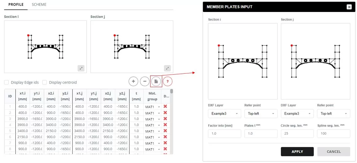
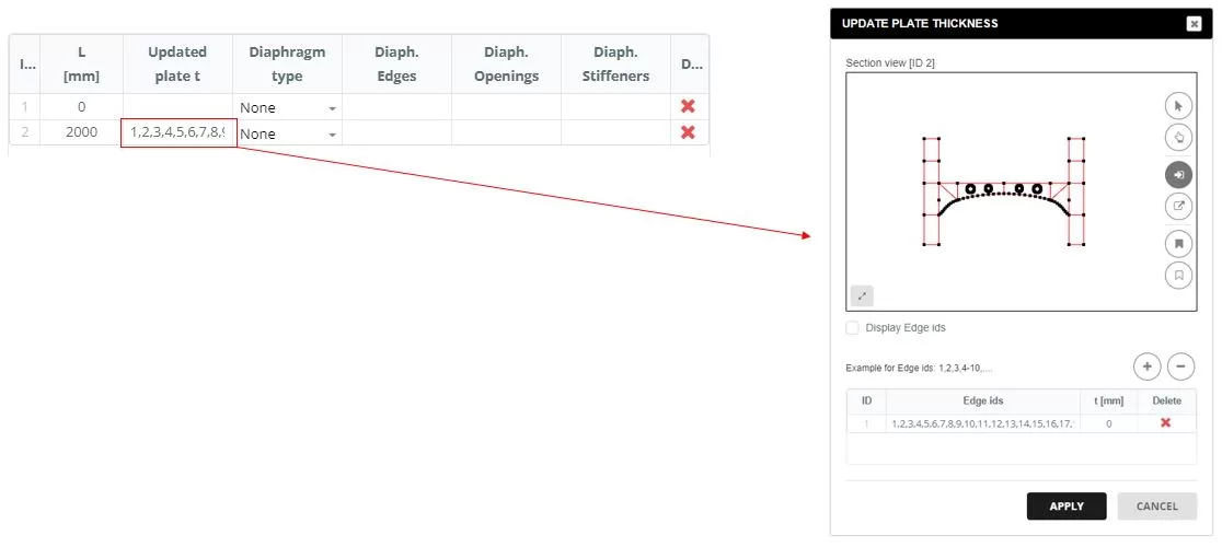
Navigate to the ‘SCHEME’ tab. When you click on the ‘Updated plate t’ column cell, a popup window will appear. In this window, update the thickness for all edges to t=0 mm.
Add diaphragms to the sections, selecting the ‘Polygon’ type. The edges for the diaphragm are defined in a popup window that appears when you click on the ‘Diaphragm Edges’ column cell. In the ‘DIAPHRAGM INPUT’, select the edges that form the diaphragm shape and input the thickness (t).
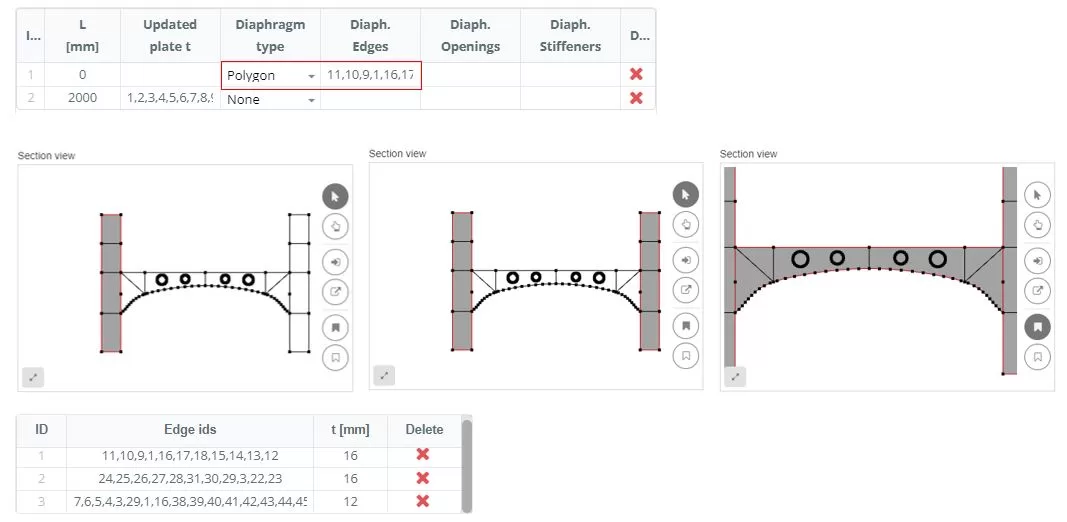
Add diaphragms to the sections, selecting the ‘Polygon’ type. The edges for the diaphragm are defined in a popup window that appears when you click on the ‘Diaphragm Edges’ column cell. In the ‘DIAPHRAGM INPUT’, select the edges that form the diaphragm shape and input the thickness (t).
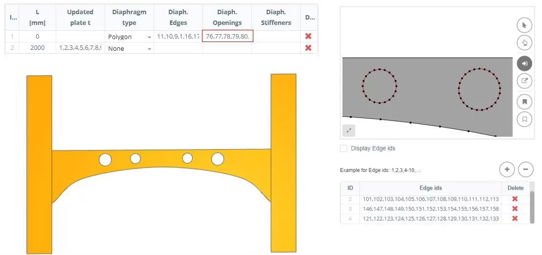
Add diaphragms to the sections, selecting the ‘Polygon’ type. The edges for the diaphragm are defined in a popup window that appears when you click on the ‘Diaphragm Edges’ column cell. In the ‘DIAPHRAGM INPUT’, select the edges that form the diaphragm shape and input the thickness (t).
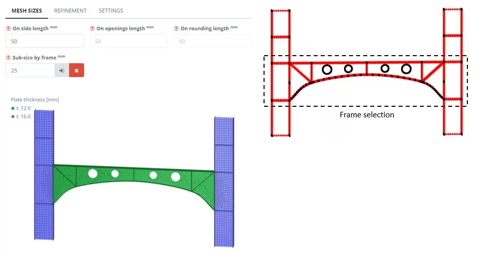
Step 2. Meshing
Navigate to the ‘Meshing’ menu. Set the FE element size to 50 mm, by frame set sub-mesh to the beam edges and then click the ‘Generate’ button.
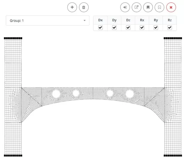
Step 3. Boundaries and Load
Go to the ‘Boundaries’ > ‘Nodes (Custom)‘ menu. Add a new boundary group named ‘Group: 1’. Select the nodes and apply fixed constrains
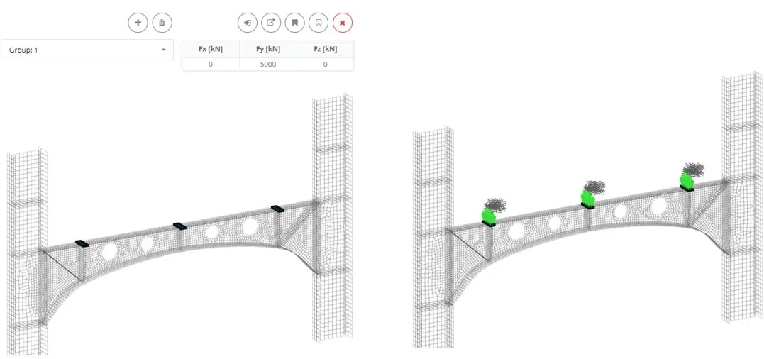
Go to the ‘Loads > ‘Force Area (Custom)‘ menu. Add a new Load group named ‘Group: 1’. Select the elements above vertical stiffeners, and then assign a load Fy of 5000 kN
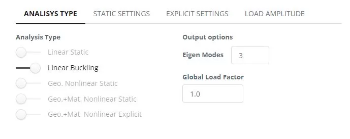
Step 4. Linear Buckling Analysis
Navigate to the ‘Analysis‘ menu. Select Linear Buckling. Click ‘Perform Analysis’ button.
Step 5. Imperfection from buckling mode
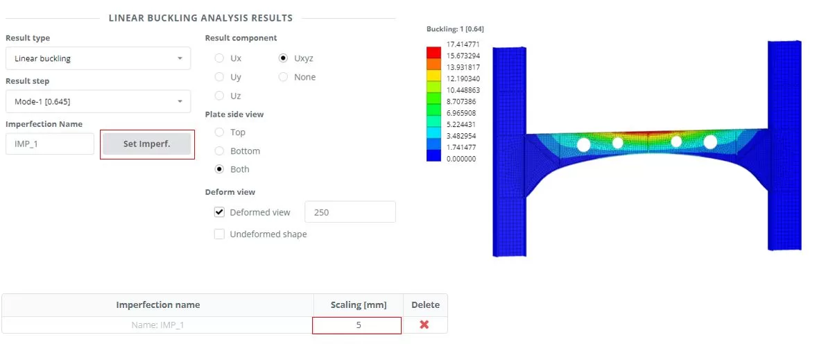
Navigate to the ‘Results’ menu, choose your preferred results options, and click ‘Display’ to view the deformed state of the model. Click ‘Set Imperf.’. Navigate to the ‘Imperfections‘ > ‘From buckling’ menu, set scaling to 5 mm.
Step 6. Nonlinear Analysis
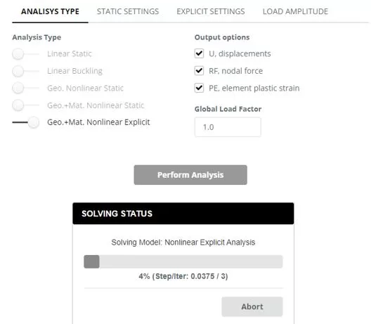
Navigate to the ‘Analysis‘ menu. Select Nonlinear Explicit including geometry and material nonlinearity. Click ‘Perform Analysis’ button.
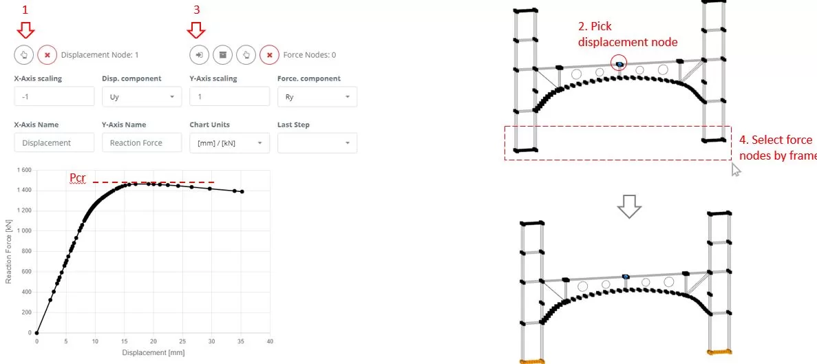
While the analysis is in progress, navigate to ‘Chart’ menu. First, select a node to measure the Uy displacement (steps 1 and 2). Then, using frame selection, choose nodes from which to extract the Ry reaction forces (steps 3 and 4). Monitor the chart’s changes to identify the critical force (Pcr) that leads the structure to failure. Terminate the ongoing analysis once the failure state is detected.
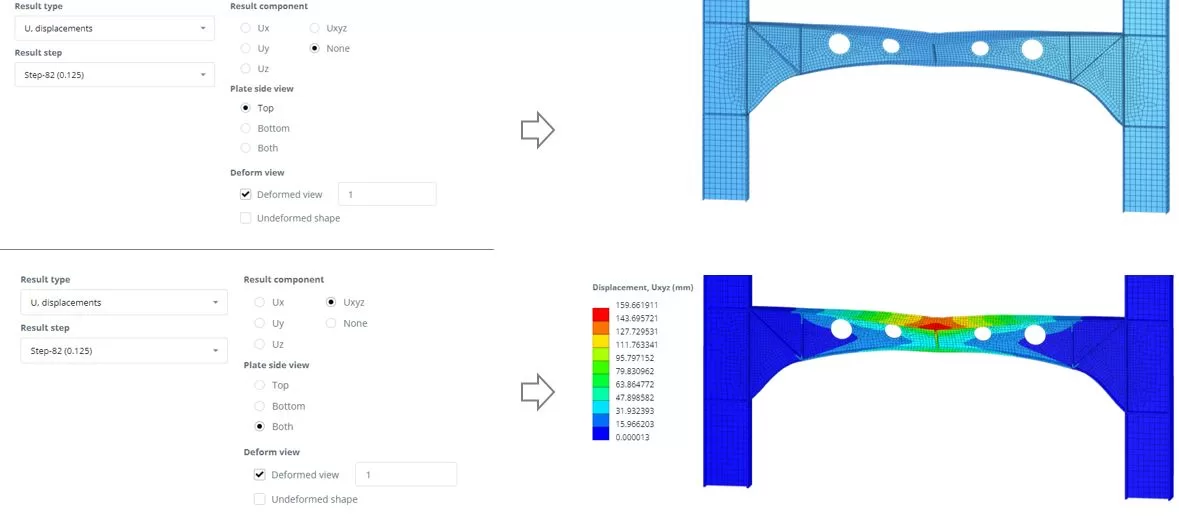
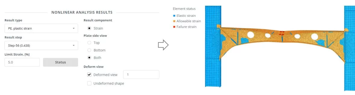
Step 7. Results
Navigate to the ‘Results’ menu, choose your preferred results options, and click ‘Display’ to view the deformed state of the model.