In this article, we will develop a Slab Design Example using the last version of ACI-318-19: “Building Code Requirements for Structural Concrete,” consisting of the modeling in SkyCiv of a Reinforced Concrete Low-Rise Building focusing on the comparison of software results and hand calculations by an accepted method by ACI: “The Direct Design Method for Slabs.” This procedure consists in assigning into different strips along the main directions and frames of the building the total moment by convenient factors to determine the quantity of reinforcement and the location in the slab.
We hope you have read the previous article, Plate Design in S3D, to introduce yourself to modeling and designing plates using SkyCiv. Another helpful piece of information we suggest you consider is found in How to model plates? Once you complete reading both docs, feel free to dive into the following full-worked slab comparison example!
General Building Layout
The following images show an isometric view and plan dimensions of the example to be calculated. The building has two elevated flat slabs without beams between column supports.
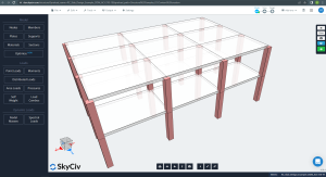
Figure 1. Isometric view of the building example
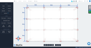
Figure 2. Slab plan dimensions
Direct Design Method for Two-Way Slabs (DDM)
Limitations
ACI 318 permits using the DDM to design reinforced concrete slabs for gravity loads, which gather some requisites according to geometry, load relations, symmetry, etc. We can summarize these limitations in the following list (PCA Notes):
- “There must be three or more continuous spans in each direction.”: Figure 2 shows three spans in each main direction, longitudinal and transversal. Ok!
- “Slab panels must be rectangular with a ratio of longer to shorter span (centerline-to-centerline of supports) not greater than 2.”: According to figure 2, the ratio is equal to \({\frac{l_1}{4}=\frac{6m}{4m}=1.5 < 2}\). Ok!
- “Successive span lengths (centerline-to-centerline of supports) in each direction must not differ by more than 1/3 of the longer span”. Span lengths are the same in each direction, 6m to longitudinal and 4m to transversal. Ok!
- “Columns must not be offset more than 10% of the span (in the direction of offset) from either axis between centerlines of successive columns”. The building example doesn’t have offsets in columns. Ok!
- “Loads must be uniformly distributed, with the unfactored or service live load not more than two times the unfactored or service dead load (L/D ≤ 2)”. Taking the values of each gravity load, the ratio is defined as \({\frac{L}{D}=\frac{2}{7.8}=0.256 < 2}\). Ok!.
- “For two-way beam-supported slabs, relative stiffness of beams in two perpendicular directions must satisfy the minimum and maximum requirements given in the code.” Already satisfied; there are no beams in the slabs. Ok!
- “Redistribution of negative moments by code is not permitted.” Due to the simplicity of the example, it won’t be necessary to redistribute negative moments in the slabs. Ok!.
Longitudinal and transverse strips definition
The slab in DDM has to be divided into two main strips for the analysis and design of a particular line grid: column and middle strips. The width for column strips is the lesser of \({\frac {l_1}{4}}\) and \({\frac{l_2}{4}}\), where \({l_1}\) is the length of the span along the line grid and \({l_2}\) is the transverse length perpendicular.
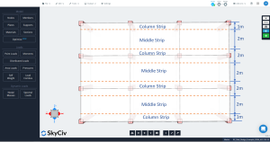
Figure 3. Longitudinal column and middle strips.
![]()
Figure 4. Transverse column and middle strips.
Minimum thickness
ACI-318 suggests using the equation: \({t_{min}}= {\frac{l_n}{30}}={\frac{6m-0.50m}{30}}=0.1833m = 0.20m\)
Preliminary shear strength check
Before calculating the steel rebar reinforcement, it is recommended to check the shear capacity of the slab, one for direct shear in the connection and the other for the punching shear capacity on the connection slab column.
To calculate the shear demand, we use the following gravity loads:
- Self-weight slab: \({SW={\gamma_c}\times {t_{slab}}={24 {\frac{kN}{m^3}}}\times {0.20m}=4.8{\frac{kN}{m^2}} }\)
- Superimposed dead load: \({SD={3 {\frac{kN}{m^2}}}}\)
- Total dead load (SW+SD): \({D={7.8 {\frac{kN}{m^2}}}}\)
- Live load (Residential occupancy) : \({L={2 {\frac{kN}{m^2}}}}\)
- Factored strength load (1.2D+1.6L): \({q_{u}={12.56 {\frac{kN}{m^2}}}}\)
The first shear check is the “beam-shear” type, where the following image indicates the area to be considered to obtain the total shear. We inspect each direction, taking the more extensive area.
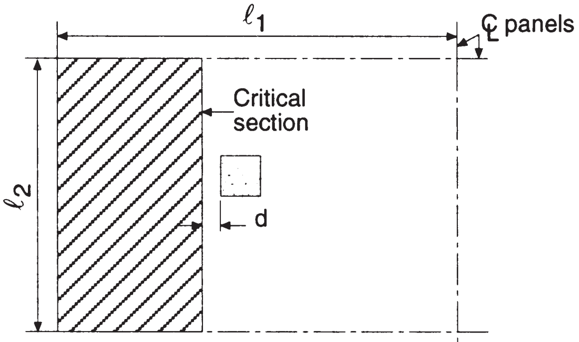
Figure 5. Beam shear at interior column (Nadim Hassoun and Akthem AI-Manaseer, “Structural Concrete Theory and Design”)
Where:
- Length span in longitudinal direction, \({l_1 = 6.0m }\)
- Length span in transverse direction, \({l_2 = 4.0m}\)
- Total tributary area, shear in longitudinal direction \({A_t = l_2 \times (\frac{l_1}{2}-\frac{c_1}{2}-d) = 4.0m \times (\frac{6.0m}{2}-\frac{0.50m}{2}-0.17m) = 10.32 m^2}\) (selected)
- Total tributary area, shear in transverse direction, \({A_t = l_1 \times (\frac{l_2}{2}-\frac{c_2}{2}-d) = 6.0m \times (\frac{4.0m}{2}-\frac{0.50m}{2}-0.17m) = 9.48 m^2}\)
- Square columns dimension, \({c_1 = c_2 = 0.50m}\)
- Distance d, \({d = h_{slab} – cover = 0.20m – 0.03m = 0.17m }\)
Therefore, the maximum beam shear in the interior column is
\({V_u =q_u\times A_t =12.56 {\frac{kN}{m^2}}\times 10.32 m^2 = 129.62 kN }\)
This is going to be compared against the shear resistance, \({\phi_sV_c}\)
- Concrete strength, \({f’_c = 25 MPa}\)
- Yield rebar steel strength, \({f_y = 420 MPa}\)
- \({\phi_s = 0.75}\)
- \({\phi_sV_c = 0.17\phi_s \lambda \sqrt(f’_c) b_w d; b_w=l_2}\)
\({\phi_sV_c = 0.17\times 0.75\times 1\times \sqrt(25 MPa) \times 4000 mm\times 170 mm = 433.50 kN }\)
We can see that the shear resistance is greater than the shear demand: \({\phi_sV_c = 433.50 kN > V_u = 129.62 kN }\) Ok!.
According to the following images, we have to calculate the punching shear capacity and the force to be resisted by concrete in the interior slab-column connection. The code’s intention in checking punching shear is to maintain low shear stress values.
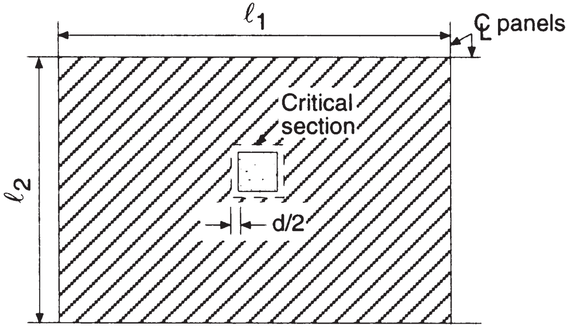
Figure 6. Two-way shear at the interior column (Nadim Hassoun and Akthem AI-Manaseer, “Structural Concrete Theory and Design”)
- Total tributary area, punching shear, \({A_t = l_1 \times l_2 – (c_1+d)^2 = 6.0m \times 4.0m – (0.50m+0.17m)^2 = 23.55 m^2}\) (same area for both main directions)
The total shear force to be resisted is
\({V_u =q_u\times A_t =12.56 {\frac{kN}{m^2}}\times 23.55 m^2 = 295.79 kN }\)
To obtain the punching shear capacity in a two-way slab, we will use the empiric method established by code ACI-318, which considers the maximum shear stress available in the effective perimeter at the critical section. The more conservative expression for the interior column is
- Punching shear capacity, \({\phi_sV_c = 0.33\phi_s \lambda \sqrt(f’_c) b_0 d; b_0=4\times (c_1+d)}\)
Therefore, we have the shear resistance of
\({\phi_sV_c = 0.33\times 0.75 \times 1 \sqrt(25 MPa) \times (4\times (500 mm+170 mm)\times 170mm) = 563.81 kN }\)
We can see that the shear resistance is greater than the shear demand: \({\phi_sV_c = 563.81 kN > V_u = 295.75 kN }\) Ok!.
We have verified the one and the two-way shear demands at the interior column connection. Due to both demands being less than their respective capacities or resistances, we will now move to calculate the main rebar reinforcement for the slab bending.
If you are new at SkyCiv, Sign up and test the software yourself!
Total factored static moment per span.
The maximum moment that can be developed into a double fixed-end beam is an isostatic moment equal to \({M=\frac{w\times {l_1}^2}{8}}\) (See figure 6).
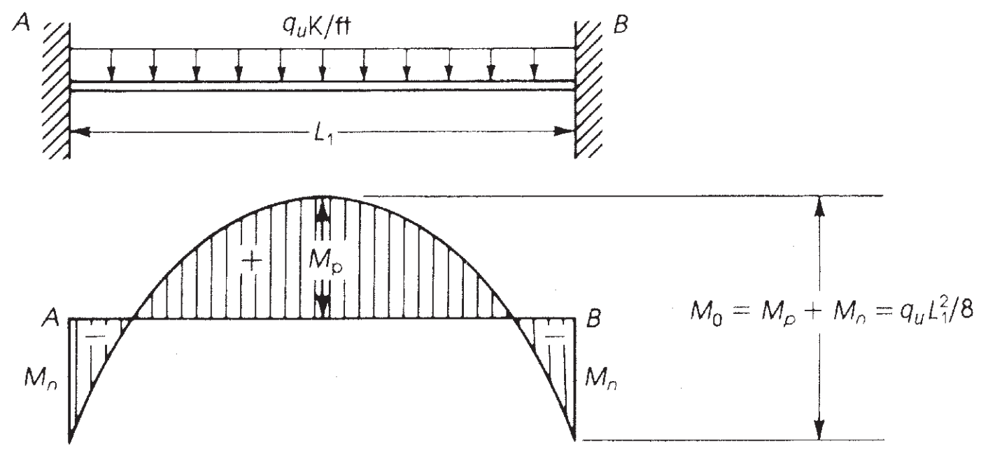
Figure 7. Bending moment in a fixed-end beam. (Nadim Hassoun and Akthem AI-Manaseer, “Structural Concrete Theory and Design”)
ACI-18 takes this principle and, for the Direct Design Method (DDM), establishes the maximum static moment to be considered per span \({M_0}\)
Longitudinal direction:
- \({M_0 = \frac {q_u\times l_2\times {l_{n,1}}^2}{8}}\)
- \({M_0 = \frac {12.56 {\frac{kN}{m^2}}\times 4.0m\times (6m-0.50m)^2}{8}=189.97 kN-m}\)
Transverse direction:
- \({M_0 = \frac {q_u\times l_1\times {l_{n,2}}^2}{8}}\)
- \({M_0 = \frac {12.56 {\frac{kN}{m^2}}\times 6.0m\times (4m-0.50m)^2}{8}=115.40 kN-m}\)
The next step is to assign this total moment considering the panel type, interior or exterior. (See figure 7). After that, due to the spans being continuous, it is necessary to divide also the moment into positive and negative. This last is shown in images 8 and 9.
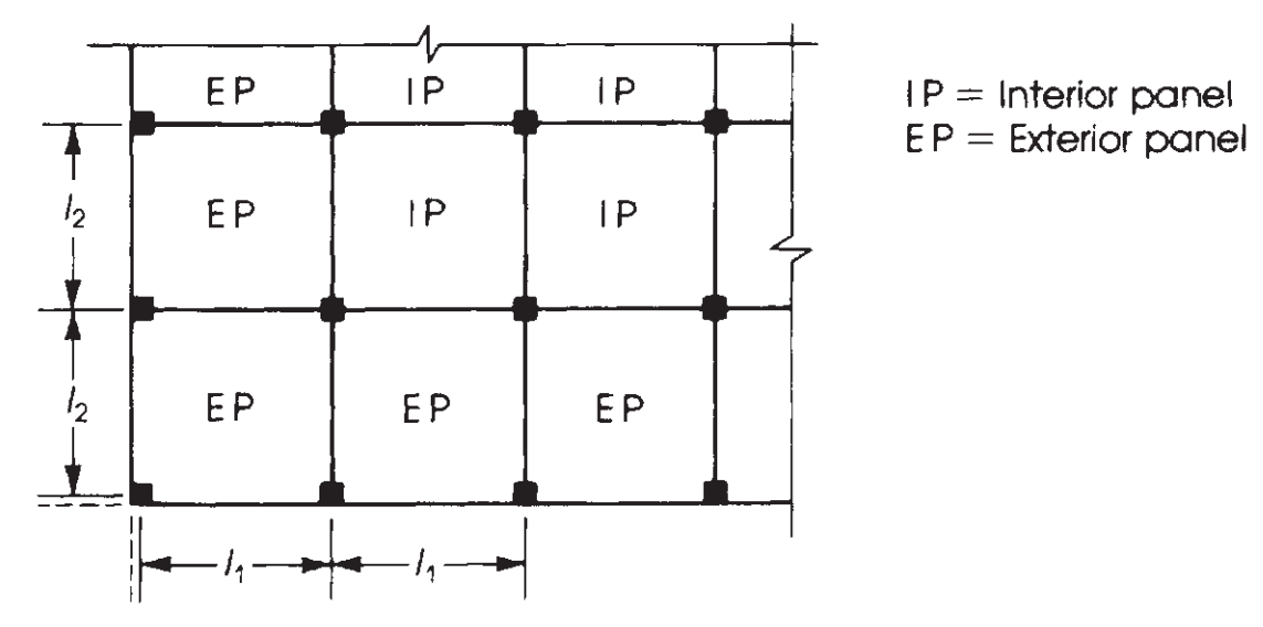
Figure 8. Definition of panels according to their relative position in a slab plan. (Nadim Hassoun and Akthem AI-Manaseer, “Structural Concrete Theory and Design”)
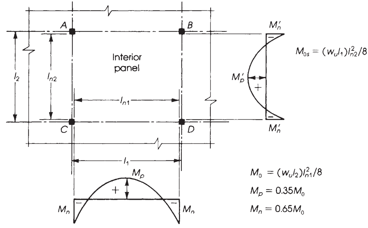
Figure 9. Distribution of moments in an interior panel. (Nadim Hassoun and Akthem AI-Manaseer, “Structural Concrete Theory and Design”)
It is crucial to know the correct distribution of moments depending on the slab we are designing. In this example, we have the last case in the following image (figure 9), “No beams,” applied to a flat slab or solid slab without any beam, neither on the edge nor between supports.
The main difference in the five cases shown in figure 9 is the moment fractions to be assigned on exterior panels, in which the relative restraint at the end changes the values to be calculated.
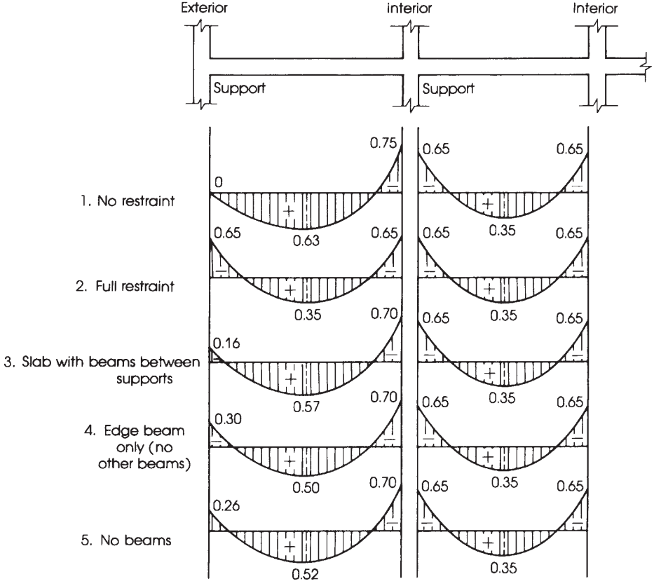
Figure 10. Distribution of total static moment into negative and positive span moments. (Nadim Hassoun and Akthem AI-Manaseer, “Structural Concrete Theory and Design”)
Distribution of the total factored moment \({M_0}\) per span into negative and positive moments.
Once \({M_0}\) has been calculated, it is time to assign the fraction of moments into positive and negative in each design strip, that is, column and middle strips. For more clarity, figure 10 helps specify the appropriate factor to consider in the distribution of the total moment.
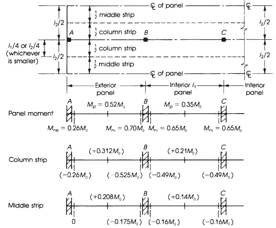
Figure 11. Width of the equivalent rigid frame and distribution of moments in flat slabs. (Nadim Hassoun and Akthem AI-Manaseer, “Structural Concrete Theory and Design”)
Using the previous factors indicated in figure 10, we obtain in the following table the ultimate moment.
Longitudinal direction: \({M_0 = 189.97 kN-m}\)
| Span (ES:Exterior, IS:Interior) | Total moment (kN-m) | Column strip moment (kN-m) | Middle strip moment (kN-m) |
|---|---|---|---|
| Exterior Negative ES | 0.26M0=49.39 | 0.26M0=49.39 | 0 |
| Positive ES | 0.52M0=98.78 | 0.31M0=58.89 | 0.21M0=39.89 |
| Interior Negative ES | 0.70M0=132.98 | 0.53M0=100.68 | 0.17M0=32.29 |
| Positive IS | 0.35M0=66.49 | 0.21M0=39.89 | 0.14M0=26.60 |
| Negative IS | 0.65M0=123.48 | 0.49M0=93.09 | 0.16M0=30.40 |
With the moment once distributed, it is time to determine the steel rebar reinforcement to be placed in the slab. We will only develop one calculation and then all the results into a table.
Moment in the exterior negative span in the column strip, \({M_u = 49.39 kN-m}\)
- Assumed tension-controlled section. \({\phi_f = 0.9}\)
- Column strip width, \({b=2.0m}\)
- Steel reinforcement area, \({A_s = \frac{M_u}{\phi_f\times 0.9d\times fy}= \frac{49.39kN-m}{0.9\times 0.9(0.17m)\times 420 MPa}=853.996 {mm}^2}\)
- \({\rho_{min} = 0.0018}\). Steel minimum reinforcement area, \({A_{s,min}=\rho_{min}\times b\times d = 0.0018 \times 2.0m \times 0.17m =612 {mm}^2}\). Now, check if the section is behaving as tension-controlled.
- \({a = \frac{A_s\times f_y}{0.85\times f’c\times b} = \frac{853.996 {mm}^2\times 420 MPa}{0.85\times 25 MPa\times 2.0m }= 8.439 mm}\)
- \({c = \frac{a}{\beta_1}=\frac{8.439 mm}{0.85} = 9.929mm }\)
- \({\varepsilon_t = (\frac{0.003}{c})\times d – 0.003 = (\frac{0.003}{9.929mm})\times 170mm – 0.003 = 0.048 > 0.005 }\) Ok!, it’s a tension-controlled section!.
| Span(ES:Exterior, IS:Interior) | Column Strip Moment (kN-m) | \({A_{s,calc} ({mm}^2)}\) | \({A_{s,min} ({mm}^2)}\) | \({a (mm)}\) | \({c (mm)}\) | \({\varepsilon_t > 0.005}\) |
|---|---|---|---|---|---|---|
| Exterior Negative ES | 49.39 | 853.996 | 612.0 | 8.439 | 9.929 | 0.048 > 0.005! |
| Positive ES | 58.89 | 1018.259 | 612.0 | 10.063 | 11.839 | 0.040 > 0.005! |
| Interior Negative ES | 100.68 | 1740.844 | 612.0 | 17.204 | 20.24 | 0.022 > 0.005! |
| Positive IS | 39.89 | 689.733 | 612.0 | 6.816 | 8.019 | 0.06 > 0.005! |
| Negative IS | 93.09 | 1609.607 | 612.0 | 15.907 | 18.714 | 0.024 > 0.005! |
Moment in the exterior positive span in the middle strip, \({M_u = 39.89 kN-m}\)
- Assumed tension-controlled section. \({\phi_f = 0.9}\)
- Middle strip width, \({b=2.0m}\)
- Steel reinforcement area, \({A_s = \frac{M_u}{\phi_f\times 0.9d\times fy}= \frac{39.89kN-m}{0.9\times 0.9(0.17m)\times 420 MPa}=689.733 {mm}^2}\)
- \({\rho_{min} = 0.0018}\). Steel minimum reinforcement area, \({A_{s,min}=\rho_{min}\times b\times d = 0.0018 \times 2.0m \times 0.17m =612 {mm}^2}\). Now, check if the section is behaving as tension-controlled.
- \({a = \frac{A_s\times f_y}{0.85\times f’c\times b} = \frac{689.766 {mm}^2\times 420 MPa}{0.85\times 25 MPa\times 2.0m }= 6.816 mm}\)
- \({c = \frac{a}{\beta_1}=\frac{6.816 mm}{0.85} = 8.019 mm }\)
- \({\varepsilon_t = (\frac{0.003}{c})\times d – 0.003 = (\frac{0.003}{8.019mm})\times 170mm – 0.003 = 0.0605 > 0.005 }\) Ok!, it’s a tension-controlled section!.
| Span(ES:Exterior, IS:Interior) | Middle Strip Moment (kN-m) | \({A_{s,calc} ({mm}^2)}\) | \({A_{s,min} ({mm}^2)}\) | \({a (mm)}\) | \({c (mm)}\) | \({\varepsilon_t > 0.005}\) |
|---|---|---|---|---|---|---|
| Exterior Negative ES | 0 | 0.00 | 612.0 | 6.048 | 7.115 | 0.069 > 0.005! |
| Positive ES | 39.89 | 689.733 | 612.0 | 6.816 | 8.019 | 0.061 > 0.005! |
| Interior Negative ES | 32.29 | 558.322 | 612.0 | 6.048 | 7.115 | 0.069 > 0.005! |
| Positive IS | 26.60 | 459.937 | 612.0 | 6.048 | 7.115 | 0.069 > 0.005! |
| Negative IS | 30.40 | 525.642 | 612.0 | 6.048 | 7.115 | 0.069 > 0.005! |
Transverse direction: \({M_0 = 115.40 kN-m}\)
| Span (ES:Exterior, IS:Interior) | Total moment (kN-m) | Column strip moment (kN-m) | Middle strip moment (kN-m) |
|---|---|---|---|
| Exterior Negative ES | 0.26M0=30.00 | 0.26M0=30.00 | 0 |
| Positive ES | 0.52M0=60.00 | 0.31M0=35.77 | 0.21M0=24.23 |
| Interior Negative ES | 0.70M0=80.78 | 0.53M0=61.16 | 0.17M0=19.62 |
| Positive IS | 0.35M0=40.39 | 0.21M0=24.23 | 0.14M0=16.16 |
| Negative IS | 0.65M0=75.01 | 0.49M0=56.55 | 0.16M0=18.46 |
With the moment once distributed, it is time to determine the steel rebar reinforcement to place in the slab. We will only develop one calculation and then all the results into a table.
Moment in the exterior negative span in the column strip, \({M_u = 30.00 kN-m}\)
- Assumed tension-controlled section. \({\phi_f = 0.9}\)
- Column strip width, \({b=2.0m}\)
- Steel reinforcement area, \({A_s = \frac{M_u}{\phi_f\times 0.9d\times fy}= \frac{30.00kN-m}{0.9\times 0.9(0.17m)\times 420 MPa}=518.726 {mm}^2}\)
- \({\rho_{min} = 0.0018}\). Steel minimum reinforcement area, \({A_{s,min}=\rho_{min}\times b\times d = 0.0018 \times 2.0m \times 0.17m =612 {mm}^2}\). Now, check if the section is behaving as tension-controlled.
- \({a = \frac{A_s\times f_y}{0.85\times f’c\times b} = \frac{518.726 {mm}^2\times 420 MPa}{0.85\times 25 MPa\times 2.0m }= 6.048 mm}\)
- \({c = \frac{a}{\beta_1}=\frac{6.048 mm}{0.85} = 7.115mm }\)
- \({\varepsilon_t = (\frac{0.003}{c})\times d – 0.003 = (\frac{0.003}{7.115mm})\times 170mm – 0.003 = 0.069 > 0.005 }\) Ok!, it’s a tension-controlled section!.
| Span(ES:Exterior, IS:Interior) | Column Strip Moment (kN-m) | \({A_{s,calc} ({mm}^2)}\) | \({A_{s,min} ({mm}^2)}\) | \({a (mm)}\) | \({c (mm)}\) | \({\varepsilon_t > 0.005}\) |
|---|---|---|---|---|---|---|
| Exterior Negative ES | 30.00 | 518.726 | 612.0 | 6.048 | 7.115 | 0.069 > 0.005! |
| Positive ES | 35.77 | 618.494 | 612.0 | 6.112 | 7.191 | 0.068 > 0.005! |
| Interior Negative ES | 61.16 | 1057.509 | 612.0 | 10.451 | 12.295 | 0.038 > 0.005! |
| Positive IS | 24.23 | 418.958 | 612.0 | 6.048 | 7.115 | 0.069 > 0.005! |
| Negative IS | 56.55 | 977.799 | 612.0 | 9.663 | 11.368 | 0.042 > 0.005! |
Moment in the exterior positive span in the middle strip, \({M_u = 24.23 kN-m}\)
- Assumed tension-controlled section. \({\phi_f = 0.9}\)
- Column strip width, \({b=4.0m}\)
- Steel reinforcement area, \({A_s = \frac{M_u}{\phi_f\times 0.9d\times fy}= \frac{24.23 kN-m}{0.9\times 0.9(0.17m)\times 420 MPa}=418.958 {mm}^2}\)
- \({\rho_{min} = 0.0018}\). Steel minimum reinforcement area, \({A_{s,min}=\rho_{min}\times b\times d = 0.0018 \times 4.0m \times 0.17m =1224 {mm}^2}\). Now, check if the section is behaving as tension-controlled.
- \({a = \frac{A_s\times f_y}{0.85\times f’c\times b} = \frac{1224 {mm}^2\times 420 MPa}{0.85\times 25 MPa\times 4.0m }= 6.048 mm}\)
- \({c = \frac{a}{\beta_1}=\frac{6.048 mm}{0.85} = 7.115 mm }\)
- \({\varepsilon_t = (\frac{0.003}{c})\times d – 0.003 = (\frac{0.003}{7.115mm})\times 170mm – 0.003 = 0.069 > 0.005 }\) Ok!, it’s a tension-controlled section!.
| Span(ES:Exterior, IS:Interior) | Middle Strip Moment (kN-m) | \({A_{s,calc} ({mm}^2)}\) | \({A_{s,min} ({mm}^2)}\) | \({a (mm)}\) | \({c (mm)}\) | \({\varepsilon_t > 0.005}\) |
|---|---|---|---|---|---|---|
| Exterior Negative ES | 0.00 | 0.00 | 1224.00 | 6.048 | 7.115 | 0.069 > 0.005! |
| Positive ES | 24.23 | 418.958 | 1224.00 | 6.048 | 7.115 | 0.069 > 0.005! |
| Interior Negative ES | 19.62 | 339.247 | 1224.00 | 6.048 | 7.115 | 0.069 > 0.005! |
| Positive IS | 16.16 | 279.420 | 1224.00 | 6.048 | 7.115 | 0.069 > 0.005! |
| Negative IS | 18.46 | 319.189 | 1224.00 | 6.048 | 7.115 | 0.069 > 0.005! |
If you are new at SkyCiv, Sign up and test the software yourself!
SkyCiv S3D Design Module
In this section, we describe the design result using the module for plate design included in SkyCiv. We don’t explain how to model and analyze the structure (for these, see related articles on this topic in our documentation: How to model a structure in SkyCiv?, How to apply loads in my building model? and How to run a linear elastic analysis?)
It is convenient to apply a fine mesh to the slabs to obtain an accurate design result. Please take a look at the following image for more clarity.
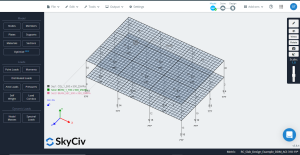
Figure 12. Finer mesh applied to slabs
The next step is to run the design module and select the options which calculate an optimized steel rebar area.
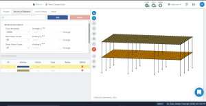
Figure 13. Slab concrete properties definition before design optimization.
Figure 14 represents the plate’s local axes orientation. Because local axis 3 is downward, the “top” is the bottom, and the “bottom” will be the top, thus correctly taking the data from the design.
Another important fact is the slab mesh size; it is a plate square element with plan dimensions of 500mm x 500mm. SkyCiv S3D gives the reinforcement area as an integrated value per finite element. Thus, if we want to obtain the total rebar area of a column or middle strip, we need to calculate the mean value from the number of elements that sum the strip width being analyzed. For example, for the column strip, four elements will be considered (4×0.5m = 2m).
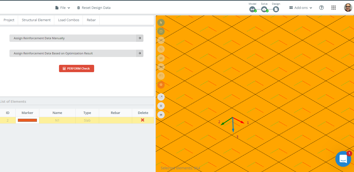
Figure 14. Local axes orientation in slab example.
First, we analyze the reinforcement area required along the longitudinal direction in axis 1.
Column Strip
- Exterior negative moment (top reinforcement): \({A_{s,top} =(119.09\times 2 + 952.72 + 833.64 )\frac{{mm}^2}{m} \times 0.50m = 1012.27 {mm}^2}\)
- Exterior positive moment (bottom reinforcement): \({A_{s,bot} = 4*463.90 \frac{{mm}^2}{m}\times 0.50m = 927.80 {mm}^2}\)
- Exterior interior negative moment (top reinforcement): \({A_{s,top} =(1071.82\times 2 +714.54 \times 2 )\frac{{mm}^2}{m} \times 0.50m = 1786.36 {mm}^2}\)
- Interior positive moment(bottom reinforcement): \({A_{s,bot} = 4*309.27 \frac{{mm}^2}{m}\times 0.50m = 618.54 {mm}^2}\)
- Interior negative moment (top reinforcement): \({A_{s,top} =(714.54\times 2 +952.73 \times 2 )\frac{{mm}^2}{m} \times 0.50m = 1667.27 {mm}^2}\)
Middle Strip
- Exterior negative moment (top reinforcement): \({A_{s,top} =(119.09\times 4)\frac{{mm}^2}{m} \times 0.50m = 238.18 {mm}^2}\)
- Exterior positive moment (bottom reinforcement): \({A_{s,bot} = (463.90\times 2 +412.36 \times 2 ) \frac{{mm}^2}{m}\times 0.50m = 876.26 {mm}^2}\)
- Exterior interior negative moment (top reinforcement): \({A_{s,top} =(357.27\times 2 +476.36 \times 2 )\frac{{mm}^2}{m} \times 0.50m = 833.63 {mm}^2}\)
- Interior positive moment(bottom reinforcement): \({A_{s,bot} = 4*257.72 \frac{{mm}^2}{m}\times 0.50m = 515.44 {mm}^2}\)
- Interior negative moment (top reinforcement): \({A_{s,top} =(357.27\times 2 +476.36 \times 2 )\frac{{mm}^2}{m} \times 0.50m = 833.63 {mm}^2}\)

Figure 15. Optimization results in direction “1” and the top side (Bottom side, actually).

Figure 16. Optimization results in direction “1” and the bottom side (Top side, actually).
Finally, we analyze the reinforcement area required along the transverse direction in axis 2.
Column Strip
- Exterior negative moment (top reinforcement): \({A_{s,top} =(91.55\times 2 + 457.73 + 549.28 )\frac{{mm}^2}{m} \times 0.50m = 595.055 {mm}^2}\)
- Exterior positive moment (bottom reinforcement): \({A_{s,bot} = (269.68\times 3+239.72) \frac{{mm}^2}{m}\times 0.50m = 524.38 {mm}^2}\)
- Exterior interior negative moment (top reinforcement): \({A_{s,top} =(823.92\times 2 +549.28 +457.73)\frac{{mm}^2}{m} \times 0.50m = 1327.43 {mm}^2}\)
- Interior positive moment(bottom reinforcement): \({A_{s,bot} = (179.79\times 3+149.82) \frac{{mm}^2}{m}\times 0.50m = 344.60 {mm}^2}\)
- Interior negative moment (top reinforcement): \({A_{s,top} =(823.92\times 2 +549.28 +457.73)\frac{{mm}^2}{m} \times 0.50m = 1327.43 {mm}^2}\)
Middle Strip
- Exterior negative moment (top reinforcement): \({A_{s,top} =(183.09\times 2+91.55\times 6)\frac{{mm}^2}{m} \times 0.50m = 457.74 {mm}^2}\)
- Exterior positive moment (bottom reinforcement): \({A_{s,bot} = (209.75\times 2 +179.79 \times 2 +149.82 \times 4) \frac{{mm}^2}{m}\times 0.50m = 689.18{mm}^2}\)
- Exterior interior negative moment (top reinforcement): \({A_{s,top} =(274.64\times 2+91.55\times 6)\frac{{mm}^2}{m} \times 0.50m = 549.29 {mm}^2}\)
- Interior positive moment(bottom reinforcement): \({A_{s,bot} = (119.86\times 4 + 89.89\times 4) \frac{{mm}^2}{m}\times 0.50m = 419.50 {mm}^2}\)
- Interior negative moment (top reinforcement): \({A_{s,top} =(274.64\times 2+91.55\times 6 )\frac{{mm}^2}{m} \times 0.50m = 549.29 {mm}^2}\)

Figure 17. Optimization results in direction “2” and the top side (Bottom side, actually).
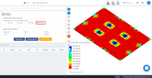
Figure 18. Optimization results in direction “2” and the bottom side (Top side, actually).
Results comparison
The following table shows the results for the DDM (“Direct Design Method”) and the S3D steel rebar optimization.
| Span (ES:Exterior, IS:Interior) | Column Strip (S3D Design) \({A_s ({mm}^2)}\) | Column Strip (ACI-318 DDM) \({A_s ({mm}^2)}\) | % Dif | Middle Strip (S3D Design) \({A_s ({mm}^2)}\) | Middle Strip (ACI-318 DDM) \({A_s ({mm}^2)}\) | % Dif |
|---|---|---|---|---|---|---|
| Exterior Negative ES | 1012.27 | 853.996 | 15.636 | 238.18 | 0 (612.0) | 100.00 |
| Positive ES | 927.80 | 1018.259 | 9.75 | 876.26 | 689.733 | 21.287 |
| Interior Negative ES | 1786.36 | 1740.844 | 2.48 | 833.63 | 558.322 (612.0) | 26.586 |
| Positive IS | 618.54 | 689.733 | 11.51 | 515.44 | 459.937 (612.0) | 18.734 |
| Negative IS | 1667.27 | 1609.607 | 3.459 | 833.63 | 525.642 (612.0) | 26.586 |
Transverse direction
| Span (ES:Exterior, IS:Interior) | Column Strip (S3D Design) \({A_s ({mm}^2)}\) | Column Strip (ACI-318 DDM) \({A_s ({mm}^2)}\) | % Dif | Middle Strip (S3D Design) \({A_s ({mm}^2)}\) | Middle Strip (ACI-318 DDM) \({A_s ({mm}^2)}\) | % Dif |
|---|---|---|---|---|---|---|
| Exterior Negative ES | 595.055 | 518.726 | 12.827 | 457.74 | 0 (1224) | 100.00 |
| Positive ES | 524.38 | 618.494 | 17.948 | 689.18 | 418.958 | 39.209 |
| Interior Negative ES | 1327.43 | 1057.509 | 20.334 | 549.29 | 339.247 | 38.239 |
| Positive IS | 344.60 | 418.958 | 21.578 | 419.50 | 279.42 | 33.392 |
| Negative IS | 1327.43 | 977.799 | 26.339 | 549.29 | 319.189 | 41.891 |
Conclusion
We have demonstrated in this article that SkyCiv module for plate design calculates the steel reinforcement for bending slab accordingly to the code ACI-318-19. Comparing the results from the analysis in the column strips, where because of their relative stiffness, the moments are highly concentrated, the differences between hand calculations and optimization by S3D round a value of 10 – 15%. This practicality indicates an excellent match between analysis and design procedures.
For middle strips, the results differ a bit more because the code only assigns the rest of the moment after taking the corresponding column strips. This will impact the match when we compare it with the analysis from the software, which is more accurate.
New to SkyCiv? Sign up and try the software yourself!