Analysis type
Linear Static – static analysis, takes into account elastic material properties
Linear Buckling – linear stability analysis for selected number of eigenmodes.
Geometry Nonlinear Static – iterative analysis, takes into account elastic material properties and geometry nonlinearity (large displacements)
Geometry + Material Nonlinear Static – iterative static analysis takes into account material and geometry nonlinearity (large displacements)
Geometry + Material Nonlinear Dynamic– iterative dynamic analysis takes into account material and geometry nonlinearity (large displacements)
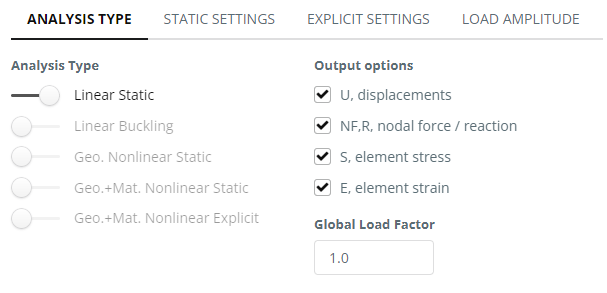
Static settings
Global Load Factor – the factor will be multiplied by all the load values in the model for analysis
Time period and time increment – iteration analysis settings. These settings for the most analysis cases are set up properly and can be used by default.
Dynamic settings
Time period and time increment – iteration analysis settings.
Results output steps – for results recording during the analysis
Damping – Rayleigh damping, alternatively termed proportional damping, represents a variant of viscous damping allocated throughout the elements. This approach constructs a damping matrix, denoted as , through a linear amalgamation of the mass matrix and the stiffness matrix
Load Amplitude
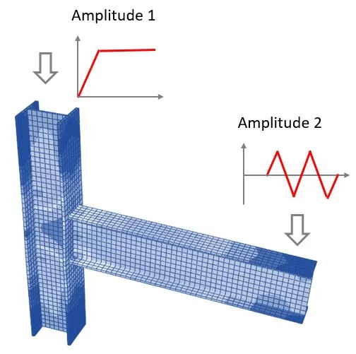
In nonlinear finite element analysis, the load-time function is a critical feature that defines how loads are applied over time. The software provides the capability to assign varying load intensities at different instances, which is especially useful in simulating real-world conditions where loads are not constant.
To enhance this functionality, the software allows the definition of two amplitude options for the loads. These amplitude options enable users to specify a pattern or a sequence of load values that change over the course of the analysis.
The first amplitude option can define the initial ramp-up of the load, allowing for a gradual increase from zero to the maximum load value, reflecting a more realistic application of force or pressure on the structure. The second amplitude option can describe a subsequent phase, such as a holding pattern, cyclic loading, or a decrease to simulate the removal of the load.
If you only need to deal with a single load amplitude, where all applied loads follow the same function, use ‘Amplitude 1’ as an example. The program will ignore the second amplitude if it is not used.