Designing roof trusses using SkyCiv
In this tutorial, we will design a roof truss for a garage with the following information:
- Location: 8050 SW Beaverton Hillsdale Hwy, Portland, OR 97225, USA
- Building length: 10.0m
- Building width: 7.0m
- Eave height: 4.0m
- Roof truss height: 2.0m
- Roof angle: 29.745°
- Enclosure: Open building
We will be using an L shape (AISC) section for the roof truss, isolating the critical truss (spaced at 3.33m) and analyzing it as a simply-supported truss assembly.
Visit our other tutorials for more information about the definition of truss and types of trusses. Or try out our Truss Solver to test and calculate the axial forces for truss, roof and rafters.
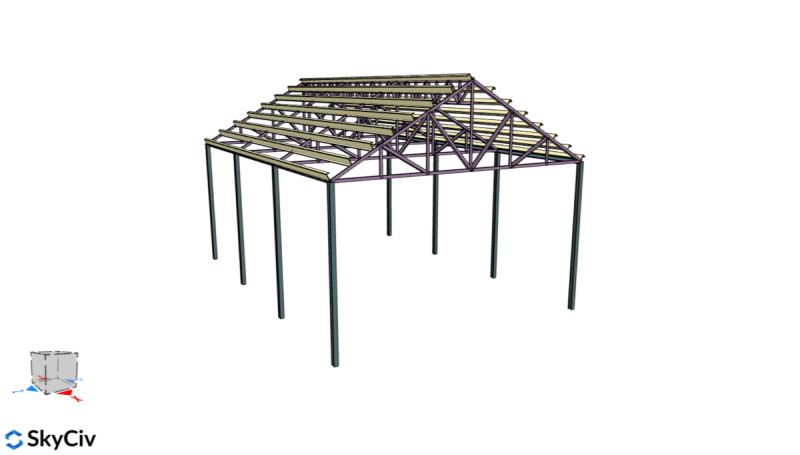
Figure 1. 3D Render of the structure.
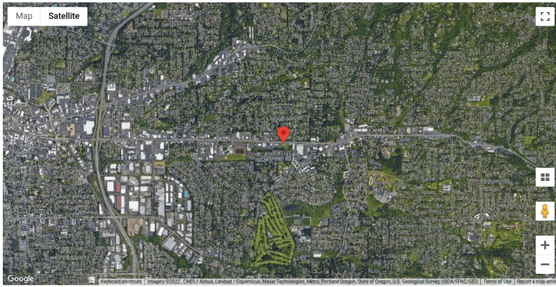
Figure 2. Site location.
Roof Loads
In designing the components, we will assess the roof loads acting on the roof trusses. Note that the wind load to be used here will be for Components and Cladding for designing the roof truss members.
In the design of the roof truss members, ASCE 7-16 LRFD Load Combinations will be used. Using the Truss Builder, we can calculate axial forces and reactions for the truss members.
Dead Load
We will assume the following loads to be carried by the roof trusses:
- Roof sheets and accessories: 0.15 kPa (applied at top chord)
- Ceiling: 0.25 kPa (applied at bottom chord)
The self-weight will be checked when we already have the initial section and will iterate the design from this data. For roof trusses, using spacing equal to 3.33m from center to center (critical member), the superimposed dead load is:
\({W}_{sdead,top} = 0.15kPa(3.33m) = 0.5 kN/m \)
\({W}_{sdead,bottom} = 0.25kPa(3.33m) = 0.833 kN/m \)
Live Load
From Table 4.3-1 of ASCE 7-16, the live load for roofs (ordinary flat, pitched, and curved roofs) is equal to 0.96 kPa. Therefore, for roof trusses:
\({W}_{live} = 0.96kPa(3.33m) = 3.197 kN/m \)
Note that the live load acting on the roof truss, it is assumed to be acting on the horizontal projection of the area. Since we will be applying this on the top chord, we will just multiply this load to the member length, and apply it to the top chord nodes.
Wind Load
For the wind load, we will be using wind pressure calculation for components and cladding (Chapter 30 of ASCE 7-16). We will be using the SkyCiv Load Generator to calculate the wind loads acting on the roof trusses.
The following information is used for the calculation of wind pressures:
| Location | 8050 SW Beaverton Hillsdale Hwy, Portland, OR 97225, USA |
| Risk Category | I (Garage) |
| Building Length | 10.0 m |
| Building Width | 7.0 m |
| Mean Roof Height | 5.0 m |
| Roof angle | 29.745° |
Based on the satellite image from Google Maps, we can see that all directions are categorized as Exposure Category B.
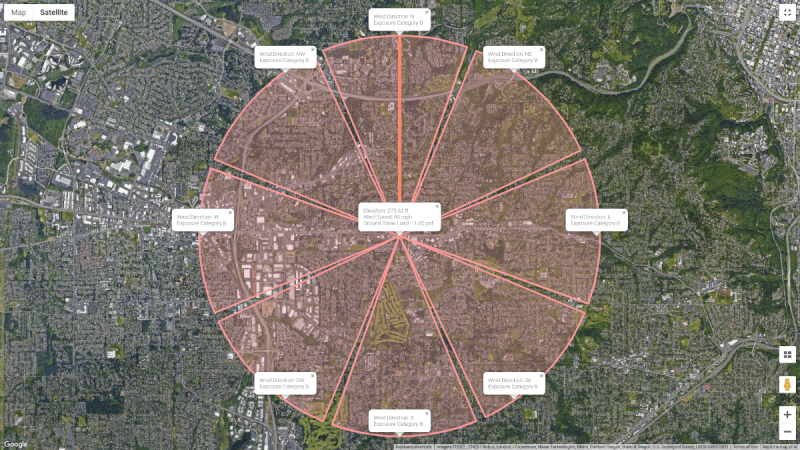
Figure 3. Location of the structure and the Exposure Category for each upwind direction.
In addition, some directions have hills but the effect of the topography is negligible as the location of the structure is on the lower half of the height between the upwind foot and the peak elevation. Therefore, Kzt is equal to 1.0 for all directions.
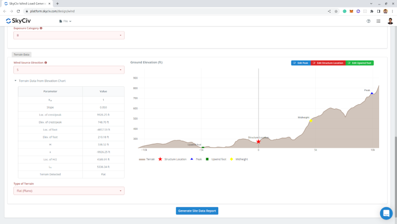
Figure 4. Elevation chart from Google Maps and the corresponding topographic factor for wind coming from the south direction.
On the Structure Data tab, we will select Open-Pitched/Duopicth as the roof profile as the garage is not enclosed by walls. Take note that the Building Length, L, here is the distance perpendicular to the pitch of the roof, and the Mean Roof Height, h, is the average of eave height and roof apex height.
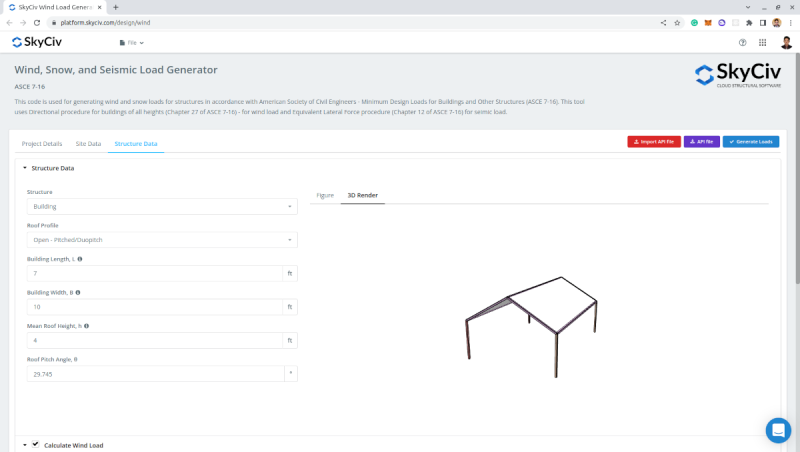
Figure 5. Structure data.
On the “Calculate Wind Load” parameters, we need to set the Type of Structure to ASCE 7-16 – Buildings – Components and Cladding since we will be designing the roof truss as components. The Enclosure Classification is set to Open Buildings and the Wind Blockage is set to “Clear or Empty Under” as, during typhoons, the cars below would not block more than 50% of the wind area below. For the Area of Roof Cladding, we will calculate the effective wind area for the roof trusses.
The effective wind area for the roof truss – length is equal to 3.33m:
\({A}_{truss} \) = spacing x length = 3.33m(7.0m) =\( 23.31 {m}^{2} \)
However, in Section 26.2 of ASCE 7-16, by definition of the effective wind area, the effective width need not be less than one-third of the span length. Therefore:
\({A}_{truss} \) = spacing x length ≥ (length/3) x length = 3.33m (7m) ≥ (7m/3) (7m) = \( 23.31 {m}^{2} \)
The input for the wind load is as follows:
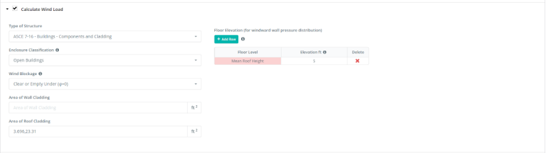
Figure 6. Wind parameters for open building – components and cladding.
From these parameters, the design wind pressures can be calculated:
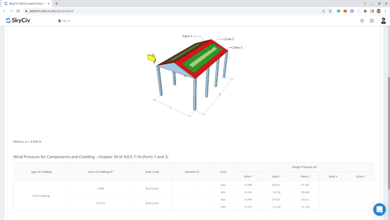
Figure 7. Wind pressures for each zone.
Since the wind pressures for zones 1, 2, and 3 are all the same, the zoning will not matter. Therefore, for roof load on the truss, we will have two cases – the positive (or max) case and negative (or min) case:
\({W}_{wind+} = 0.651kPa (3.33m) = 2.168 kN/m \)
\({W}_{wind-} = -0.453kPa (3.33m) = -1.508 kN/m \)
Note that the positive value here means that the pressure is acting towards and perpendicular to the roof surface and the negative value means that the pressure is acting away and perpendicular to the roof surface.
Snow Load
Using the same site data used in Wind Load:
| Location | 8050 SW Beaverton Hillsdale Hwy, Portland, OR 97225, USA |
| Risk Category | I (Garage) |
| Building Length | 10.0 m |
| Building Width | 7.0 m |
| Mean Roof Height | 5.0 m |
| Roof angle | 29.745° |
On the “Calculate Snow Load” parameters, we need to set the “Terrain Category” to “B” (same as the exposure category), the “Exposure Condition of Roof” to “Fully Exposed” and “Thermal Condition” to “Unheated and open air structures” since this will a garage in the open space. The “Sloped Roof Condition” is set to “Slippery” as the roofing material to be used is G.I. sheet. Moreover, we will consider the unbalanced case for the location using the Symmetric Gable roof.
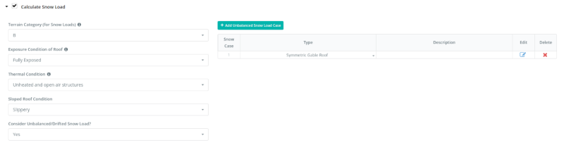
Figure 8. Snow load parameters.
Generating the snow load, the balanced roof snow load is equal to 0.23 kPa.
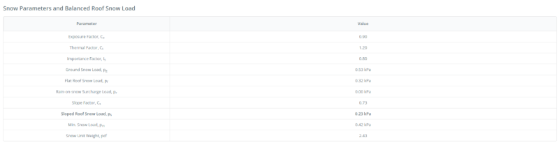
Figure 9. Balanced snow load result.
For the unbalanced case, we need to consider loading on one side (p1) equal to 0 and the other (p2) equal to 0.42 kPa.
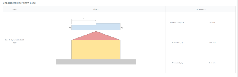
Figure 10. Unbalanced snow load result for gable roof.
Therefore, the snow load on the purlins and roof trusses is as follows:
\({W}_{truss,balanced} = 0.23 kPa (3.33m) = 0.766 kN/m \)
\({W}_{truss,unbalanced p1} = 0 kN/m \)
\({W}_{truss,unbalanced p2} = 0.42 kPa (3.33m) = 1.399 kN/m \)
Same with live load, the snow load is acting on the horizontal projection of the effective area and should be converted into an inclined load acting on the top chord of the roof truss. Therefore:
\({W}_{truss,balanced} = 0.766 kN/m / cos(29.745°) = 0.882 kN/m \)
\({W}_{truss,unbalanced p1} = 0 kN/m \)
\({W}_{truss,unbalanced p2} = 1.399 kN/m /cos(29.745°) = 1.611 kN/m \)
Start Roof Truss Calculation with SkyCiv:
Roof Truss Design
Using the SkyCiv S3D, we can analyze the roof truss: 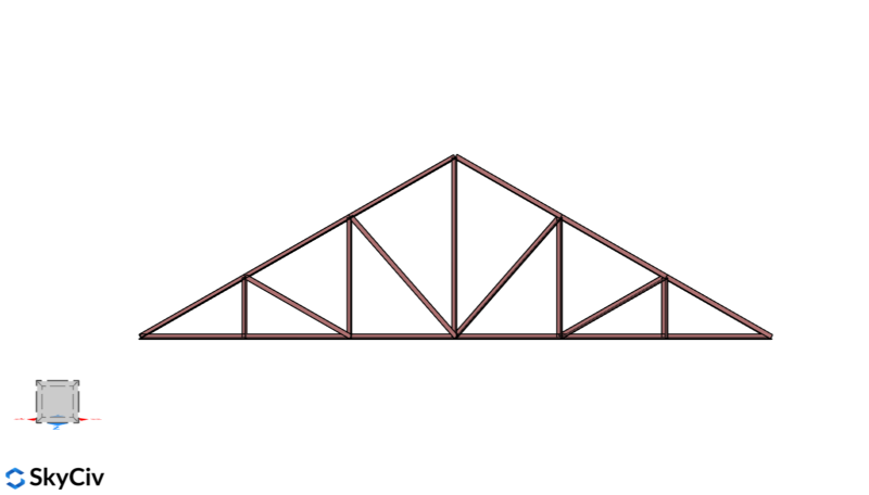
We will assume that the roof truss is simply supported and will be analyzed in 2D by adding supports on each node with code RRFRRR to only fix the Z-axis displacement. The initial section we will be using is an AISC L shape – 2.5”x2.5”x3/16”. In addition, the members are modeled as truss – where the node fixity are released for the local Y- and Z-axis. Applying the roof loads and multiplying each load that we calculated above to the member length to convert it to nodal loads. All these calculations can be performed using our Truss Structure Calculator.
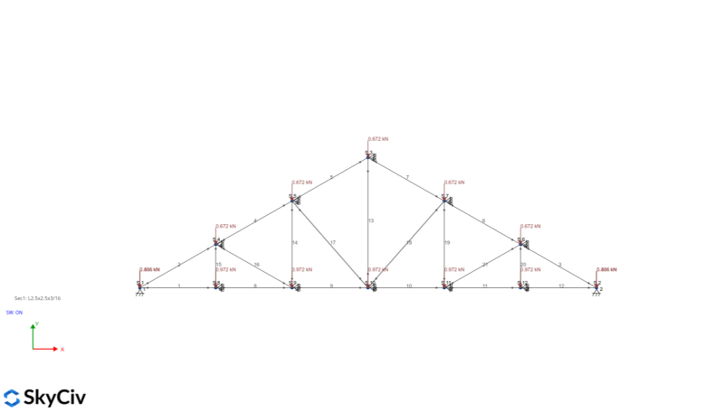
Dead Load
Live Load

Wind+ Load
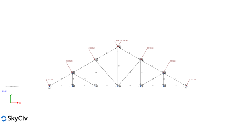
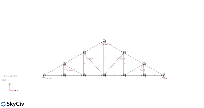
Wind- Load
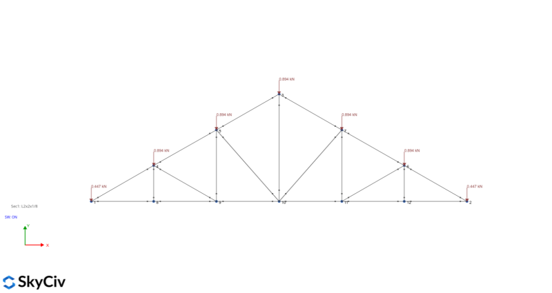
Snow Load – balanced case
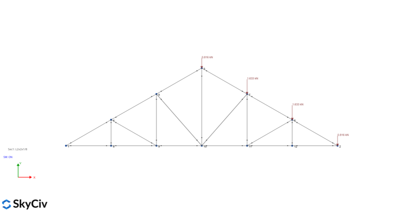
Snow Load – unbalanced case
Using the Load Combination for ASCE 7-16 LRFD, the forces needed to design the member can be generated:
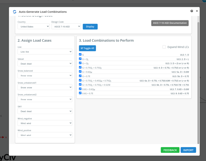
Figure 18. ASCE 7-16 LRFD Load Combination.
Since we are using an angle section, we need to also consider buckling. Solving the model by clicking Linear Static + Buckling in the Solve button, we can get the following envelope forces:
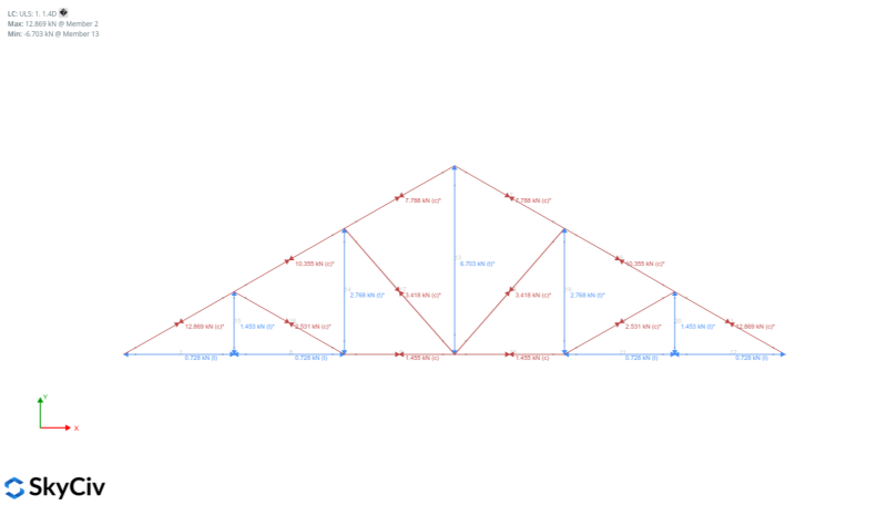
Figure 19. Axial load result from the analysis.
From these loads, we can already design the roof truss member using the SkyCiv Member Design Module and selecting AISC 360-16 LRFD:
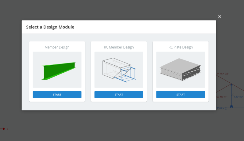
Figure 20. Member design modules in S3D.
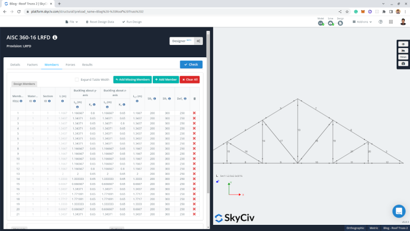
Figure 21. AISC 360-16 LRFD Member Design.
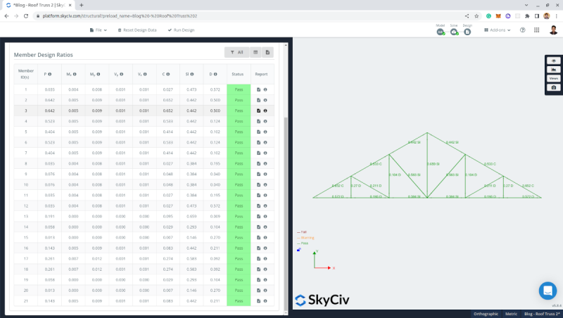
Figure 22. Member design results using L2.5”x2.5”x3/16” in accordance to AISC 360-16 LRFD.
We can see that the section we used – L2.5”x2.5”x3/16” – is adequate and passed the design checks.
Using the Bill of Materials add-on we can set a price per kg for the section. In this model, setting unit cost per kg of steel to $0.8:
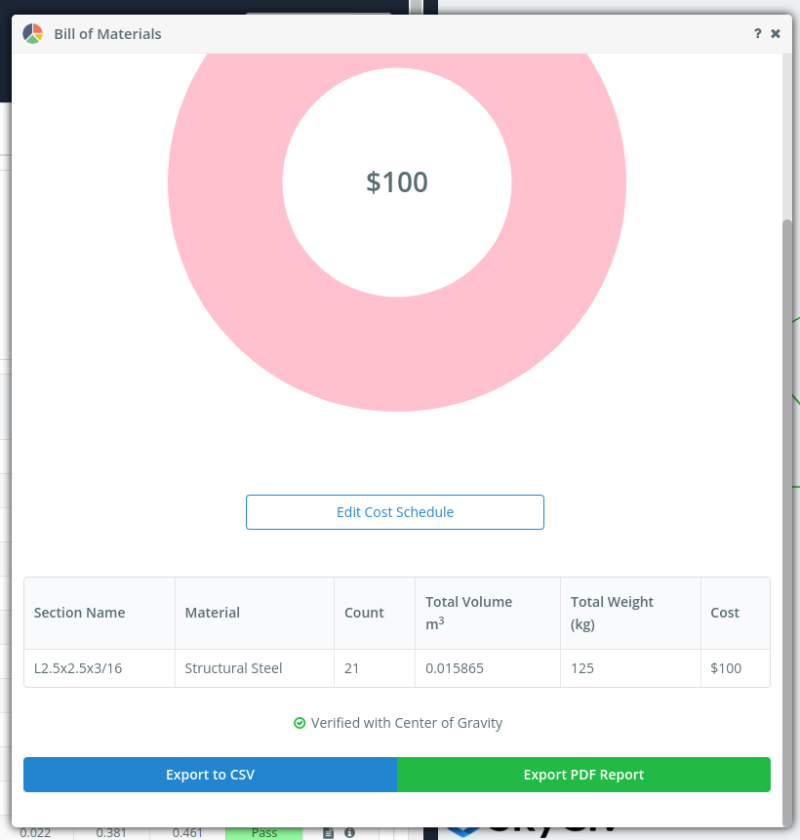
Figure 23. Bill of material using L2.5”x2.5”x3/16” for the roof truss.
To further increase the economy of the design, we can use the optimizer. We just need to set the criteria, and the optimizer will automatically select the most economical section for the roof truss.
Using the default settings:
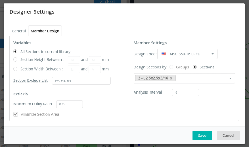
Figure 24. Options for SkyCiv S3D member design optimizer.
The optimizer result is then suggesting that we can use L2x2x1/8 for this truss. Once we commit the changes, it will automatically recalculate the model and check if the section is adequate.
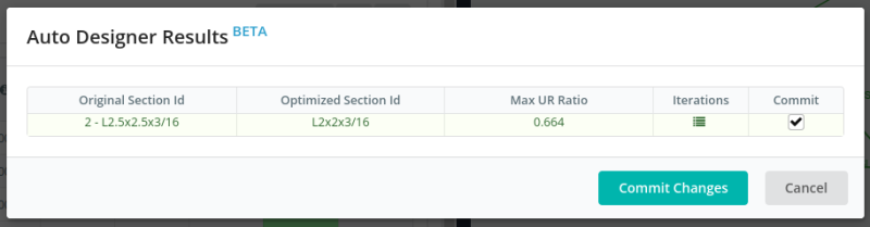
Figure 25. Generated optimized section for the roof truss using the SkyCiv S3D member design optimizer.
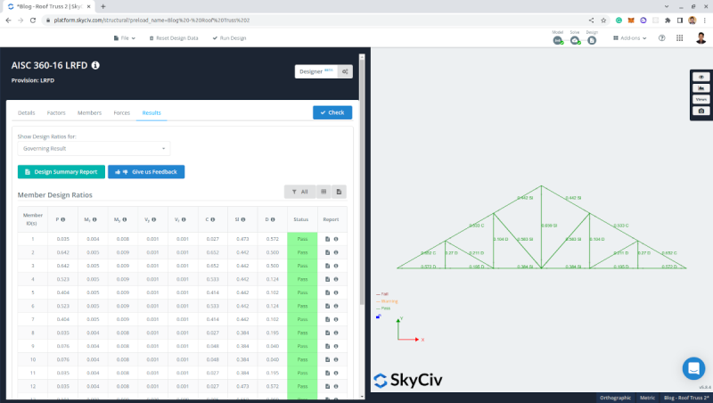
Figure 26. Member design result using the optimized section for the roof truss.
Checking the Bill of Materials again, we can see that the weight of the steel need dropped from 125kgs to 100kgs saving $20!
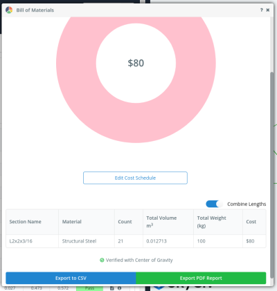
Figure 27. Bill of materials using the optimized section for the roof truss.
SkyCiv Load Generator
All of the above processes can be achieved in just a few clicks using SkyCiv Load Generator.
You can try it for free with our Free Online Wind Load Calculator. It is now available as a Standalone version or as part of our Structural 3D Software. So sign up today to get started!

Structural Engineer, Product Development
MS Civil Engineering
References:
- American Society of Civil Engineers. (2017, June). Minimum design loads and associated criteria for buildings and other structures. American Society of Civil Engineers.
- Google Maps