Spread Footing Design Workflow
Footings are structural members used to support columns and other vertical elements to transmit their superstructure loads to the underlying soils.
Figure 1 illustrates the design workflow process, which the SkyCiv Foundation adapts workflow process. Wherein these checks such as (1) Soil Bearing, (2) Shear, (3) Flexural, (4) Development Length, (5) Uplift, and (6) Stability Checks are important parameters required to satisfy the result without exceeding the allowable utility ratio.
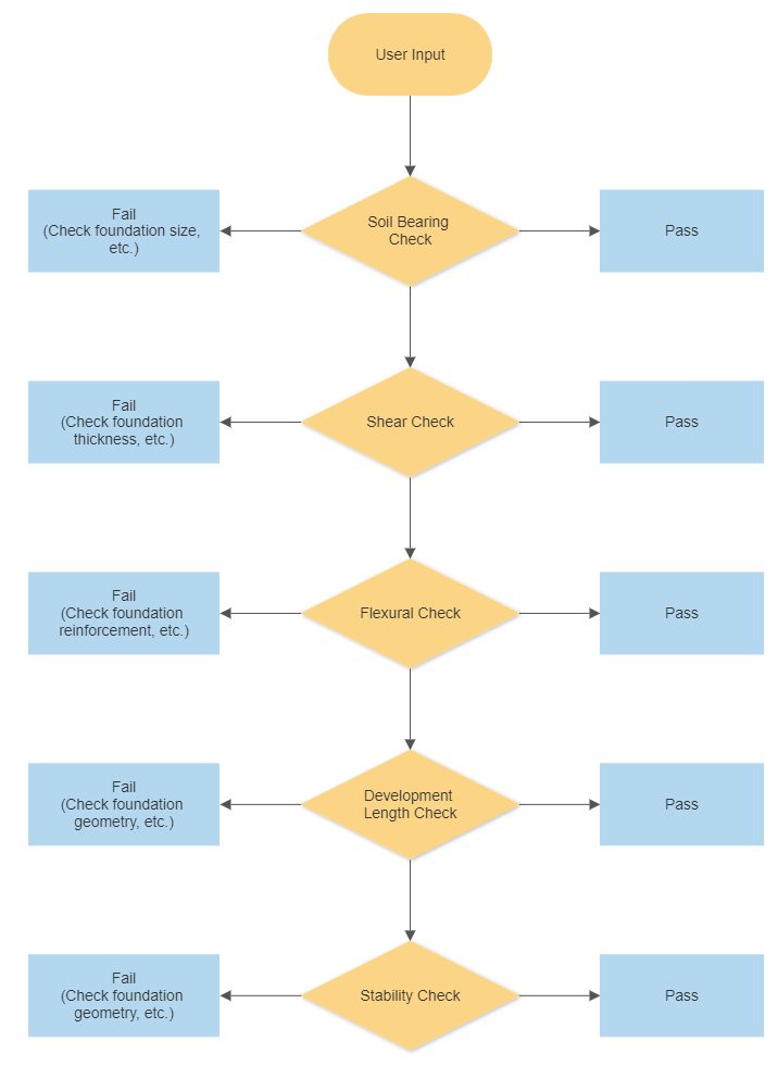
Figure 1: Workflow of SkyCiv Foundation.
How to Design Spread Footing
This section discusses the design procedure of spread footing in reference to American Concrete Institute 318-2014.
Soil Bearing Check
The Soil Bearing Check mainly determines the geometric dimensions of an isolated footing from the superstructure (service or unfactored) loads. The actual bearing pressure mainly determined by the equation below:
When the eccentricities exceeded the kern, the detailed article on bearing pressure pattern is explained here.
To satisfy the foundation geometric dimensions, the allowable bearing capacity of the soil should greater than the governing base pressure under the footing.
\( \text{Allowable Bearing Capacity} > \text{ Actual (Governing) Bearing Pressure on the Foundation} \)
Note: No tension in Bearing Pressure in the Foundation Design.
Shear Check
The Shear Check determines the thickness or depth of the foundation based on the shear load induced from the superstructure loads. There are two primary shear checks, as follows:
- One-way (or Beam) Shear
- Two-way (or Punching) Shear
One Way (or Beam) Shear
The critical section for one-way shear extends across the width of the footing and is located at a distance d from the face of a column.
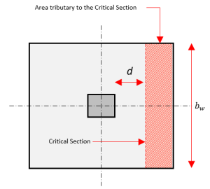
Figure 2: One-way Shear
Imperial (psi)
\( V_{c} = 2 \lambda \sqrt{ f^{‘}_{c} } b_{w} d \)
Metric (MPa)
\( V_{c} = 0.17 \lambda \sqrt{ f^{‘}_{c} } b_{w} d \)
To satisfy the One Way (or Beam) Shear, the \( V_{c} \) should not be greater than \( V_{u} \).
\( \phi V_{c} > V_{u} = \text{ Actual (Governing) Shear of the Foundation} \)
Two Way (or Punching) Shear
The critical section for two-way shear design is located in \( \frac{d}{2} \) away from a concrete column face. Where \( V_{c} \) equation is defined as follows:
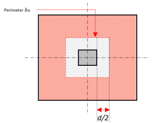
Figure 3: Two-way Shear
Imperial (psi)
\( V_{c} = \left( 2 + \frac{4}{\beta} \right) \lambda \sqrt{ f^{‘}_{c} } b_{o} d \)
\( V_{c} = \left( \frac{\alpha_{s} d }{ b_{o} } + 2 \right) \lambda \sqrt{ f^{‘}_{c} } b_{o} d \)
\( V_{c} = 4 \lambda \sqrt{ f^{‘}_{c} } b_{o} d \)
Metric (MPa)
\( V_{c} = 0.17 \left( 1 + \frac{2}{\beta} \right) \lambda \sqrt{ f^{‘}_{c} } b_{o} d \)
\( V_{c} = 0.083 \left( \frac{ \alpha_{s} d }{ b_{o} } + 2 \right) \lambda \sqrt{ f^{‘}_{c} } b_{o} d \)
\( V_{c} = 0.33 \lambda \sqrt{ f^{‘}_{c} } b_{o} d \)
The governing \( V_{c} \) will be taken as the least value.
To satisfy the Two Way (or Punching) Shear, the \( V_{c} \) should not be greater than \( V_{u} \).
\( \phi V_{c} > V_{u} = \text{ Actual (Governing) Shear of the Foundation} \)
Flexural Check
The Flexural Check determines the required reinforcement of the foundation based on the moment or bending load induced from the superstructure loads. The Design procedure for moment strength considers a one-way flexural member first in one principal direction.
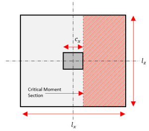
Figure 4: Critical Moment Section Line
Step 1. Calculate the Actual Moment on the foundation \( M_{u} \).
\( M_{u} = q_{u} \left( \frac{ l_{x} – c }{ 2 } \right) l_{z} \frac{ l_{x} – c }{ 2 } \)
Step 2. Calculate the required minimum reinforcement of the foundation
Step 3. Calculated the Depth of equivalent rectangular stress block, a.
\( a = \frac{ A_{s} f_{y} }{ 0.85 f_{c}^{‘} l_{z} } \)
Step 4. Calculate the Moment Capacity of the foundation \( \phi M_{n} \).
\( \phi M_{n} = \phi A_{s} f_{y}\left( d – \frac{a}{2} \right) \)
To satisfy the flexural requirement, the \( \phi M_{n} \) should not be greater than \( M_{u} \)..
\( \phi M_{n} > M_{u} \)
Development Length Check
The Development Length Check determines the shortest embedment length required for a reinforcing bar to develop its full yield strength in concrete.
Stability Check
There are two main types of Stability Checks in the foundation, as follows:
- Overturning
- Sliding
Overturning Check
Overturning Check is a stability check against the Moment of the superstructure load. Generally, this factor of safety for the overturning moment is 1.5-3.0.
\( \text{Overturning Factor of Safety} < \frac{ \sum M_{R} }{ \sum M_{OT} } \)
Note:
- \( \sum M_{R} \) – Resisting Moment
- \( \sum M_{OT} \) – Overturning Moment
Sliding Check
Sliding Check is a stability check against Horizontal Force induced by the superstructure load. Generally, this factor of safety for the overturning moment is 1.5-3.0.
\( \text{Sliding Factor of Safety} < \text{Sliding Force} \)
Uplift Check
Checks the governing axial load acting on the footing. Sums all vertical loads including the user load and self-weights of the column, footing slab, soil, and buoyant force. If the column experiences an upward force, the self-weights specified must counterbalance the upward force; otherwise, the design risks failure due to instability.
This article explains the primary adjustment when the SkyCiv Foundation users encounter this failure check.
- Soil Bearing Check is mainly influenced by the spread footing dimension which is subjected to the superstructure (unfactored) loads and allowable soil pressure.
- Shear Check is mainly influenced by the depth of the spread footing where the spread footing performs one-way and two-way checks.
- Flexural Check is mainly influenced by the reinforcement schedule of the spread footing.
- Development Length Check and
- Stability Checks are mainly influenced by the spread footing dimensions.
Based on the information above, those adjustments will increase design capacity per checks of the spread footing.
Please note that some parameters such as materials strength, factor, and subjected loads are also part of increased design capacity influence.
Design Code Modules
The SkyCiv Foundation have these currently available design codes:
- American Code : ACI 318-14
- Australian Standard : AS 3600 (2009 & 2018)
- European : Eurocode
- Canadian: CSA 2014
Latest Update
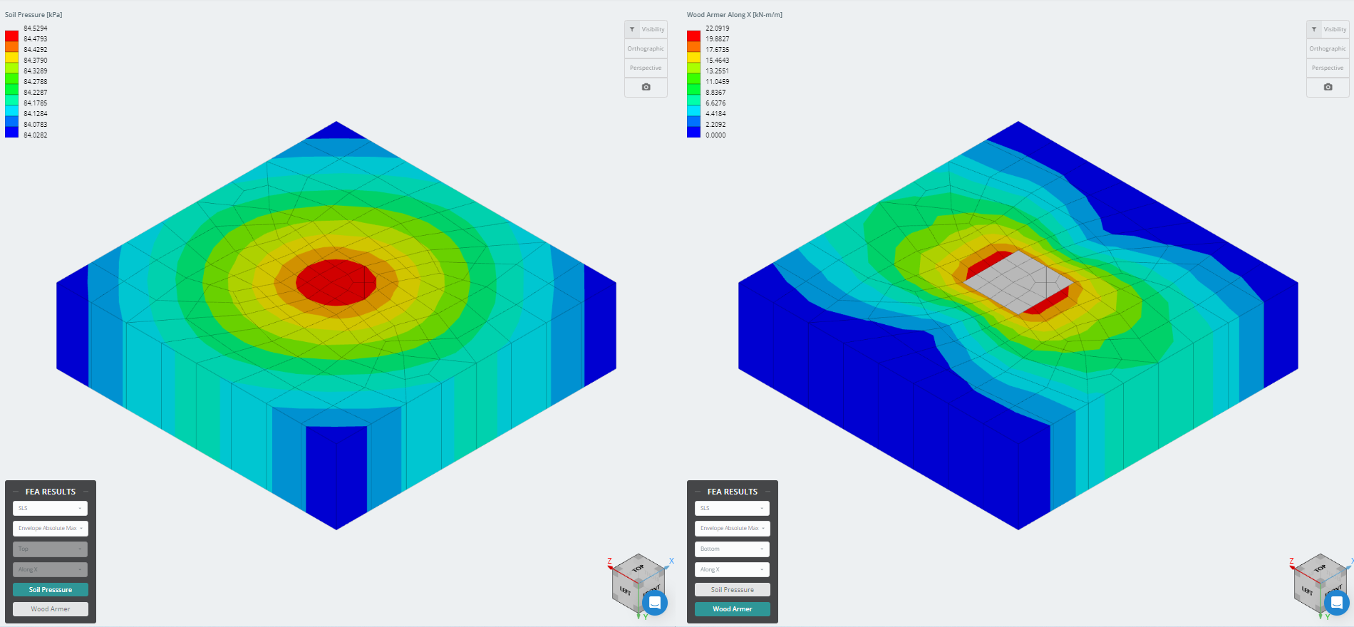
The latest version of the foundation module is now integrated with Finite Element Analysis (FEA), which offers a more powerful soil pressure analysis and introduces wood armer analysis to be used for a much more detailed flexural check. FEA results for the soil pressure and wood armer moments can be viewed in 3D and were added to the reports.
References
- Building Code Requirements for Structural Concrete (ACI 318-14) Commentary on Building Code Requirements for Structural Concrete (ACI 318R-14). American Concrete Institute, 2014.
- McCormac, Jack C., and Russell H. Brown. Design of Reinforced Concrete ACI 318-11 Code Edition. Wiley, 2014.
- Taylor, Andrew, et al. The Reinforced Concrete Design Handbook: a Companion to ACI-318-14. American Concrete Institute, 2015.
- Darwin, David and Dolan, Charles. Design of Concrete Structures 16 Edition. McGrawHill, 2021.
Get Started with SkyCiv Foundation today!
Our free tool allows users to perform load-carrying calculations without downloading or installing! Launch the Foundation Design and try it today! It’s easy to get started, but if you need more help, be sure to visit our documentation or get in touch with us!
Not a SkyCiv User?
Sign up for a Free 14 Day Trial to get started today!

Product Developer
BSc (Civil), MSc (Civil)