SkyCiv introduces the seismic load calculation for buildings using ASCE 7-16 Equivalent Lateral Force procedure. In addition to the parameters for wind and snow loads, the seismic load calculation uses seismic parameters obtained from U.S. Geological Survey (USGS) Web Services. Users will get the following data that can be modified to get the most appropriate seismic load for the structure:
- Long-period transition period \( {T}_{L} \)
- Design spectral response acceleration parameter at short period, \( {S}_{DS} \)
- Design spectral response acceleration parameter at 1s period, \( {S}_{D1} \)
- Mapped maximum considered earthquake spectral response acceleration parameter, \( {S}_{1} \)
With a Professional Account or by purchasing the standalone Load Generator module, you can use all the features of this calculation as long as you want. You can purchase the standalone module through the link below.
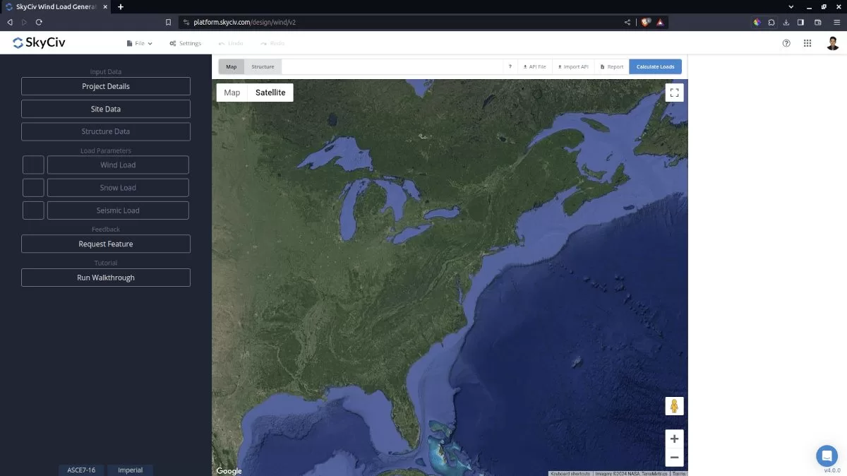
Figure 1. SkyCiv Load Generator UI
Video Tutorial
Site Data
Together with the wind speed and ground snow load data, users can get the seismic parameters for the location obtained from USGS Web Services by defining the Risk Category of the structure, Site Class, and then the location:
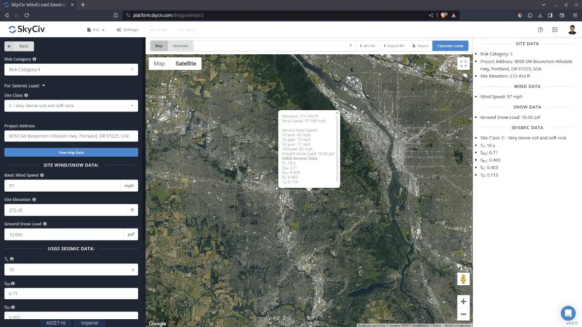
Figure 2. ASCE 7-16 additional parameter (site class) for obtaining site seismic parameters.
Users can modify the parameters obtained from USGS Web Services to obtain the most appropriate seismic load for the structure.
Structure Data
Next step is to define first the Structure you are analyzing. Currently, Building, Solar Panels, and Rooftop Equipment are supported in ASCE 7-16.
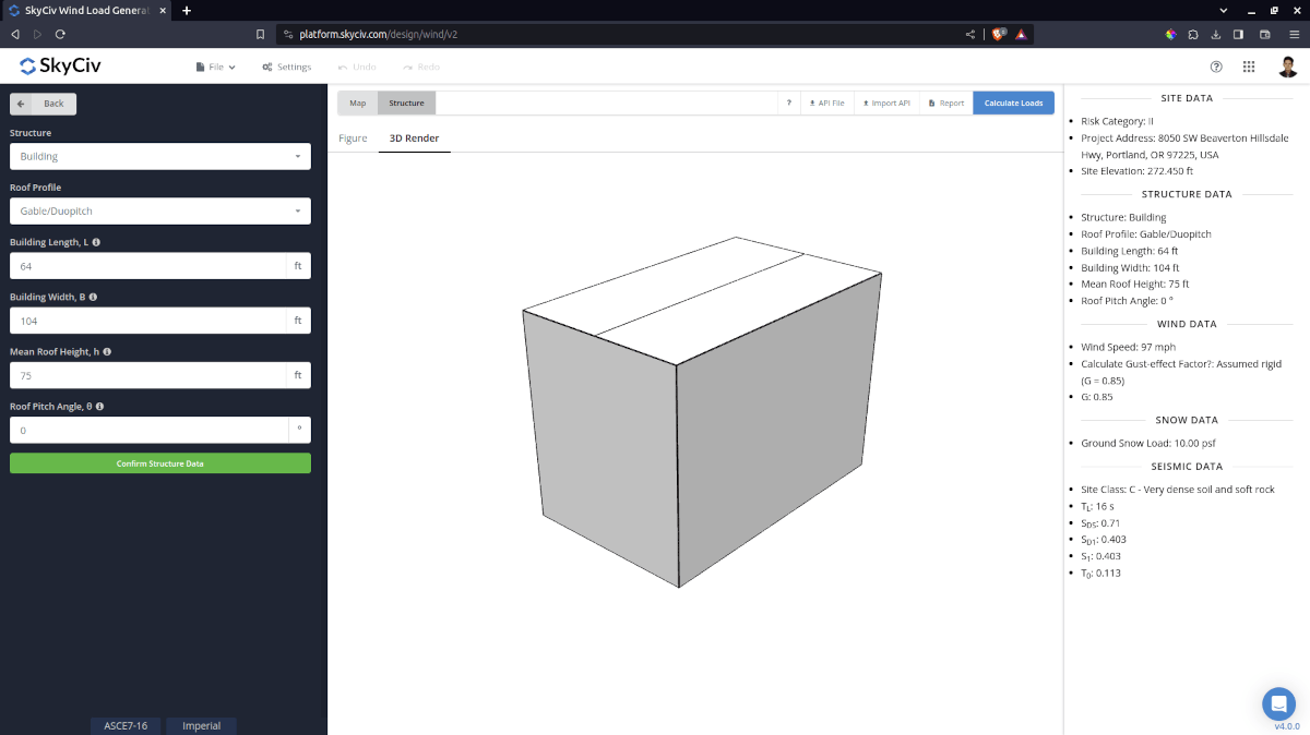
Figure 3. Structure data input for buildings.
Seismic Data
To proceed with our seismic load calculation, we need to check the checkbox first beside the Seismic Load button. By default, this is checked when the all site seismic data have been defined.
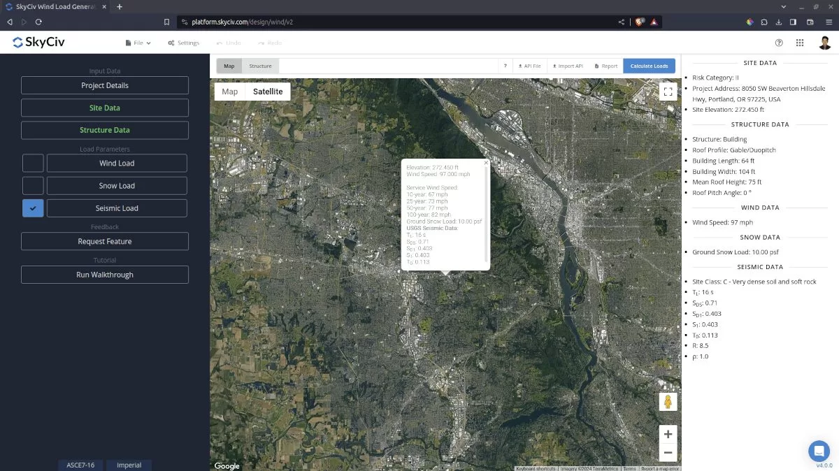
Figure 4. Checkbox for Seismic Load Data.
For Buildings
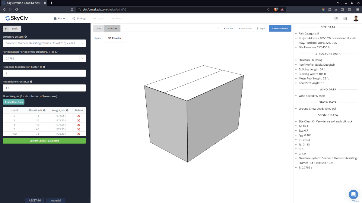
Figure 5. Seismic parameters for buildings.
The seismic parameters needed (for building) to be defined are the following:
- Structure system – for determining the values of \({C}_{t} \) and \(x \) which will be used in calculating the approximate fundamental period of the structure \({T}_{a} \)
- Approximate fundamental period of the structure \({T}_{a} \) – can be user-defined to more appropriate seismic load calculation. Can be calculated using the SkyCiv S3D – Dynamic Frequency Analysis.
- Response Modification Factor \( R \) – default value is 3.5 and should be modified for more appropriate seismic results
- Redundancy factor, \( ρ \) – default value is 1.0 and can be modified. Used in diaphragm forces calculation
- Floor Weights – used for the vertical distribution of base shear and for diaphragm forces. Data per level required are: Level (for designation), Elevation, and Weight
The approximate fundamental period of the structure is automatically calculated as guide for the users when the “Structure system” dropdown is changed. Users are free to edit this value which is affect the corresponding calculated base shear for the structure.
For Rooftop Equipment/Structures
The seismic load calculation for Rooftop Equipment/Structures uses Chapter 13 Seismic Design Requirements for Nonstructural Components of ASCE 7-16.
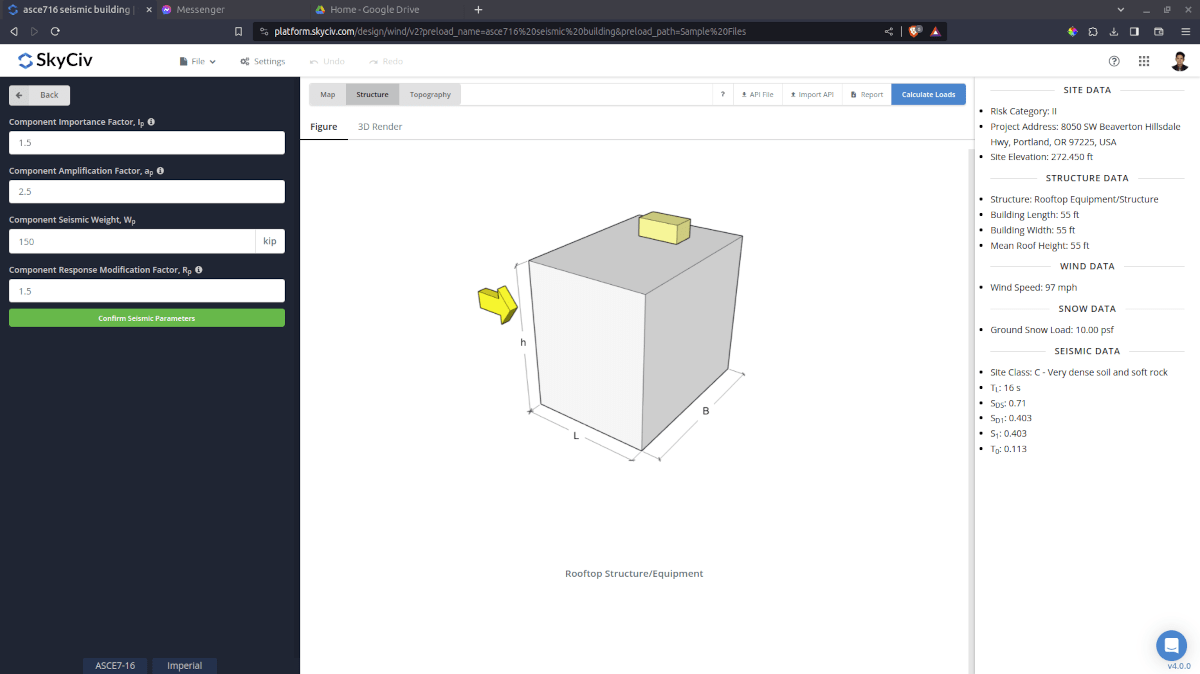
Figure 6. Seismic parameters for rooftop equipment/structure.
The seismic parameters needed (for rooftop equipment) to be defined are the following:
- Component Importance Factor \({I}_{p} \) – Refer to Section 13.1.3 of ASCE 7. Default value is 1.5.
- Component Amplification Factor, \({a}_{p} \) – Refer to Tables 13.5-1 or 13.6-1 of ASCE 7. Default value is 2.5.
- Component Response Modification Factor \( {R}_{p} \) – Refer to Tables 13.5-1 or 13.6-1 of ASCE 7. Default value is 1.5.
- Component Seismic Weight, \( W_{p} \) – used in calculating the design base shear.
For Solar Panels
Rooftop Solar Panel
Similar to Rooftop Equipment, the calculation uses Chapter 13 Seismic Design Requirements for Nonstructural Components of ASCE 7-16.
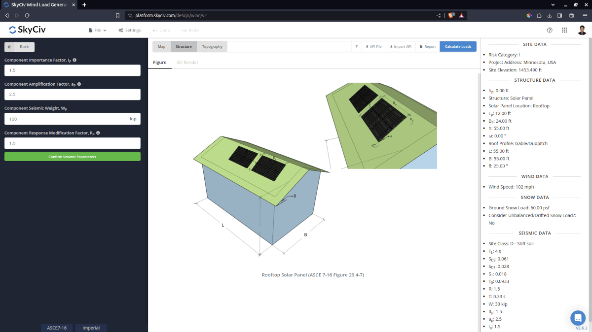
Figure 7. Seismic parameters for rooftop solar panel.
The seismic parameters needed (for rooftop solar panel) to be defined are the following:
- Component Importance Factor \({I}_{p} \) – Refer to Section 13.1.3 of ASCE 7. Default value is 1.5.
- Component Amplification Factor, \({a}_{p} \) – Refer to Tables 13.5-1 or 13.6-1 of ASCE 7. Default value is 2.5.
- Component Response Modification Factor \( {R}_{p} \) – Refer to Tables 13.5-1 or 13.6-1 of ASCE 7. Default value is 1.5.
- Component Seismic Weight, \( W_{p} \) – used in calculating the design base shear.
Ground-mounted Solar Panel
For ground-mounted solar panel, the seismic load calculation implemented is based on Chapter 15 Seismic Design Requirements for Nonbuilding Structures of ASCE 7-16.
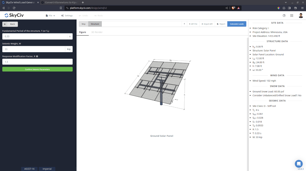
Figure 8. Seismic parameters for ground-mounted solar panel.
The seismic parameters needed (for ground-mounted solar panel) to be defined are the following:
- Approximate Fundamental period of the structure \({T}_{a} \) – user-defined value. Can be calculated using the SkyCiv S3D – Dynamic Frequency Analysis.
- Response Modification Factor \( {R}_{p} \) – Refer to Tables Refer to Tables 15.4-1 and 15.4-2 of ASCE 7. Default value is 1.5.
- Seismic Weight, \( W \) – used in calculating the design base shear.
After all these parameters are defined, the next step is to click the Calculate Loads on the upper right side of the UI.
Results
Once all the parameters are defined, clicking the Calculate Loads button will give a result as shown below. The seismic load results will show the parameters in calculating the seismic load as shown below. The summarized results are shown on the right side of the screen. Other results are shown on the detailed report.
Buildings
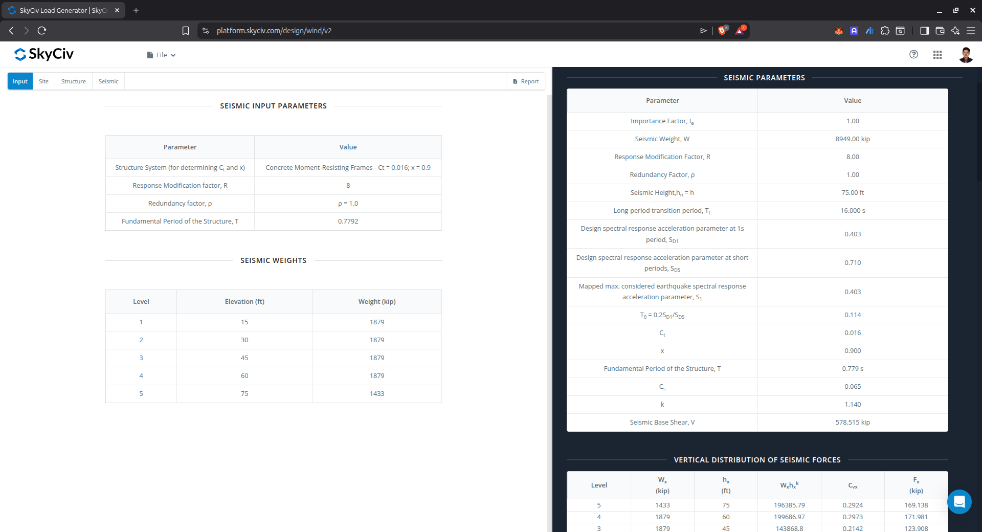
Figure 9. Seismic input parameters used in the calculation and the calculated and base shear.
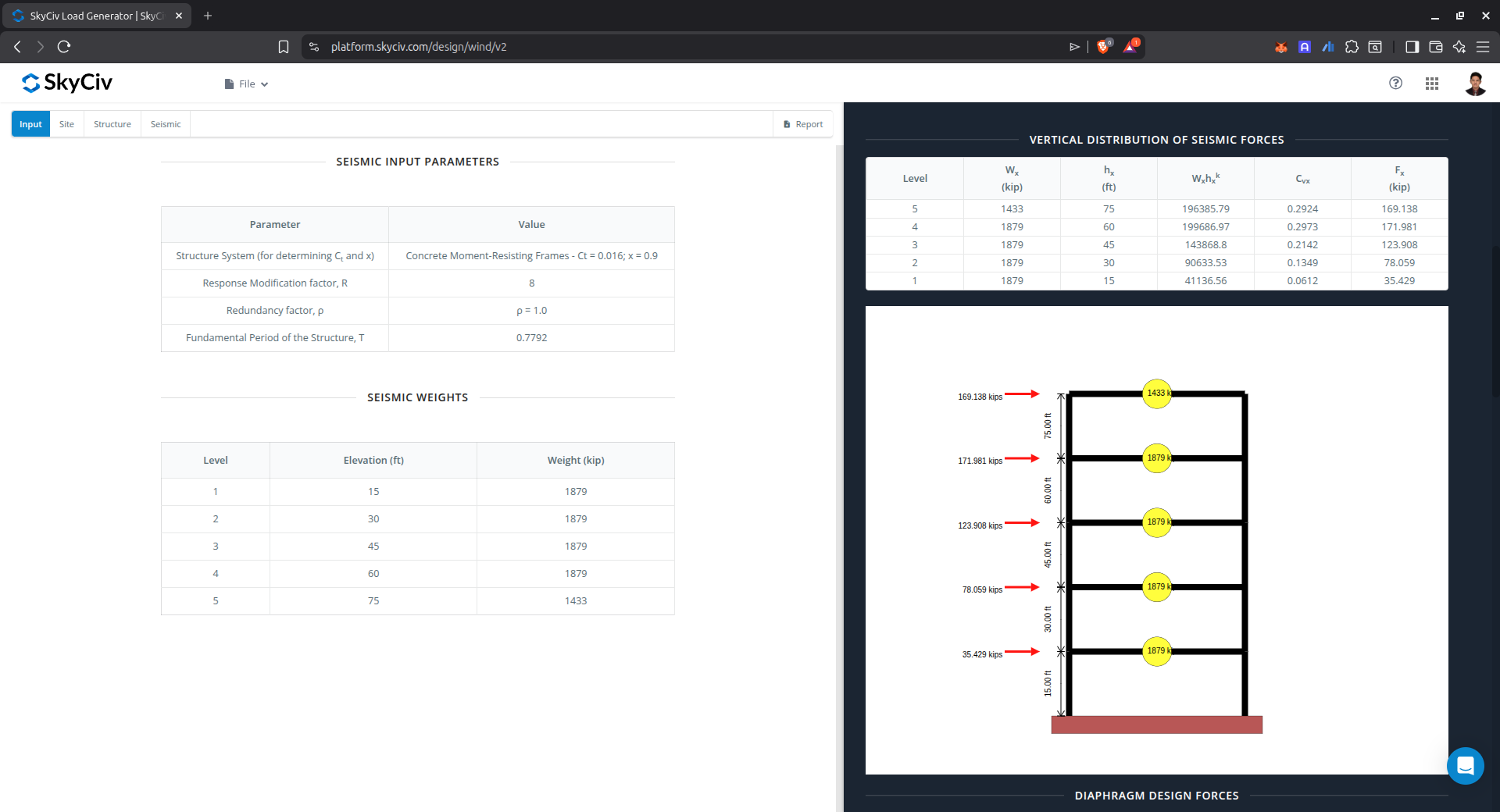
Figure 10. Calculated seismic forces using the equivalent lateral force procedure.
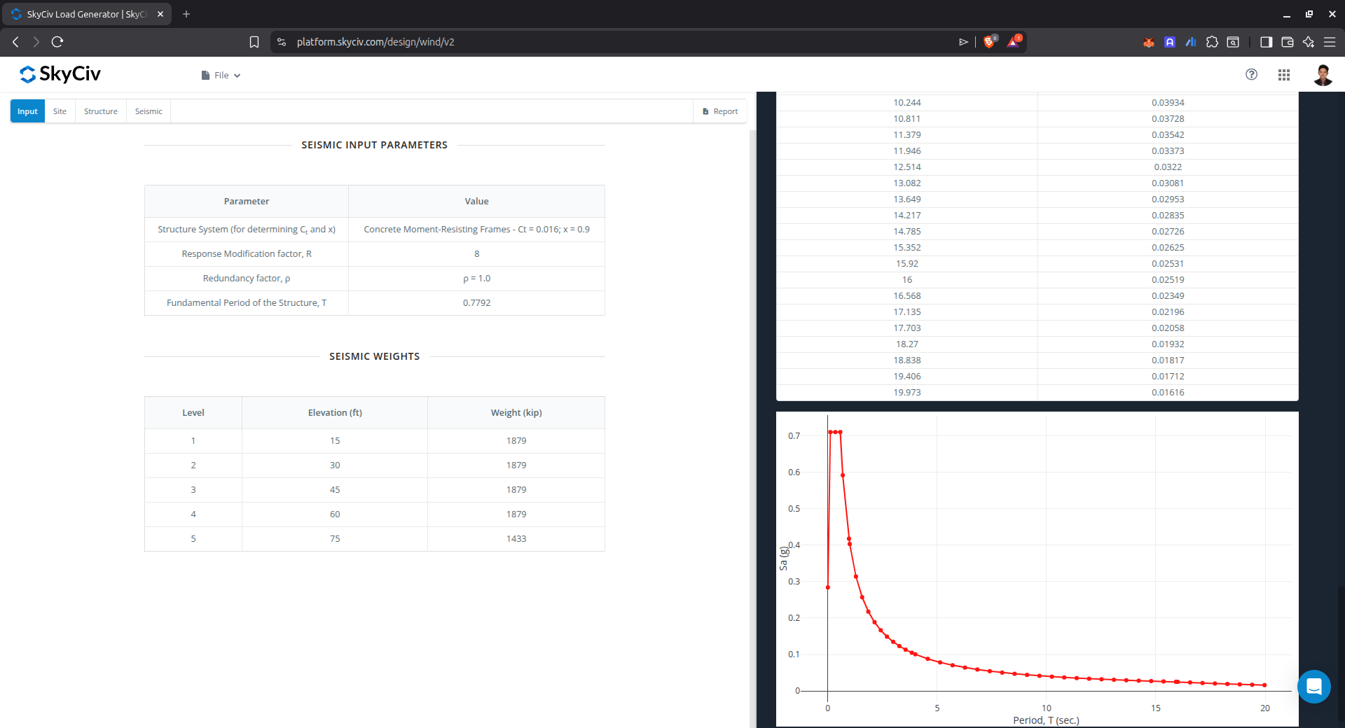
Figure 11. The generated Design Response Spectrum for the structure.
Rooftop Equipment/Structures
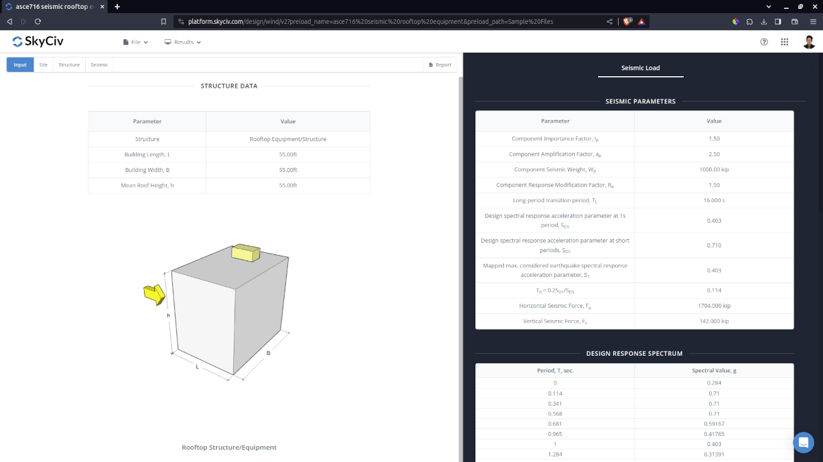
Figure 12. Seismic input parameters and the calculated design seismic forces for rooftop equipment/structures.
Solar Panels
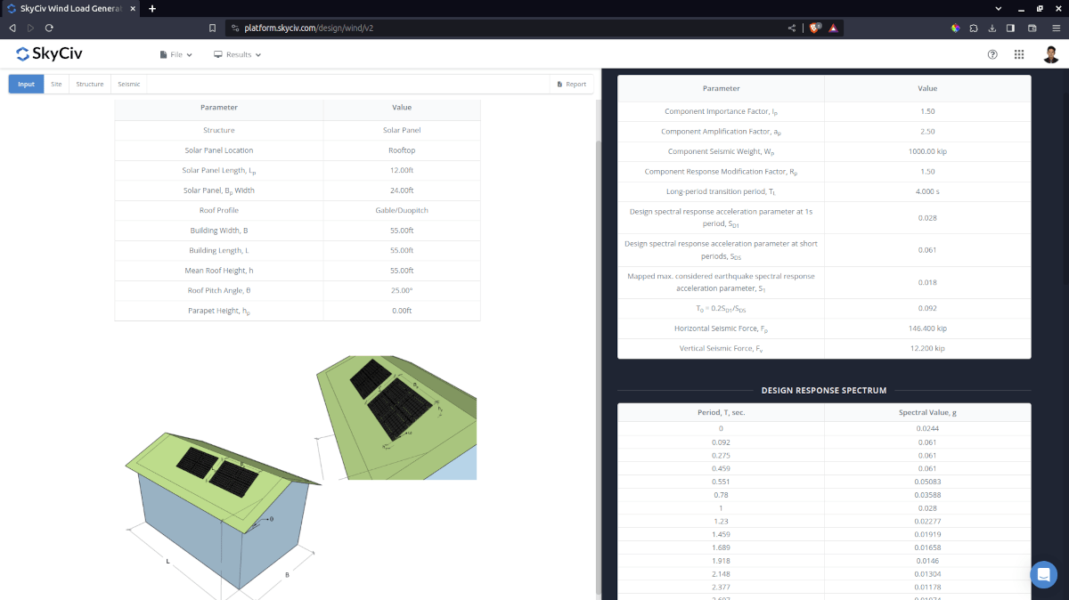
Figure 13. Seismic input parameters and the calculated design seismic forces for rooftop solar panel.
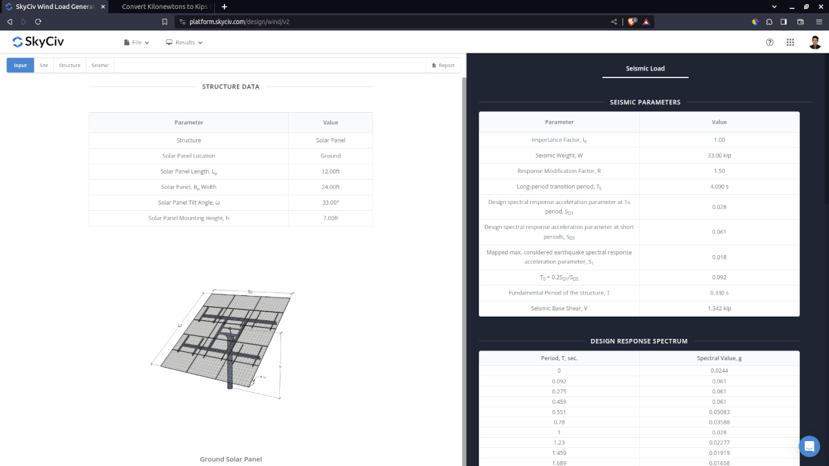
Figure 14. Seismic input parameters and the calculated design seismic force for ground-mounted solar panel.
Detailed Calculation
The detailed seismic load calculations can be accessed only by Professional account users and those who purchased the standalone load generator module. All the parameters and assumptions used in the calculation are displayed on the report to make it transparent to the user. You can download a sample detailed calculation thru the following links:
- ASCE 7-16 Seismic Load – Buildings
- ASCE 7-16 Seismic Load – Ground Solar Panel
- ASCE 7-16 Seismic Load – Rooftop Solar Panel
- ASCE 7-16 Seismic Load – Rooftop Equipment/Structure
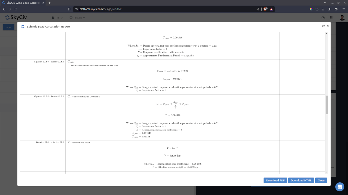
Figure 15. Detailed seismic load calculation generated from SkyCiv Load Generator.
For additional resources, you can use these links for reference:
- ASCE 7-16 Seismic Load Calculation Example Using Equivalent Lateral Force Procedure
- How to apply wind loads to a structure in S3D