
What is a Shear Connection?
A shear connection is a joint that transfers shear force between two members without transferring meaningful moment. If a beam carries internal shear force, that force passes through the connection into the supporting column as axial force. Shear connections behave as a pin (FFFFFR in SkyCiv Structural 3D), unlike moment connections, which hold the end rotation.
In AISC 360-16 terms this is a simple connection: it is assumed to rotate freely and to carry negligible moment. AS 4100:2020 calls the equivalent arrangement simple construction. A semi-rigid joint is a third case, with real but partial rotational stiffness, and it has to be modelled that way rather than treated as simple.
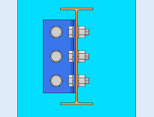
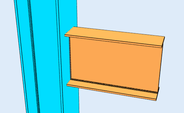
A plate or angle carries the force between the two members. In the example above, any downward load on the beam passes into the supporting member through the angle. Because nothing restrains the beam flanges, the joint can rotate, which is what makes it a shear connection rather than a moment connection.
Shear connections are the most common connection in steel framing. Where a frame is braced, the bracing provides the lateral stability, so moment connections are needed only where the frame relies on frame action. That is why most designers reach for a shear connection wherever the analysis allows: they are simpler to fabricate and cheaper to erect.
SkyCiv Connection Design checks shear connections to AISC 360-16 in both ASD and LRFD, and to AS 4100:2020.
Types of Shear Connections
Shear connections are named after the component that carries the load and where it sits. Which ones are available depends on the design code and on what the beam frames into, so the lists below are split that way.
Beam to I-section column, or beam to beam (AISC 360-16)
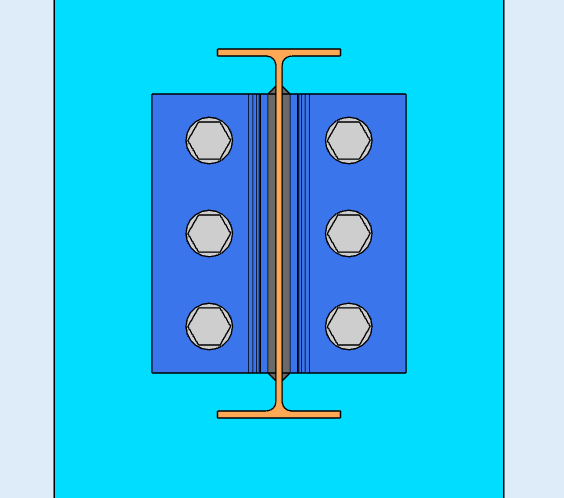
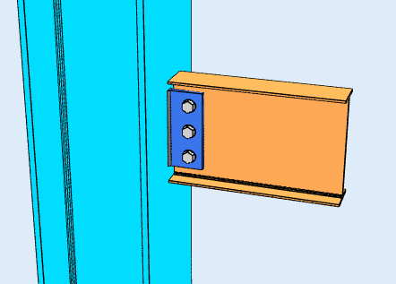
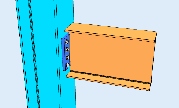
Six configurations, each available framing to the column flange, to the column web, or beam-to-beam through the web:
- Single Angle. One L-shaped bracket between the beam web and the support. The lightest option, and the most flexible, so it suits light loads.
- Double Angle. Angles on both faces of the beam web. The extra angle roughly doubles the bolt shear planes and makes the connection more forgiving during erection, which is why it is the workhorse for heavier beams.
- Single Plate. The shear tab. One plate, shop-welded to the support and bolted to the beam web. Usually the cheapest of the group, because there is one weld line and one bolt group.
- Double Plate. Plates on both faces of the web, used where a single plate cannot carry the shear or fit the required bolt group.
- End Plate. A plate welded to the beam end and bolted to the support. It needs the beam cut to length accurately, since the plate leaves no adjustment.
- Directly Welded Web. The beam web welded straight to the support, with no intermediate plate or angle. There are no bolts to check, but it needs field welding and gives up the erection tolerance a bolted detail provides.
Beam to HSS column (AISC 360-16)
Framing into a hollow section changes what fits, because there is no flange to bolt to and no access to the far side for a wrench. Five configurations are available:
- Single Angle and Double Angle
- Single Plate
- Single WT. A tee cut from a wide flange, its stem welded or bolted to the beam web and its flange to the column face.
- Seat Angle. An angle under the bottom flange carrying the beam in bearing, normally with a top clip for stability. Unlike the web-connected types, this one works off the flange.
AS 4100:2020
The Australian code covers beam-to-I-column and beam-to-beam framing, with four configurations:
- Web Side Plate, the AS 4100 name for the shear tab.
- Flexible End Plate
- Single Angle and Double Angle
AS 4100 coverage is shear only, and does not extend to HSS columns, channels, bracing or splices. Those are AISC 360-16.
What does the software check?
For a shear connection, the design runs both a detailing pass and a strength pass.
Detailing runs first and catches the geometry: bolt edge distances, bolt spacing (pitch and gage), tool clearances, and minimum and maximum plate dimensions, plus clash detection between plates, bolts and welds. A connection that fails here never reaches the solve. That is usually what you want, because the numbers do not matter if the detail cannot be built.
The strength checks then cover bolt shear, bolt bearing and tear-out, block shear rupture, plate yielding and rupture, weld throat stress, and the local limit states of the supporting member such as web local yielding. Every formula, design check and code reference is shown in full, with the clause numbers from AISC 360-16 or AS 4100:2020, so you can follow the calculation rather than take it on trust.
For the fastener side of this, see the documentation on bolts and welds.
What’s the difference between a Shear and Moment Connection?
A shear connection transfers shear only. A moment connection also transfers bending. Think of it as a hinge: a shear connection lets the beam end rotate, a moment connection holds it.
The distinction is a decision about the analysis model, not only about the detail. A shear tab designed as simple has to be flexible enough to actually rotate, and a moment connection has to be stiff enough to justify the fixity the frame model assumed.
| Shear Connection | Moment Connection | |
|---|---|---|
| Forces Transferred | Shear Only | Shear and Moment |
| Alternative names | Pinned, Hinge, Simple | Rigid, Fixed, Moment-resisting |
| AISC 360-16 term | Simple connection | FR or PR moment connection |
| Rotation | Allows Rotation | Restrains Rotation |
| Software Fixity Code | FFFFFR | FFFFFF |
SkyCiv Connection Design Software
The models and checks above are from SkyCiv Connection Design. It covers over 80+ pre-configured connection types, designs to AISC 360-16 (LRFD & ASD) and AS 4100:2020, and shows every formula, design check and code reference in full.
You can model the connection in 3D, swap bolts, welds or plates without losing your load data, produce 2D detail drawing sheets in CloudCAD, and export the 3D geometry to IFC for coordination in Revit, Tekla or Navisworks.
It runs entirely in the browser, with no downloads, updates or IT setup.
