Calculating Lateral Earth Pressure due to Surcharge Loads on Retaining Wall
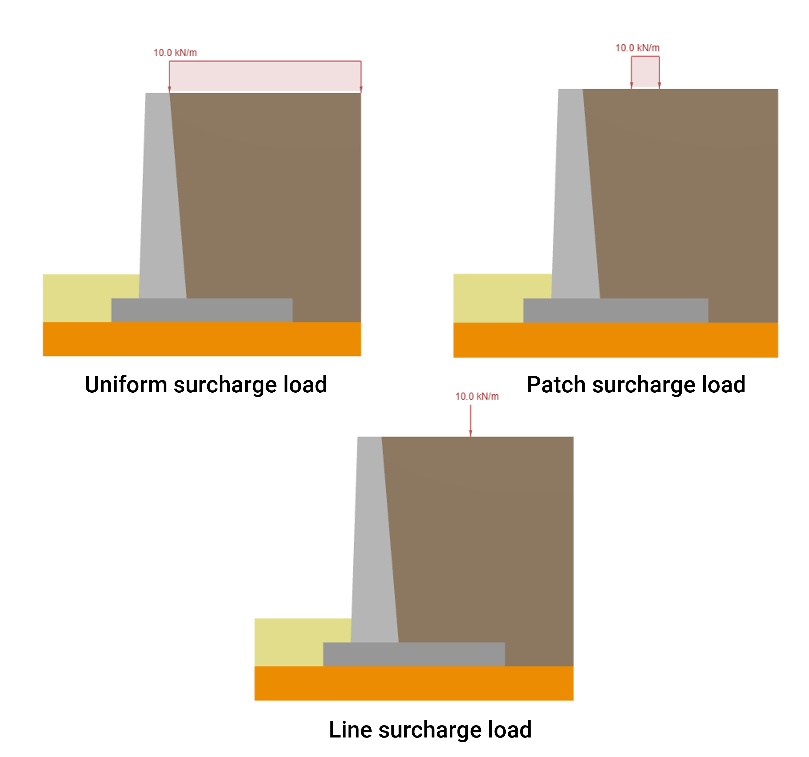
Soil zones on both sides of a Retaining Wall typically have some additional external loads applied. Those can be live surcharge loads on the retaining wall such as vehicular traffic, pedestrian traffic, and parking, or permanent loads such as protection systems against slope erosion, and adjacent structures. In this article, we will focus on how to calculate the lateral earth pressure acting on the backface of a Retaining Wall due to three types of superimposed or surcharge loads:
- Uniform load on the top of the soil
- Patch load on the top of the soil
- Line load on the top of the soil
Uniform Load
When the applied permanent or live surcharge load on the retaining wall is uniform and can be assumed that it is an infinite distributed load, the pressure exerted on the wall follows a uniform vertical distribution. For that reason, the location of the resultant is in the middle of the wall’s total height. In the case of a sloped backfill, the pressure distribution skews an angle equal to the backfill inclination. For this case, the calculation of the resultant goes as follows:
- For soil in at-rest condition:
\(P_{dist, \; at-rest} = K_{0} \cdot q \cdot H_{soil}\)
- For soil in active condition:
\(P_{dist, \; active} = K_{a} \cdot q \cdot H_{soil}\)
- For soil in passive condition:
\(P_{dist, \; passive} = K_{p} \cdot q \cdot H_{soil}\)
As mentioned before, since the distribution is uniform, the location of the resultant is located right in the middle of the soil height.
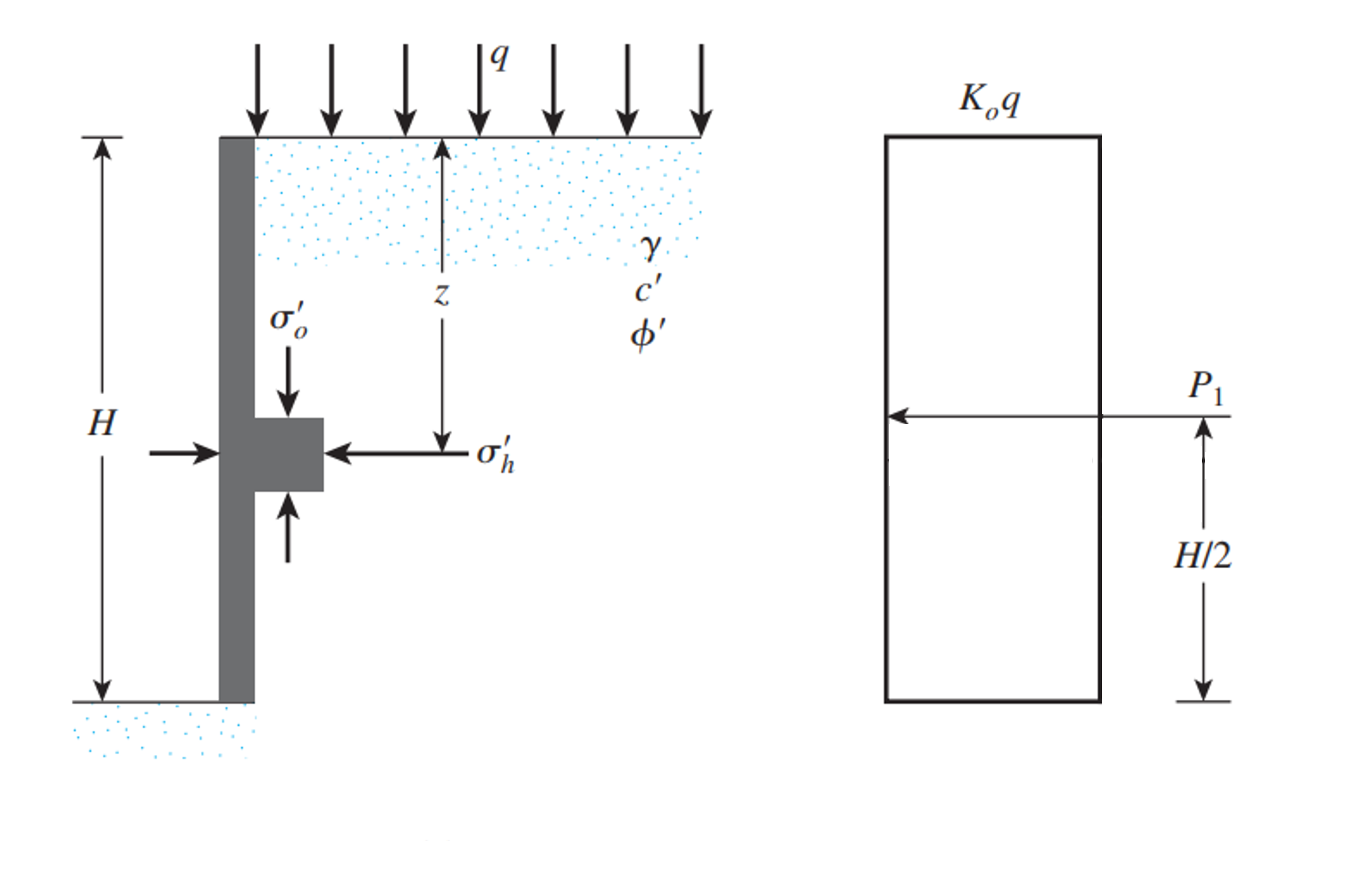
Adapted from: Das, B. M. (2010). Principles of Foundation Engineering, SI Edition. Chapter 7 Lateral Earth Pressure. Cengage Learning. Figure 7.3
Patch Load
For the case of a patch or strip surcharge load on a retaining wall, the total force per unit length may be expressed as:
\(P_{patch} = \frac{q}{90} [H(\theta_2-\theta_1)]\)
where,
\(\theta_1 = tan^{-1}(\frac{b’}{H}) (deg)\)
\(\theta_2 = tan^{-1}(\frac{a’ + b’}{H}) (deg)\)
This resultant force from the lateral earth pressure due to a patch or strip load is located at \(\bar{z}\) measured from the bottom of the pressure distribution, \(\bar{z}\) may be estimated using the following expression:
\(\bar{z} = H – [\frac{H^2(\theta_2-\theta_1) + (R-Q) – 57.3a’H}{2H(\theta_2-\theta_1)}]\)
Where \(R = (a’+b’)^2\cdot(90 – \theta_2)\) and \(Q = b’^2(90-\theta_1)\)
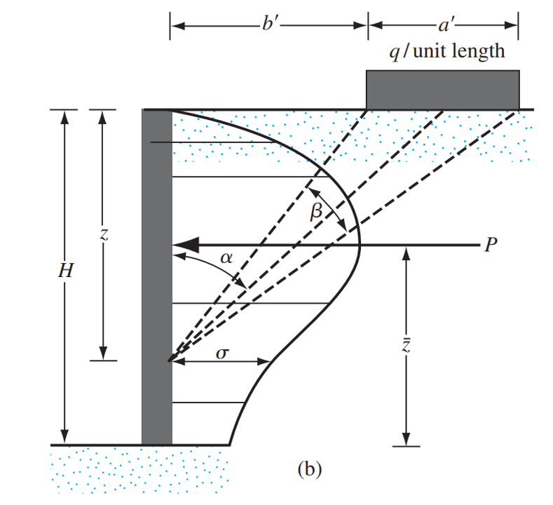
Taken from: Das, B. M. (2010). Principles of Foundation Engineering, SI Edition. Chapter 7 Lateral Earth Pressure. Cengage Learning. Figure 7.14
Line Load
Finally, for the case of a line surcharge load on a retaining wall, the stress on a retaining wall backface at any depth \(z\), can be expressed as:
\(\sigma = \frac{4q}{\pi H} \frac{a^2 b}{(a^2 + b^2)^2}\) for \(a > 0.4\)
\(\sigma = \frac{q}{H} \frac{0.203 b}{(0.16+ b^2)^2}\) for \(a \leq 0.4\)
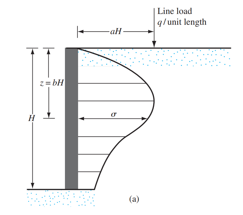
Taken from: Das, B. M. (2010). Principles of Foundation Engineering, SI Edition. Chapter 7 Lateral Earth Pressure. Cengage Learning. Figure 7.14
Integrating the expressions above from \(b = 0\) to \(b = 1\), it is possible to get the value of the resultant force due to the stress distributions of the applied line load:
\(P_{line} = \int_{0}^{H}\sigma \,dz = – \frac{4 H^2 a^{2} q}{2 H^2 a^{2} \pi + 2 H^2 \pi} + \frac{2 q}{\pi} = \frac{2 q}{\pi \left(a^{2} + 1\right)}\) for \(a > 0.4\)
\(P_{line} = \int_{0}^{H}\sigma \,dz = 0.546875 q \) for \(a \leq 0.4\)
For calculating the location of the resultant force, the initial expressions for the stress at any depth are integrated over two intervals, one from \(b = 0\) to \(b = b_r\) and the other from \(b = b_r\) to \(b = 1\), after that, both expressions are plugged into an equation and its solution is the location of the resultant force from the lateral pressure distribution:
\(\bar{z} = H \left(1 – a \sqrt{\frac{1}{2 a^{2} + 1}}\right)\) for \(a > 0.4\)
\(\bar{z} = H (1- 0.348155311911396) \) for \(a \leq 0.4\)
Conclusion
Correctly estimating the lateral earth pressure resultant force due to superimposed loads and its location is a crucial step in the Retaining Wall Design Process. For more information about how this lateral earth pressure is included in the Retaining Wall Design Process, refer to the article here.
Apart from the lateral earth pressure due to surcharge loads, the self-weight of the soil also exerts pressure on the Retaining Wall’s backface, the details of how to calculate this pressure for different soil conditions like at-rest, active, and passive are discussed in another article here.
References
Retaining Wall Calculator
SkyCiv offers a free Retaining Wall Calculator that will calculate the lateral earth pressure on the wall, and perform a stability analysis on your retaining walls. The paid version also displays the full calculations, so you can see step by step, how to calculate the stability of a retaining wall against overturning, sliding, and bearing!

Product Developer
BEng (Civil)