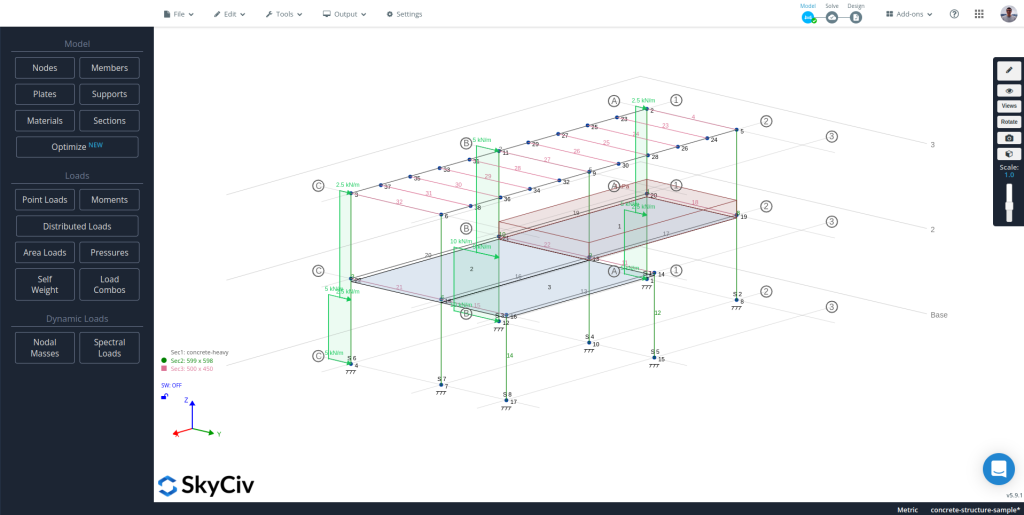
Defining gridlines and elevations when modeling a structure, especially a multi-story building, can help a lot to speed up the process. Using SkyCiv S3D, it is possible to define such gridlines and elevations and take full advantage of them.
Watch the video tutorial
Getting to the gridlines and elevations module
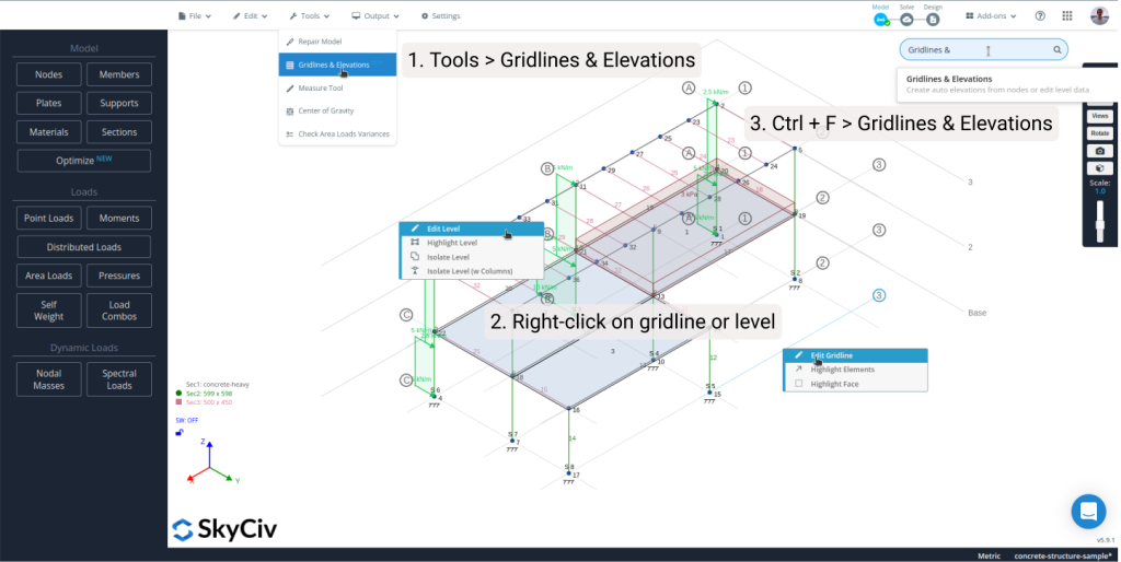
There are three different ways to get to the gridlines and elevations module:
- Using the top-bar: Navigate to “Tools” and click “Gridlines and Elevations”.
- Using the search bar: Hit Ctrl or Cmd + “F” and type “Gridlines & Elevations”, select the first option.
- Using the right-click menu: Right-click a level or a gridline of an existent model and click “Edit Level” or “Edit Gridline” accordingly.
Creating gridlines and elevations
There are two different workflows for getting elevations and gridlines in a model, one for new models and the other for existing ones.
Creating levels and gridlines for a new model
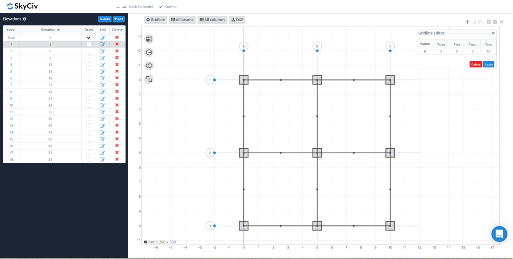
Once in the module, create the base level using the “Add” button in the top-right corner of the left-hand side panel, you will see the new level in the Elevations table and the graphical editor will be ready to edit. With the base level created, it is time to add all the gridlines there using the capabilities of the graphical editor (refer to the next section). From the table on the left-hand side panel, it is possible to:
- Modify the name of the level in the first column, it is the name that will appear on each level back in S3D
- Change the elevation of the level in the second column
- Set whether the level should be displayed or not in S3D in the third column
- Select the level to edit by clicking the icon on the fourth column, and
- Delete a level by clicking the “X” on the fifth column
It is important to mention that adding a new level will create an exact copy of the last level in the list, bringing all the gridlines, beams and columns associated with the last level.
Creating levels and gridlines for an existing model
For existing models, once in the module, click the “Auto” button located in the top-right of the left-hand side panel, a menu will show up right below the button to select which elements should use the software to detect levels and gridlines, after selecting the desired ones and clicking “Generate”, the software will analyze the model and look for the level as well as the gridlines based on the elements selected, once this finishes, you will see the newly created levels on the table in the left-hand side panel.
Note: Whenever the module is doing some work in the background, a spinner will show up in the top-right corner of the graphical editor, it should not block the UI, so you can keep working. It will disappear once the process is complete.
Using the graphical editor
Upon selecting a level to edit, using the graphical editor on the right, it is possible to create a new gridline for that specific level or edit an existing one, create all the possible beams and columns with the gridlines given, or edit/delete them, and upload a DXF file containing lines to be used as gridlines:
- Drawing a new gridline: Click the “Gridline” button on the buttons row on top of the plot and using the mouse click two points at the intersection of the base grids. The spacing between the base grid can be adjusted using the first button on the button column at the left of the plot.
- Modifying an existing gridline: To edit the start and end point of a gridline, click the point plotted at the intersection between the gridline and its bubble, and a small form will show up in the top-right corner of the plot with a table to edit the coordinates and the gridline label. To edit the bubble radius and distance between the bubbles, use the second and third buttons below the one for changing the base grid’s spacing.
- Creating beams and columns: Once the gridlines are properly defined, use the “All beams” and “All columns” buttons located at the top of the plot to create all the possible beams and columns using the intersections of the defined gridlines. To change the section ID assigned to the elements that the module will create, use the fourth button in the column on the left of the plot.
- Edit or erase existing beams and columns: Click the dot and the middle of the span for the case of beams, and the dot at the center of the section for the case of columns.
- Import a DXF containing the gridlines: Sometimes it is faster to draw lines using CAD software, use the fourth button at the top of the plot to upload a DXF file and import the gridlines from the lines defined in that file.
Note: As for now, the slowest part of the module is updating the plot with the gridlines, beams, and columns. Having a very small snap size will slow the rendering process a lot, so it is recommended to set a large snap size to make it faster.
Sending data back to S3D
After creating all the levels, and all the gridlines, columns, and beams for each level, click “Submit” and all that data will be synchronized with your S3D model. Come back to the module if you need to change something.
Interacting with levels and gridlines from S3D
For each level and gridlines drawn in S3D there are a couple of options that might help when right-clicking one of those elements:
For gridlines:
- Edit Gridline will open the gridlines and elevations module with that gridline selected and ready to edit
- Highlight Elements will select all the members and nodes that fall on that gridline
- Highlight Face will select all the members and nodes that fall on a vertical plane parallel to the gridline
For levels:
- Edit Level will open the gridlines and elevations module with that level selected and ready to edit in the graphical editor
- Highlight level will highlight all the elements in that level
- Isolate level will isolate all the members and nodes in that level. To show all, right-click anywhere on the canvas and select “Show All”
- Isolate level (w Columns) will isolate all the members and nodes in that level and the columns connected to it above or below. To show all, right-click anywhere on the canvas and select “Show All”