SkyCiv Foundation provides a user-friendly interface paired with a powerful design to easily model isolated foundations. In the recently released Version 3.1, the Isolated Foundation user interface is divided into 2 containers, the left containing 4 tabs which include Details, Foundations, Input and Results, and the right containing the 3D renderer.
I. Details
Once the user has chosen a design code, the user can update the project details on the “Details” tab as shown below. The units will be set automatically based on the design code chosen.
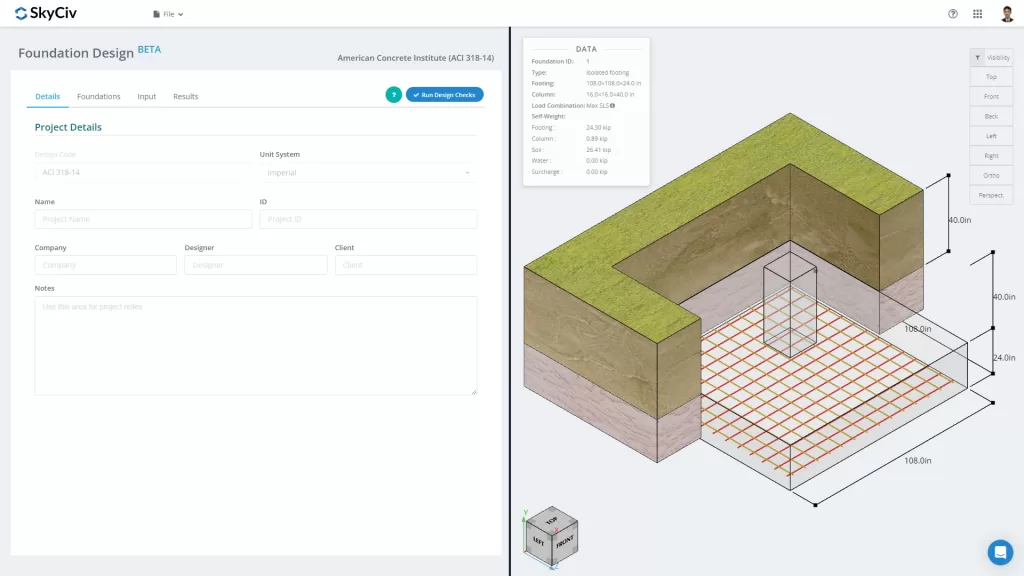
Figure 1. Project Details tab
The user can fill the information for the project details, such as
- A Project Name
- A Project ID
- Your Company Name
- The Designer
- The Client
- Project Notes (open ended notes)
All of the information will be inserted into the generated design report.
II. Foundations
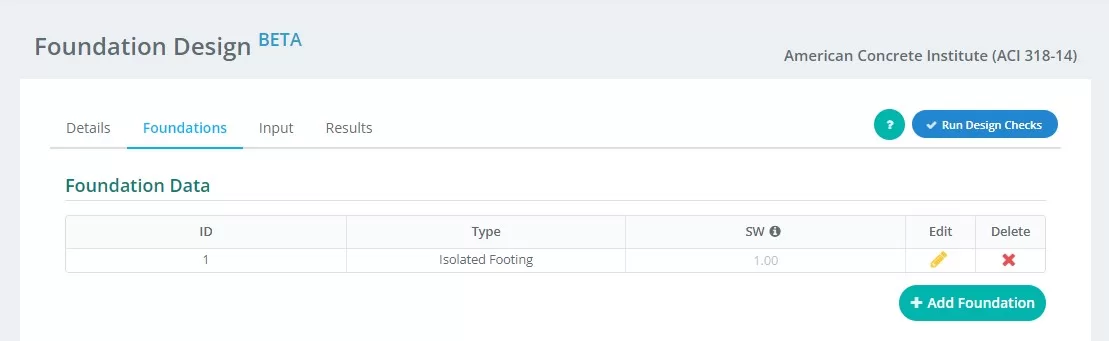
Figure 2. Foundation tab details
Summary of inputs on the “Foundation” tab:
- Foundation ID – assign numerical identification to each foundation.
- Type – select “Isolated Foundation” from the drop-down menu.
- SW – self-weight factor
- Edit – click this to start inputting data and edit your foundation
- Delete – to delete the foundation
III. Input
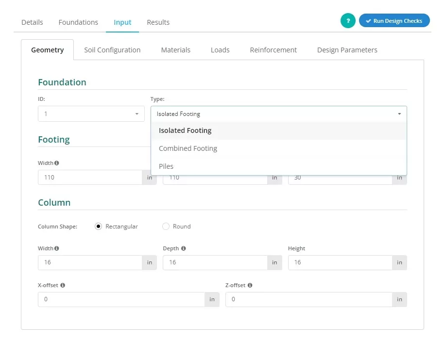
Figure 3. Selecting the Isolated Footing on the drop-down menu.
Users can establish the type of foundation as shown in Figure 3, select “Isolated Footing” to bring up this view.
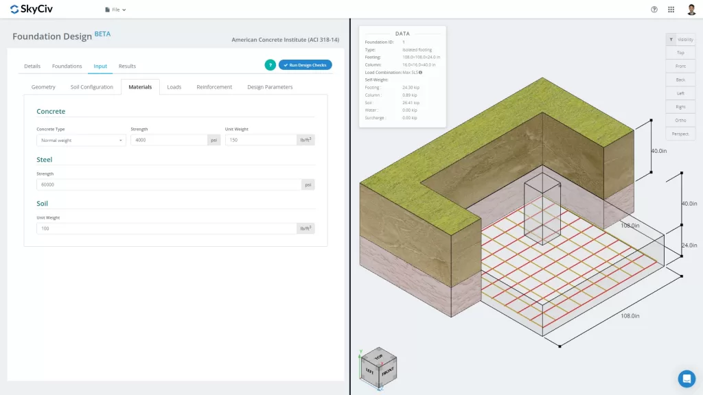
Figure 4. Foundation Tab
The “Input” tab separates input categories including Geometry, Soil Configuration, Materials, Loads, Reinforcement and Miscellaneous. These inputs will automatically update the 3D graphics on the right tab of the screen. The right container will be discussed in the last part of this documentation.
Let’s go over the different input categories in a little more detail:
Geometry
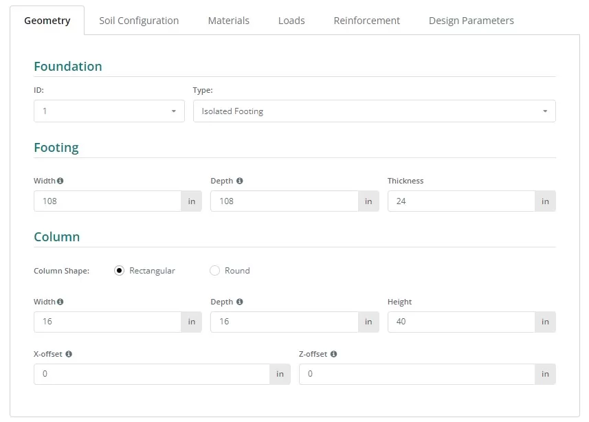
Figure 5. Geometry at the left tab.
See Figures 6 and 7 for the nomenclature of the foundation and column dimensions:
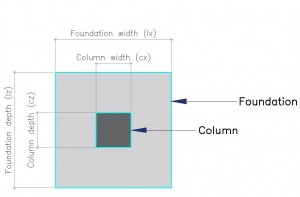
Figure 6. Foundation with designation
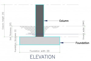
Figure 7. Elevation view of the Foundation
Soil Configuration
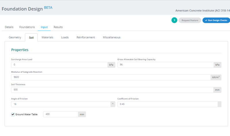
Figure 8. Soil Configuration at the left tab.
Note:
- Soil values are usually found in the Geotechnical Report.
- Tick the “Ground Water Table” box to define the groundwater height.
- The value for the modulus of subgrade reaction automatically updates when the value of ‘Gross Allowable Soil Bearing Capacity” is changed. However, users can still overwrite this value.
Materials
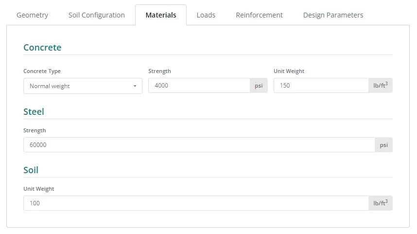
Figure 9. Materials button at the left tab.
Loads
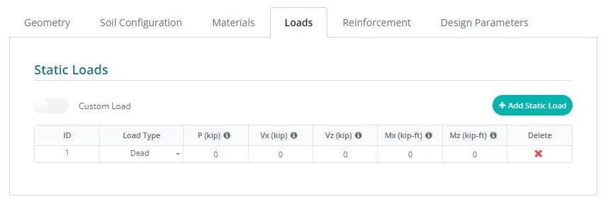
Figure 10. Loads button at the left tab.
Reinforcement
Typically, isolated footing includes bottom reinforcements only, though an option for top reinforcements can be accessed by clicking the corresponding button. Updating the reinforcements is easy, select the bar size on the dropdown list and input the necessary spacing.
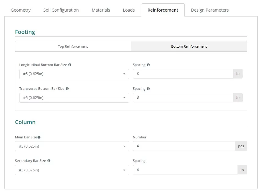
Figure 11. Reinforcement button at the left tab.
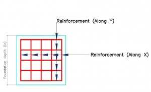
Figure 12. Details of Reinforcement.
Rebar Code Reference:
- ASTM615 – American Society for Testing and Materials 615 : Standard Specification for Deformed and Plain Carbon-Steel Bars for Concrete Reinforcement
- N – Australian Rebar Class N
- PNS49 – Philippines National Standard 49 : Steel bars for concrete reinforcement – Specification.
- E2 – Eurocode Rebar P
Miscellaneous
This tab contains other inputs necessary for the chosen design code. It also contains some input to control the mesh size of the finite element model and punching shear edge factor for punching shear check.
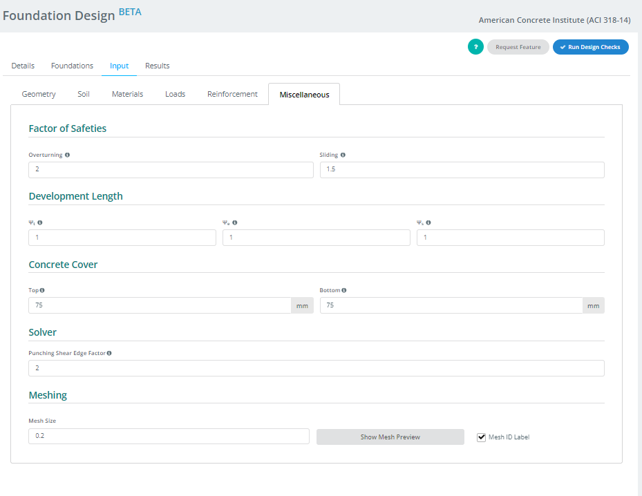
Figure 13. Miscellaneous button at the left tab.
IV. Results
Your design will produce the results table after clicking the Run Design Check button. Each column, except for the last two, represents a design check completed by the Foundation module. The values are utility ratios; anything equal to or under 1.0 is a PASS, and anything over 1.0 is a FAIL. The last two columns contain the color-coded status and the option to access or download the report in HTML or PDF formats.
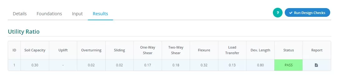
Figure 14. Results Output at the left tab.
Summary of column representations:
- Soil Pressure
Ratio of soil pressure from experienced loads over allowable soil pressure. - Uplift
Determines if uplift exists on the loading - Overturning
Ratio of overturning moment experienced over allowable overturning moment. - Sliding
Ratio of sliding force experienced over sliding resistance. - One-Way Shear
Ratio of ONE-way shear demand over capacity. - Two-Way Shear
Ratio of TWO-way shear demand over capacity. - Flexure
Ratio of flexural demand over flexural capacity. - Load Transfer
Ratio of nominal over actual bearing strength. - Development Length
Ratio of nominal over actual development length. - Status
Indicates that the foundation design is PASS or FAIL - Report
Click to see detailed calculation of the foundation design.
V. Renderer
Lastly, located at the right part of the screen is the 3D renderer to help users visualize the inputs. On the upper left corner is the model summary data containing basic information about the foundation, and on the opposite corner is the visibility settings. Users can select objects they want to show or hide and choose the orientation of the graphic they wish to see.
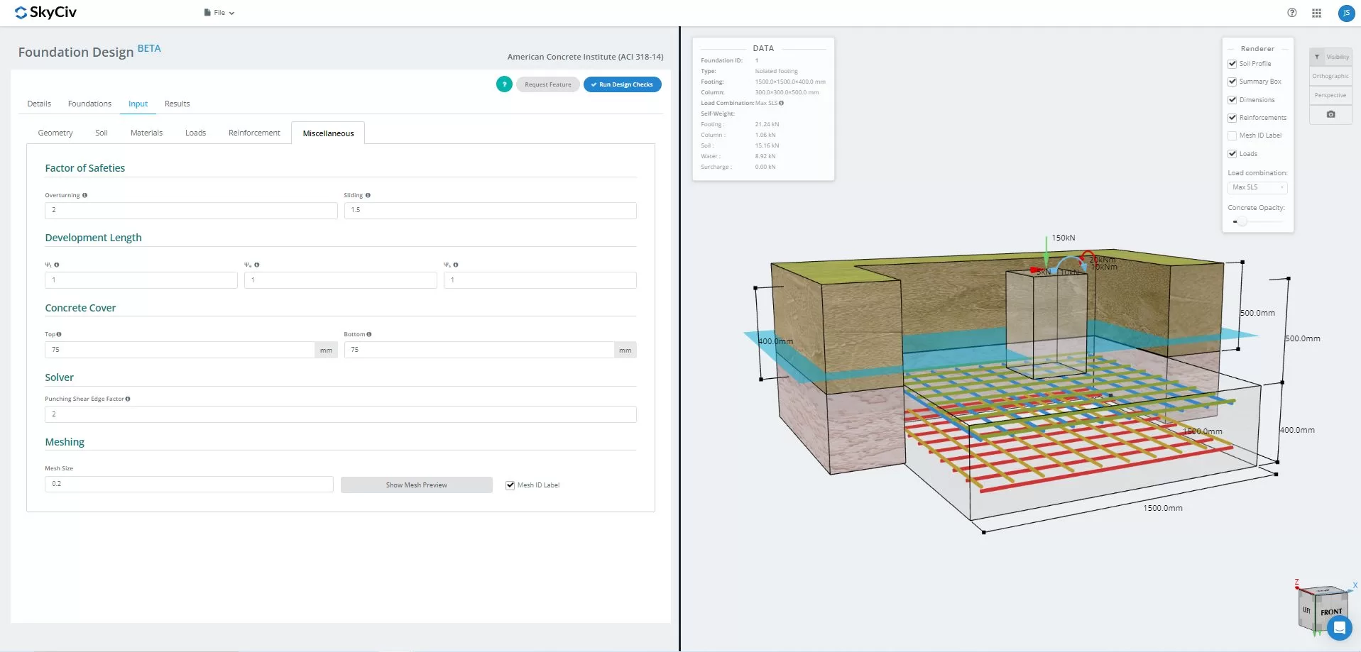
Figure 15.3D Graphical representation of the model
Once solved, users can view the FEA results soil pressure, and wood-armer analysis in 3D. Results can switched across all load combinations, including envelope cases. A screenshot of the current view can also be downloaded.
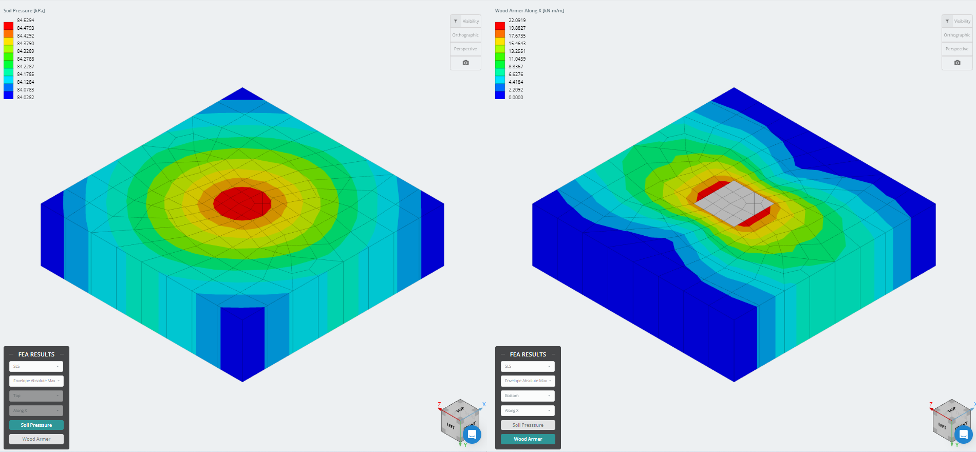
Figure 16. Finite Element Analysis Results
Want to try SkyCiv’s Foundation Design software? Our tool allows users to perform Foundation Design calculations without downloading or installing!
Reference:
- Building Code Requirements for Structural Concrete (ACI 318-14) Commentary on Building Code Requirements for Structural Concrete (ACI 318R-14). American Concrete Institute, 2014.
- Taylor, Andrew, et al. The Reinforced Concrete Design Handbook: a Companion to ACI-318-14. American Concrete Institute, 2015.