A fully worked example of Eurocode 1 (EN 1991-1-4) wind load calculations
In this example, we will be calculating the design wind pressure for a warehouse structure located in Aachen, Germany. Our references will be the Eurocode 1 EN 1991-1-4 Action on structures (wind load) and DIN EN 1991-1-4/NA:2010-12. We shall be using a model from our S3D to demonstrate how the loads are applied on each surface.
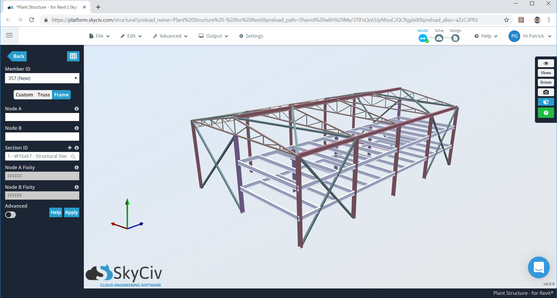
Figure 1. Warehouse model in SkyCiv S3D as example.
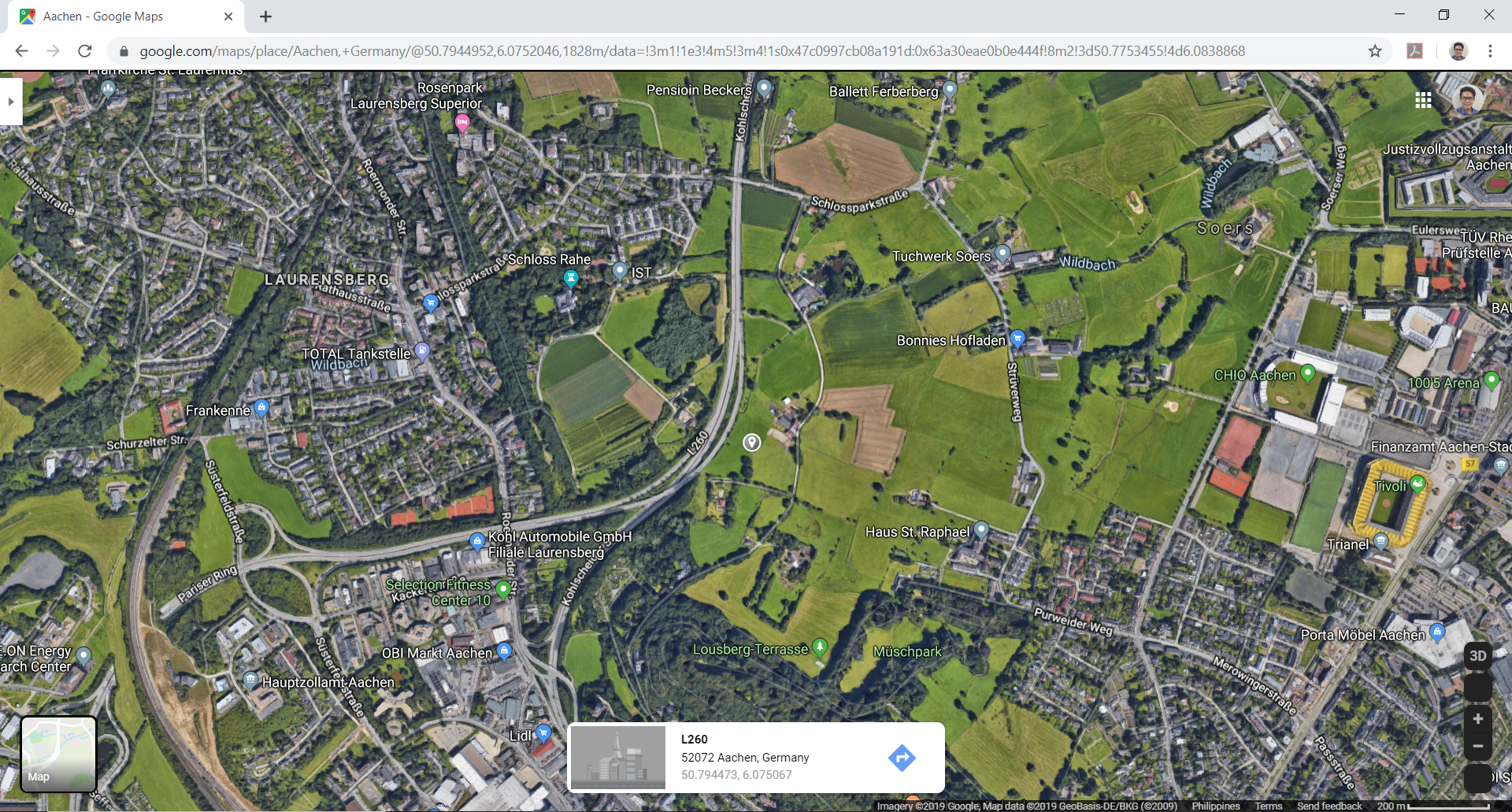
Figure 2. Site location (from Google Maps).
Table 1. Building data needed for our wind calculation.
| Location | Aachen, Germany |
|---|---|
| Occupancy | Miscellaneous – Warehouse Structure |
| Terrain | Flat farmland |
| Dimensions | 19.507 m (d) × 31.699 m (b) in plan Eave height of 9.144 m Apex height at elev. 10.973 m (h) Roof slope 3:16 (10.62°) Without opening |
| Cladding | Purlins spaced at 0.6 m Wall studs spaced at 0.6 m |
The formula in determining the design wind pressure are:
For basic wind velocity:
\({v}_{b} = {c}_{dir} {c}_{season} {v}_{b,0}\) (1)
Where:
\({v}_{b}\) = basic wind velocity in m/s
\({c}_{dir}\) = directional factor
\({c}_{season}\)= seasonal factor
\({v}_{b,0}\) = fundamental value of the basic wind velocity (DIN National Annex for EN 1991-1-4)
For basic velocity pressure:
\({q}_{b} = 0.5 {⍴}_{air} {{v}_{b}}^{2} \) (2)
Where:
\({q}_{b}\) = design wind pressure in Pa
\({⍴}_{air}\) = density of air (1.25 kg/cu.m.)
\({v}_{b}\)= basic wind velocity in m/s
For peak pressure:
\({q}_{p}(z) = 0.5 [1 + 7 {l}_{v}(z)] {⍴}_{air} {{v}_{m}(z)}^{2} \) (3)
Where:
\({v}_{m}(z)\) = mean wind velocity, m/s = \({c}_{r}(z) {c}_{o}(z) {v}_{b}\) (4)
\({c}_{o}(z)\) = topography factor
\({c}_{r}(z)\) = roughness factor:
\({c}_{r}(z) = {k}_{T} ln(\frac{z}{{z}_{0}}) : {z}_{min} ≤ {z} ≤ {z}_{max}\) (5)
\({c}_{r}(z) = {c}_{r}({z}_{min}) : {z} ≤ {z}_{min}\) (6)
Where:
\({z}_{0}\) = roughness length, m
\({k}_{T}\) = terrain factor, depending on the roughness length, \({z}_{0}\) calculated using:
\({k}_{T} = 0.19 {(\frac{{z}_{0}}{{z}_{0,II}})}^{0.07} \) : \( {z}_{0,II} = 0.05\) (terrain category II) (7)
\({z}_{min}\) = minimum height
\({z}_{max}\) = maximum height taken as 200 m.
From these Equations (4) to (7), DIN EN 1991-1-4/NA:2010-12 Annex B summarizes the formula for each parameter depending on the terrain category:
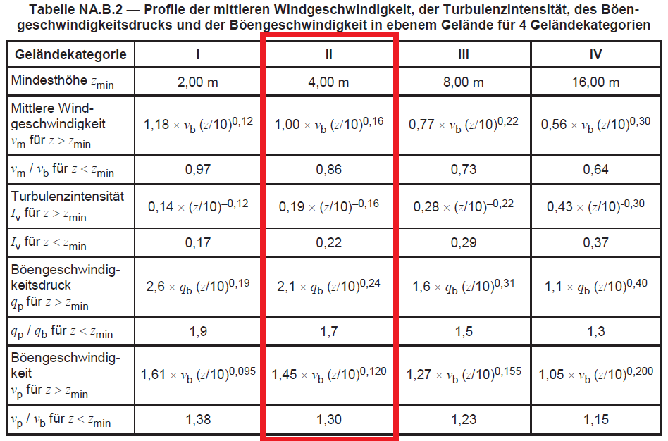
Figure 3. Table NA.B.2 of DIN EN 1991-1-4/NA:2010-12.
Each parameter will be discussed in subsequently.
Terrain Category
The structure is located on farmland, which is classified as Terrain Category II as defined in Annex A of EN 1991-1-4 and Table NA.B-1 of DIN National Annex.
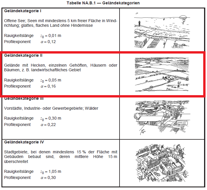
Figure 4. Table NA.B.1 of DIN EN 1991-1-4/NA:2010-12.
Directional and Seasonal Factors, \({c}_{dir}\) & \({c}_{season}\)
In order to calculate for Equation (1), we need to determine the directional and seasonal factors, \({c}_{dir}\) & \({c}_{season}\). DIN National Annex for EN 1991-1-4 simplifies this calculation as the suggested values of these factors are equal to 1.0.
Basic Wind Velocity and Pressure, \({v}_{b,0}\) & \({q}_{b,0}\)
As mentioned earlier, wind speed map for Germany can be taken from DIN National Annex for EN 1991-1-4. Each European country has a separate National Annex in which it calibrates the suggested wind load parameters of EN 1991-1-4.
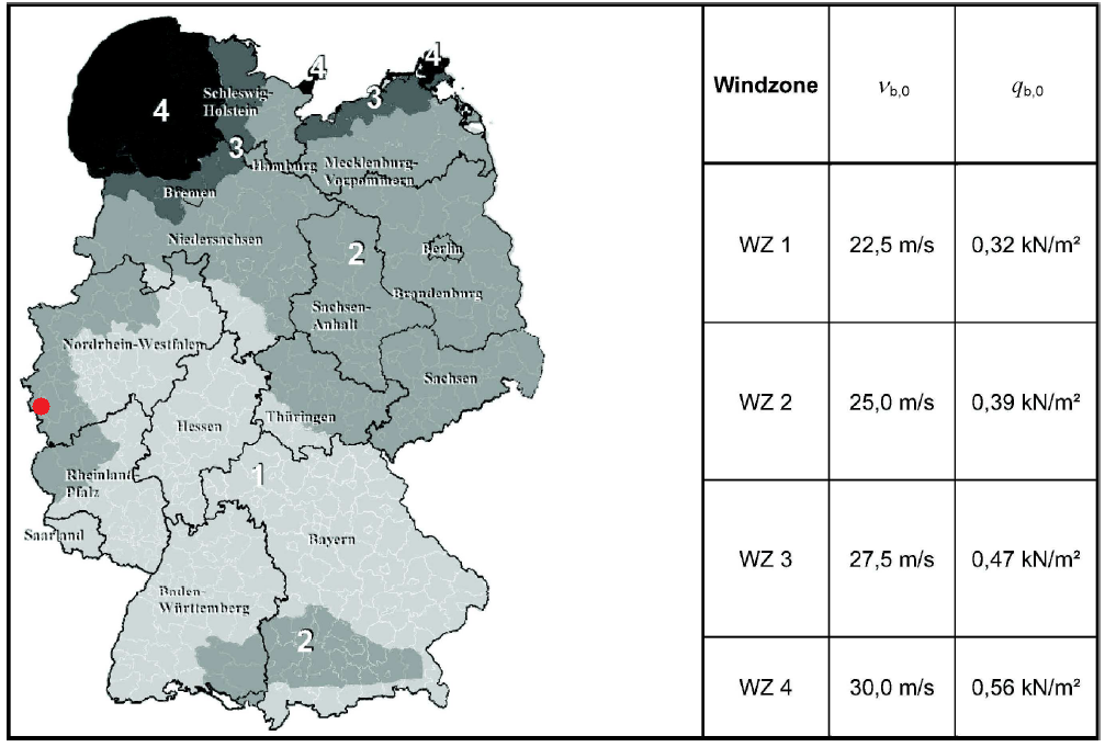
Figure 5. Table NA.A.1 of DIN EN 1991-1-4/NA:2010-12.
For our site location, Aachen, Germany is located in WZ2 with \({v}_{b,0}\) = 25.0 m/s as shown in figure above. From this value, since \({c}_{dir}\) & \({c}_{season}\) are both equal to 1.0, we can calculate the basic wind pressure, \({q}_{b,0}\), using Equations (1) and (2). Hence, the corresponding value of \({q}_{b,0}\) = 0.39 kPa, also indicated in the wind map of DIN National Annex for EN 1991-1-4.
SkyCiv now automates detection of wind region and getting the corresponding wind speed value with just a few input. Try our SkyCiv Free Wind Tool
Mean Wind Velocity, \({v}_{m}(z)\)
In order to calculate for the peak pressure, \({q}_{p}(z)\), we need to determine the value of mean wind velocity, \({v}_{m}(z) \). From Figure 3, we can calculate the mean velocity, \({v}_{m}(z) \):
For \({z}_{min} ≤ {z} ≤ {z}_{max} : 1.0 {v}_{b} {(0.1z)}^{0.16} \)
For \({z}_{min} ≤ {z} ≤ {z}_{max} : 0.86 {v}_{b} \)
Peak Pressure, \({q}_{p}(z)\)
Similarly, the peak pressure, \({q}_{p}(z)\), can be solved using Figure 3:
For \({z}_{min} ≤ {z} ≤ {z}_{max} : 2.1 {q}_{b} {(0.1z)}^{0.24} \)
For \({z} ≤ {z}_{min} : 1.7 {q}_{b} \)
In order to calculate for the peak pressure, \({q}_{p}(z) \), we need to determine the value of mean wind velocity, \({v}_{m}(z) \). From Figure 3, we can calculate the mean velocity, \({v}_{m}(z) \):
for \({z}_{min} ≤ {z} ≤ {z}_{max} : 1.0 {v}_{b} {(0.1z)}^{0.16} \)
for \({z} ≤ {z}_{min} : 0.86 {v}_{b} \)
Results for mean wind velocity and peak pressure for each level are show in Table 2 below.
Table 2. Calculated mean wind velocity and peak pressure for each level of the structure.
| height/level | \({v}_{m}(z)\), m/s | \({q}_{p}(z)\), Pa |
|---|---|---|
| 3.00 | 21.5 | 664.06 |
| 6.00 | 23.04 | 725.66 |
| 9.00 | 24.58 | 799.83 |
| 10.97 (h) | 25.37 | 838.80 |
External Wind Pressure, \({w}_{e}\)
Upon calculation of peak pressure, \({q}_{p}(z)\), the external wind pressure acting on the surface of the structure can be solved using:
\({w}_{e} = {q}_{p}(z) {c}_{pe}\) (8)
Where:
\({w}_{e}\) = external wind pressure, Pa
\({q}_{p}(z)\) = peak pressure, Pa
\({c}_{pe}\) = pressure coefficient for external surface
a) Vertical Walls
For distribution of windward pressure (Zone D), Section 7.2.2 of EN 1991-1-4 describes the how it should be distributed depending on \(h\), \(b\), and \(d\). For our example, we have \(h < b\) (10.973 < 31.699m), hence, \({z}_{e} = h\) as shown in Figure 6.
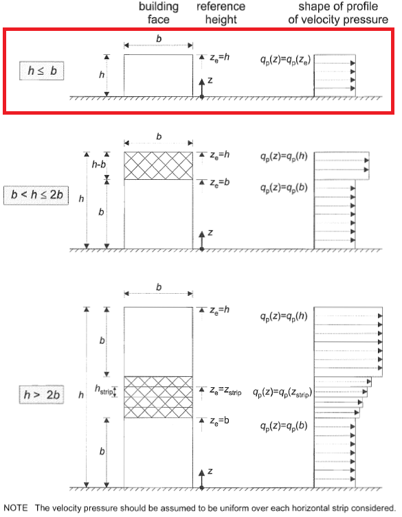
Figure 6. Pressure distribution for windward wall based on Figure 7.4 of EN 1991-1-4.
On the other hand, pressure distribution for sidewalls (Zones A to C) are shown in Figure 7.5 of EN 1991-1-4 and depends on the \(e = b < 2h\). For our example, the value of \(e = 21.946\), hence, \(e > d\) as shown in Figure 7. Moreover, leeward wall pressure is designated as Zone E. External pressure coefficients are then indicated in Figure 8 based on Table NA.1 of DIN EN 1991-1-4/NA:2010-12.
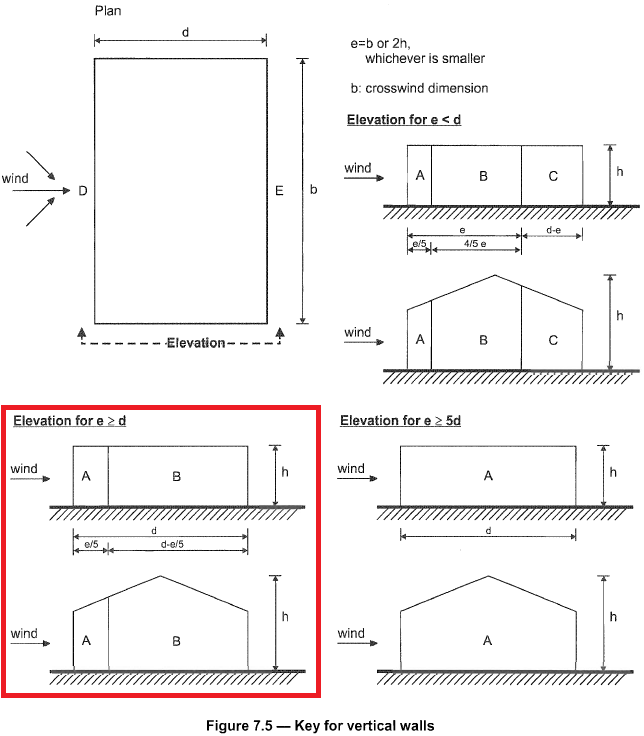
Figure 7. Pressure distribution for sidewall based on Figure 7.5 of EN 1991-1-4.
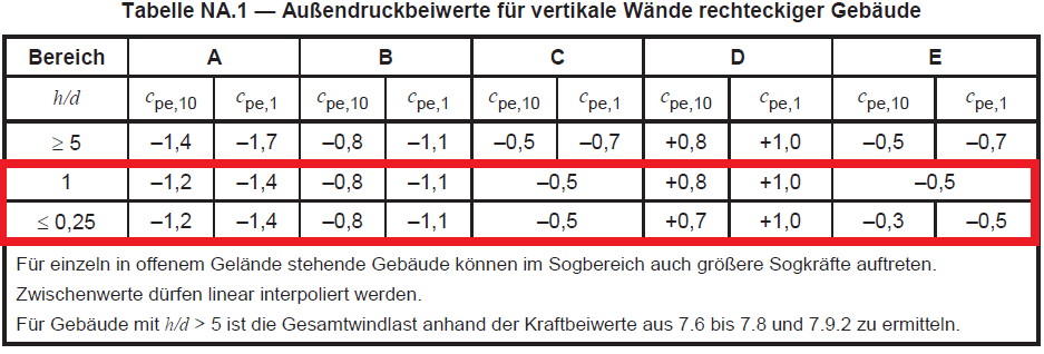
Figure 8. External pressure coefficient for vertical walls (Zones A to E) based on Table NA.1 of DIN EN 1991-1-4/NA:2010-12.
Since \(h/d = 0.563\), we will need to interpolate the \({c}_{pe}\) values in order to calculate for the design wind pressure. The subscripts for \({c}_{pe,10}\) and \({c}_{pe,1}\) mean that the value is dependent on the area where the wind pressure is applied, for either 1 sq.m. and 10 sq.m. Usually, for buildings, \({c}_{pe,10}\) is the one to be adopted since \({c}_{pe,1}\) is used for small elements such as claddings and roofing elements. The interpolated values for \({c}_{pe}\) are shown in Table 3 below.
Table 3. Calculated external pressure coefficient for vertical walls.
| \(h/d\) | A | B | C | D | E |
|---|---|---|---|---|---|
| 1.000 | -1.2 | -0.8 | -0.5 | 0.8 | -0.5 |
| 0.563 | -1.2 | -0.8 | -0.5 | 0.742 | -0.383 |
| 0.250 | -1.2 | -0.8 | -0.5 | 0.7 | -0.3 |
b) Roof
Distribution of design wind pressures for roof are detailed in Sections 7.2.3 to 7.2.10 and 7.3 of EN 1991-1-4. Specifically, since the roof profile of our structure is duopitch, we will be using Section 7.2.5 to get the roof external pressure coefficients, \({c}_{pe}\), as shown in Figure 9 and 10 below.
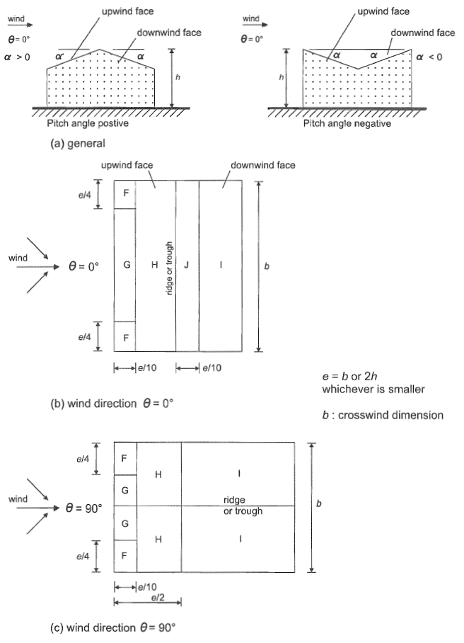
Figure 9. Pressure distribution for duopitch roof based on Figure 7.8 of EN 1991-1-4.
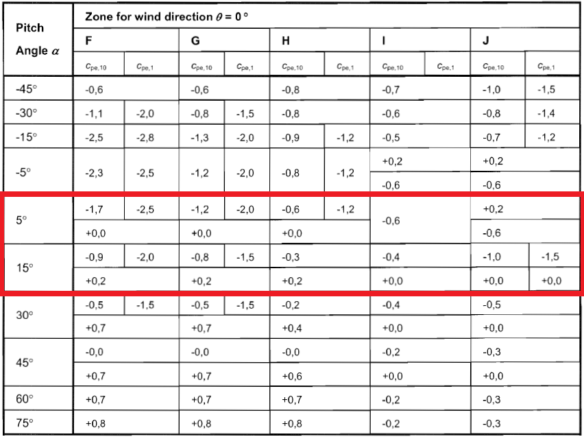
Figure 9. External pressure coefficient for roof surfaces walls (Zones F to J) based on Table 7.4a of EN 1991-1-4.
Since the roof pitch angle is equal to 10.62°, we need to interpolate the \({c}_{pe}\) values of 5° and 15°. Hence, the calculated \({c}_{pe}\) values for our structure is shown in Table 4 below.
Table 4. Calculated external pressure coefficient for roof surfaces.
| \(h/d\) | Zone F | Zone G | Zone H | Zone I | Zone J | |||||
|---|---|---|---|---|---|---|---|---|---|---|
| \(-{c}_{the}\) | \(+{c}_{the}\) | \(-{c}_{the}\) | \(+{c}_{the}\) | \(-{c}_{the}\) | \(+{c}_{the}\) | \(-{c}_{the}\) | \(+{c}_{the}\) | \(-{c}_{the}\) | \(+{c}_{the}\) | |
| 5.00 | -1.7 | 0.0 | -1.2 | 0.0 | -0.6 | 0.0 | -0.6 | – | -0.6 | 0.2 |
| 10.62 | -1.250 | 0.112 | -0.975 | 0.112 | -0.431 | 0.112 | -0.488 | – | -0.825 | 0.088 |
| 15.00 | -0.9 | 0.2 | -0.8 | 0.2 | -0.3 | 0.2 | -0.4 | – | -1.0 | 0.0 |
Internal Wind Pressure, \({w}_{i}\)
Internal wind pressure, \({w}_{i}\), can develop and will act simultaneously with the external wind pressure. Hence, the need to calculate \({w}_{i}\) is necessary. The formula to calculate \({w}_{i}\) is:
\({w}_{i} = {q}_{p}(z) {c}_{pi}\) (9)
Where:
\({w}_{i}\) = internal wind pressure, Pa
\({q}_{p}(z)\) = peak pressure, Pa
\({c}_{pi}\) = internal pressure coefficient
Section 7.2.9 of EN 1991-1-4 states that \({c}_{pi}\) can be taken as the more onerous of +0.2 and -0.3. We assume that our structure has no dominant opening.
Design Wind Pressure
With these \({c}_{pe}\) and \({c}_{pi}\) values, we can now calculate the corresponding external wind pressure for each zone as shown in Table 5.
Table 5. Calculated external wind pressure each surface.
| Surface | Zone | \({w}_{e}\) | \({w}_{i}\) | Combined \({w}_{e}\) and \({w}_{i}\) | |||
|---|---|---|---|---|---|---|---|
| \(-{c}_{pe}\) | \(+{c}_{pe}\) | \(+{c}_{pi}\) | \(+{c}_{pi}\) | min value | max value | ||
| Wall | Zone A | -1006.56 | 167.76 | -251.64 | -1174.32 | 754.92 | |
| Zone B | -671.04 | – | -838.80 | -419.40 | |||
| Zone C | -419.40 | – | -587.16 | 167.76 | |||
| Zone D | – | 622.11 | 454.35 | 873.75 | |||
| Zone E | -321.54 | – | -489.30 | -69.9 | |||
| Roof | Zone F | -1048.83 | 94.28 | -1216.59 | 345.92 | ||
| Zone G | -818.00 | 94.28 | -985.76 | 345.92 | |||
| Zone H | -361.86 | 94.28 | -529.62 | 345.92 | |||
| Zone I | -409.00 | -576.76 | -157.36 | ||||
| Zone J | -691.84 | 73.48 | -859.60 | 325.12 | |||
From these values, we can now apply these design wind pressures to our structure. Considering one frame bay (inner), the combined \({w}_{e}\) and \({w}_{i}\) is as follows:
Figure 10. Inner frame to be considered.
Figure 11. Minimum case for combined \({w}_{e}\) and \({w}_{i}\).
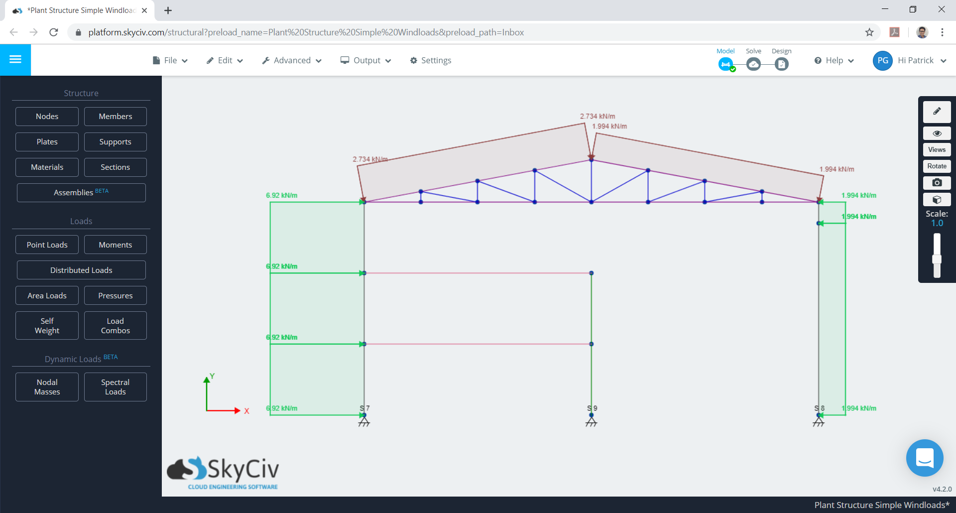
Figure 12. Maximum case for combined \({w}_{e}\) and \({w}_{i}\).
These calculations can be all be performed using SkyCiv’s Wind Load Software for ASCE 7-10, 7-16, EN 1991, NBBC 2015 and AS 1170. Users can enter in a site location to get wind speeds and topography factors, enter in building parameters and generate the wind pressures. With a Professional Account, users can auto apply this to a structural model and run structural analysis all in the one software.
Otherwise, try our SkyCiv Free Wind Tool for wind speed and wind pressure calculations on simple structures.

Structural Engineer, Product Development
MS Civil Engineering
References:
- En, B. (2005). Eurocode 1: Actions on Structures—Part 1–4: General Actions—Wind Actions.
- DIN EN 1991‐1‐4. (2005). Eurocode 1: Einwirkungen auf Tragwerke Teil 1‐4: Allgemeine Einwirkungen, Windlasten; Deutsche Fassung EN 1991‐1‐4: 2005.