A fully worked example of IS 875-3 wind load calculations
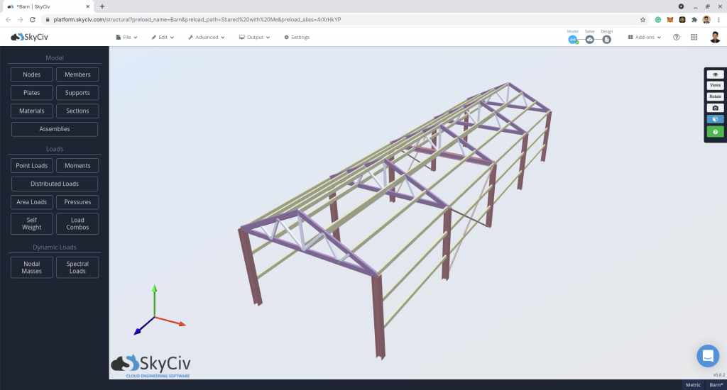
In this article, an example wind load pressure calculation for a building in Walwane, Maharashtra, India (18.945695° N, 74.564866° E) will be shown. This calculation will be in accordance with IS 875-3:2015 wind load calculations. SkyCiv free wind load calculator recently added the IS 875-3 wind load calculations, hence, we are going to demonstrate how to calculate the wind loads, by using an S3D Barnhouse model below:
For this case study, the structure data are as follows:
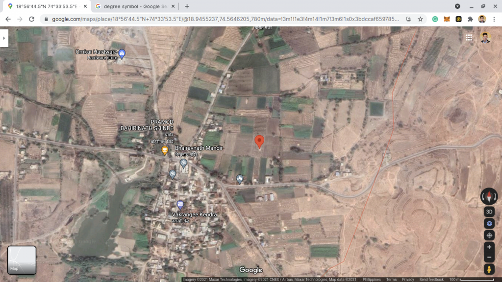
| Location | Walwane, Maharashtra, India (18.945695° N, 74.564866° E) |
| Occupancy | Miscellaneous – Farm structure |
| Terrain | Flat open land |
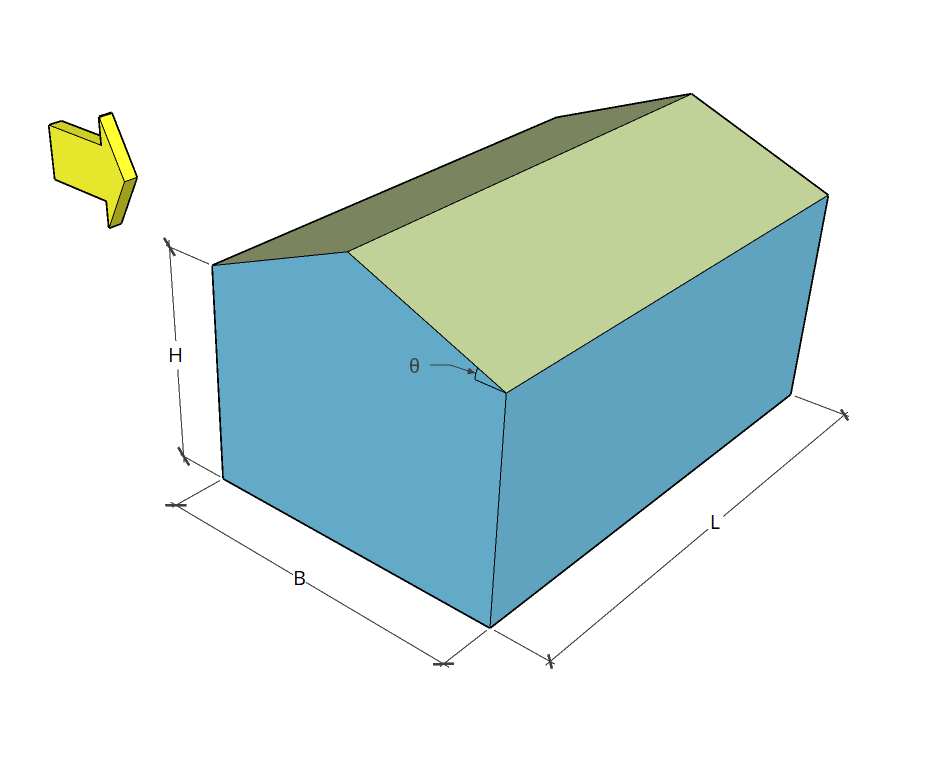
| Dimensions | B = 4 m × L = 14 m in plan H = Eave height of 2.4 m Apex height at elev. 3.4 m Roof slope 1:2 (26.565°) No opening |
| Cladding | Purlins spaced at 0.745m Wall studs spaced at 0.8m |
Using the IS 875-3: 2015, the design wind speed for the location and the design wind pressure for the rectangular building with pitched roof can be solved using the equations below:
Design wind speed at height z (in m/s): Vz = Vbk1k2k3k4 (1)
Where:
Vb is theBasic wind speed, m/s
k1 is the Probability factor (risk coefficient) based on 6.3.1 of IS 875-3
k2 is the Terrain roughness and height factor based on 6.3.2 of IS 875-3
k3 is the Topography factor based on 6.3.3 of IS 875-3
k4 is the Importance factor for the cyclonic region based on 6.3.4 of IS 875-3
Design wind pressure (in Pa): pd = KdKaKcpz (2)
Where:
Kd is the Wind directionality factor based on 7.2.1 of IS 875-3. Equal to 1.0 when considering local pressure coefficients.
Ka is the Area averaging factor based on 7.2.2 of IS 875-3
Kc is the Combination factor based on 7.3.3.13 IS 875-3
pz is equal to 0.60Vz2 in Pa
Note that pd should not be taken less than 0.70pz
From the design pressure pd obtained, the pressure will be distributed to the members of the by using:
Wind force on surface or members (in N): F = (Cpe – Cpi)Apd (3)
Where:
A is the surface area of the structural element or cladding unit
Cpe is the external pressure coefficients
Cpi is the internal pressure coefficients
We will dive deep into the details of each parameter below.
Basic Wind Speed Vb
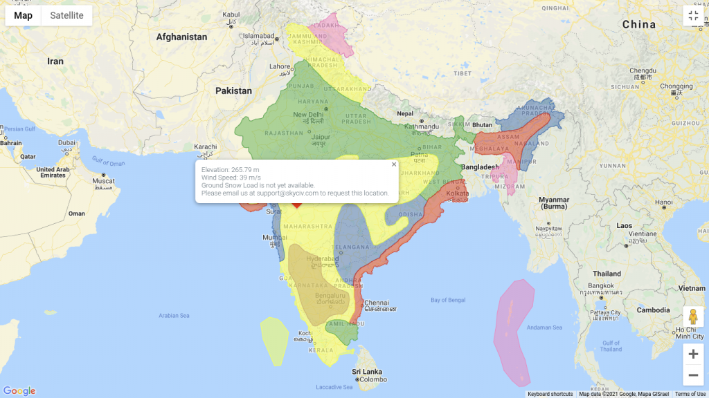
From Figure 1 of IS 875-3, the site location is situation of the map where the basic wind speed Vb is equal to 39 m/s.
SkyCiv can automate the wind speed calculations just defining the site location in India. Try our SkyCiv Free Wind Tool.
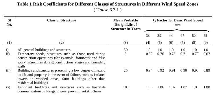
Probability Factor (Risk Coefficient) k1
Table 1 of IS 875-3 presents the risk coefficients for different classes of structures in different wind speed zones. For this structure, since it is a barnhouse and will be used to shelter some livestock animals, the structure is classified under “Buildings and structures presenting a low degree of hazard to life and property in the event of failure, such as isolated towers in wooded areas, farm buildings other than residential buildings.” Hence, from Table 1 of IS 875-3, the corresponding probability factor (risk coefficient) k1 is equal to 0.92.
Terrain Roughness and Height Factor k2
For this structure, it is located at the center of a farm where there are no immediate obstructions. Hence, the terrain can be classified as Category 1. Using Table 2 of IS 875-3:2015, we can obtain k2 values (which varies depending on the height being considered):
| Height | k2 |
| Reference height, H = 2.4 m | 1.05 |
Topography Factor k3
In order to account for topographic effects, we need to get the elevation data of the location for the eight (8) cardinal directions – N, S, W, E, NW, NE, SW, and SE – using Google elevation API. Based on the data, we can generally assume that the terrain is “Flat” for all directions. Hence, based on 6.3.3 of IS 875-3:2015, we can set our k3 equal to 1.0.
Importance Factor k4
Since the site location is not located within the east coast of India and the structure will only be used for agricultural purposes, the value of k4 is equal to 1.0 based on 6.3.4 of IS 875-3:2015
Design Wind Speed Vz
From the factors above, we can already solve the design wind speed Vz using Equation (1):
| Level | Vb m/s | k1 | k2 | k3 | k4 | Vz m/s |
| H = 2.4 m | 39.0 | 0.92 | 1.05 | 1.0 | 1.0 | 37.674 |
From the design wind speed, we can calculate the design wind pressure pd.
Wind Directionality Factor Kd
From 7.2.1 of IS 875-3:2015, the Wind Directionality Factor Kd is equal to 0.9 for frames and when considering local pressure coefficients, will be equal to 1.0. For this example, we will use Kd equal to 1.0 for purlins and wall studies and for Kd equal to 0.9 for the columns and trusses.
Area Averaging Factor Ka
The Area Averaging Factor Ka can be calculated using Table 4 of IS 875-3:2015:
Ka = 1.0 for area less than or equal to 10 sq.m.
Ka = 0.9 for area equal to 25 sq.m.
Ka = 0.8 for area greater than or equal to 100 sq.m.
Note that Ka can be linearly interpolated between values. For this structure, we need to get the tributary areas of columns for windward (Zone A), leeward (Zone B), sidewalls (Zone C and D), and truss for the roof. Moreover, we will also consider the tributary area of the wall studs and purlins.
| Component | Area, sq.m. | Ka |
| Column | 2.4×3.5 m = 8.4 sq.m. | 1.0 |
| Truss | 4×3.5 m (projection) = 14 sq.m. | 0.97 |
| Wall studs | 0.8×3.5 m = 2.8 sq.m. | 1.0 |
| Purlins | 0.745×3.5 m = 2.608 sq.m. | 1.0 |
Combination factor Kc
Since we will considered the simultaneous action of wall and roof pressures and internal pressures, the assumed Combination factor Kc is equal to 0.9 as referenced in 7.3.3.13 of IS 875-3:2015.
Design Wind Pressure, pd
Using Equation (2), we can calculate the design wind pressure, pd, Note that pz = 851.598 Pa and pd should not be less than 0.7pz or 596.119Pa.
| Component | Ka | Kd | Kc | pz | pd |
| Column | 1.0 | 1.0 | 0.9 | 851.598 | 766.438 |
| Truss | 0.97 | 1.0 | 0.9 | 851.598 | 743.445 |
| Wall studs | 1.0 | 1.0 | 0.9 | 851.598 | 766.438 |
| Purlins | 1.0 | 1.0 | 0.9 | 851.598 | 766.438 |
From these data, we need to calculate the pressure coefficients in order to distribute the design pressure to the components.
Internal Pressure Coefficients Cpi
The internal pressure coefficients Cpi can be determined from 7.3.2 of IS 875-3:2015. For this structure, it is assumed the total opening on the wall is less than 5 percent of the total wall area. Therefore, the Cpi values for this example are +0.2 and -0.2.
External Pressure Coefficients Cpe
The External Pressure Coefficients Cpe depend on certain parameters such as height, width, length, roof angle, and roof profile.
Wall External Pressure Coefficients
The external pressure coefficients for walls depend on h/w and l/w ratio, where h is the eave height, w is the least dimension of the building, and l is the larger dimension of the building. For this example, h = H, l = L, and w = B. Therefore, h/w = 0.6 and l/w = 3.5. From Table 5 of IS 875-3:2015, the corresponding Cpe values are as follows:
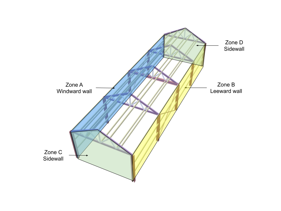
For wind angle = 0 degrees:
| Zone/Surface | Cpe |
| Zone A – Windward wall | +0.7 |
| Zone B – Leeward wall | -0.3 |
| Zone C – Sidewall | -0.7 |
| Zone D – Sidewall | -0.7 |
| Local zone (0.25w from edge) | -1.1 |
For wind angle = 90 degrees:
| Zone/Surface | Cpe |
| Zone A – Windward wall | -0.5 |
| Zone B – Leeward wall | -0.5 |
| Zone C – Sidewall | +0.7 |
| Zone D – Sidewall | -0.1 |
| Local zone (0.25w from edge) | -1.1 |
Note that w = 4 m.
Roof External Pressure Coefficients
For this structure, since the roof profile is gable or duopitch, the roof external pressure coefficients will be calculated based on Table 6 of IS 875-3:2015. For this example since h/w = 0.6, and the roof angle is 26.565°, the Cpe values will be interpolated using the following values:
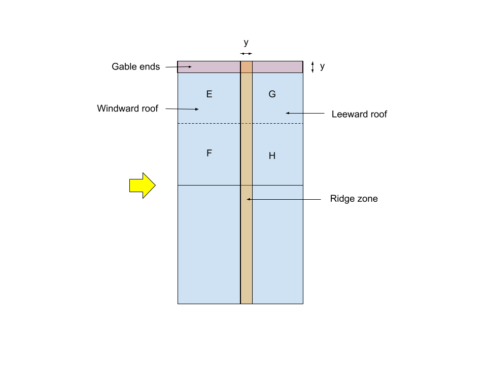
Note: y = 0.15w = 0.6m
For wind angle = 0 degrees:
| Roof angle | Zone EF – Windward | Zone GH – Leeward |
| 20° | -0.7 | -0.5 |
| 26.565° | -0.109 | -0.5 |
| 30° | -0.2 | -0.5 |
For wind angle = 90 degrees:
| Roof angle | Zone EG – Crosswind | Zone FH – Crosswind |
| 20° | -0.8 | -0.6 |
| 26.565° | -0.8 | -0.6 |
| 30° | -0.8 | -0.6 |
For local pressures:
| Roof angle | Gable ends | Ridge zones |
| 20° | -1.5 | -1.0 |
| 26.565° | -1.172 | -1.0 |
| 30° | -1.0 | -1.0 |
The final roof pressure coefficients will be:
| Zone/Surface | Wind direction – 0 degrees | Wind direction – 90 degrees |
| Zone EF – Windward | -0.109 | – |
| Zone GH – Leeward | -0.5 | – |
| Zone EG – Crosswind | – | -0.8 |
| Zone FH – Crosswind | – | -0.6 |
| Gable ends | -1.172 | -1.172 |
| Ridge zones | -1.0 | -1.0 |
Combined internal and external pressures
From the values above, the wind force can be calculated using Equation (3). However, for simplicity, we will just be getting the design pressure (not multiplying the values to the area A) and also will be considering the wind direction angle 0 degrees for the main frame (column and truss). The frame spacing is equal to 3.5m. Note that pd = 766.438 Pa for both column and wall studs.
For columns and wall studs – 0 degrees:
| Zone/Surface | Cpe | Cpi | Cpe–Cpi | p = pd(Cpe-Cpi) Pa | For Column px3.5m N/m | For wall studs px0.8m N/m |
| Zone A – Windward wall | 0.7 | +0.2 -0.2 | +0.5 +0.9 | 383.219 689.795 | 1341.267 2414.281 | 306.575 551.836 |
| Zone B – Leeward wall | -0.3 | +0.2 -0.2 | -0.5 -0.1 | -383.219 -76.644 | -1341.267 -268.253 | -306.575 -61.315 |
| Local zone (1m from edge) | -1.1 | +0.2 -0.2 | -1.3 -0.9 | -996.370 -689.795 | -3487.295 -2414.281 | -797.096 -551.836 |
The pressures on the columns will be multiplied to 3.5m in order to get a uniform load. Moreover, for the wall studs, it will be multiplied with 0.8m. Note that a positive pressure means it is acting towards the surface and negative is acting away from the surface (suction).
For truss and purlins – 0 degress:
| Zone/Surface | Cpe | Cpi | Cpe–Cpi | p = pd(Cpe-Cpi) Pa | Truss px3.5m N/m | Purlins px0.745m N/m |
| Zone EF – Windward | -0.109 | +0.2 -0.2 | -0.309 +0.091 | -229.725 67.654 | -804.036 236.787 | -171.145 50.402 |
| Zone GH – Leeward | -0.5 | +0.2 -0.2 | -0.7 -0.3 | -520.412 -223.034 | -1821.441 -780.617 | -387.707 -166.160 |
| Gable ends | -1.172 | +0.2 -0.2 | -1.372 -0.972 | -1051.553 -744.978 | -3680.437 -2607.423 | – |
| Ridge zones | -1.0 | +0.2 -0.2 | -1.2 -0.8 | -919.726 -613.151 | -3219.041 -2146.027 | – |
The pressures on the truss will be multiplied to 3.5m in order to get a uniform load. Moreover, for the wall studs, it will be multiplied with 0.745m. Note that pd = 766.438 Pa for the purlins and pd = 743.445 Pa for the truss.
Considering one critical frame – spacing is 3.5m:
For pd(Cpe – +Cpi):
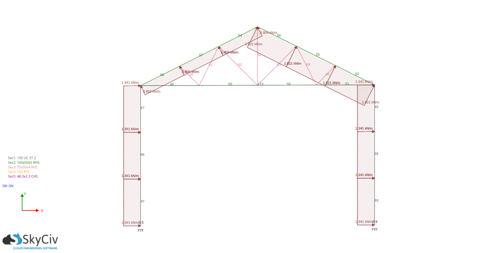
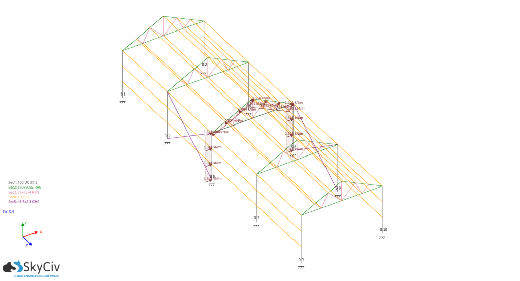
For pd(Cpe – -Cpi):
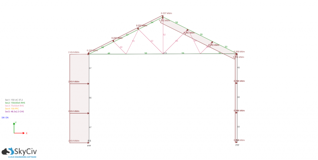
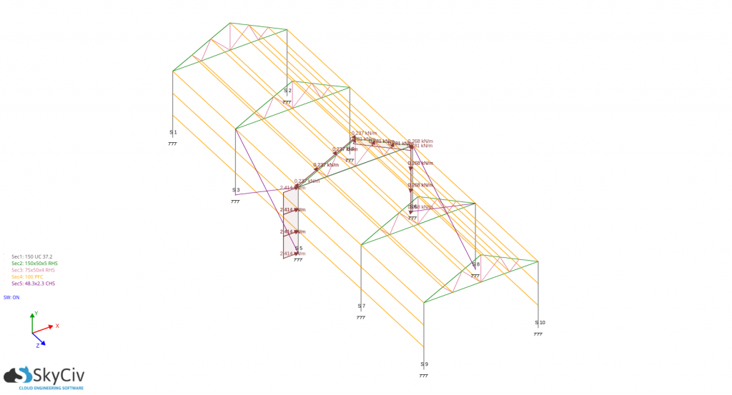
For the design of wall studs and purlins, you just need to get the absolute maximum pressure acting on it and use it as the basis in calculating the design forces. For this case, the design wind load are: -797.096 N/m for wall stud and -783.407N/m for the purlins,
These calculations can be all be performed using SkyCiv’s Load Generator Software for IS 875-3 and other codes as well. Users can enter in a site location to get wind speeds and topography factors, enter in building parameters and generate the wind pressures. Try our SkyCiv Free Wind Tool for wind speed and wind pressure calculations on gable structures.

Structural Engineer, Product Development
MS Civil Engineering
References:
- Design Loads (Other than Earthquake) for Buildings and Structures — Code of Practice (Part 3 Wind Loads ed.). (2015). Bureau of Indian Standards.