SkyCiv Load Generator has recently added seismic load calculation in accordance with ASCE7-16. This involves integrating the USGS Seismic Data and processing it to generate the seismic base shear using Section 12.8 Equivalent Lateral Procedure. In this article, we will dive deeper into the process of calculating the seismic loads for a building using ASCE 7-16.
SkyCiv now integrated the site seismic data from USGS Web API. Try our SkyCiv Load Generator!
Structure Data
In this example, we will use the following data in calculating the seismic load:
Table 1. Building data needed for our seismic load calculation.
| Location | 8050 SW Beaverton Hillsdale Hwy, Portland, OR 97225, USA |
| Occupancy | Residential Building |
| Dimensions | 64 ft (4 bays) × 104 ft (6 bays) in plan Floor height 15 ft Roof height at elev. 75 ft Flat roof Column: 20″x20″ Beam: 14″x20″ Slab: 8″ thickness |
| Loading | Concrete unit weight : 156 pcf Superimposed dead load (on floor): 100 psf Superimposed dead load (on roof): 50 psf |
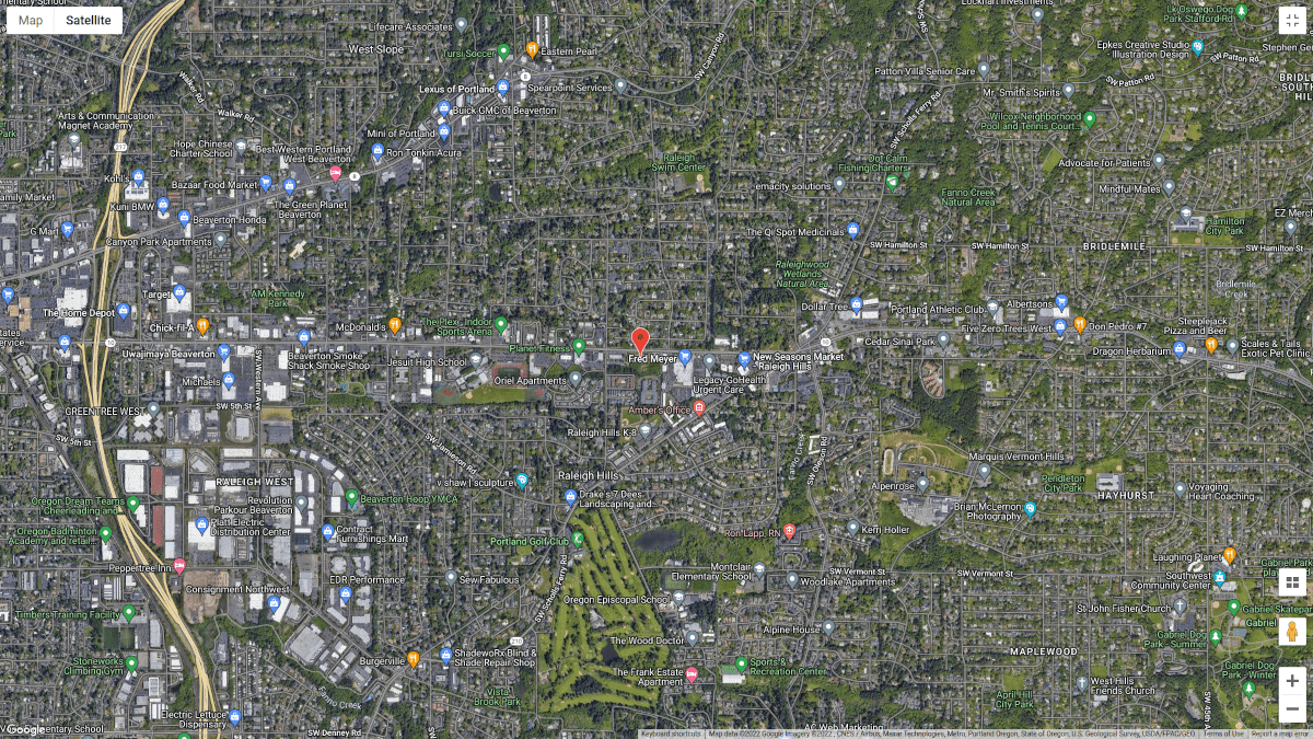
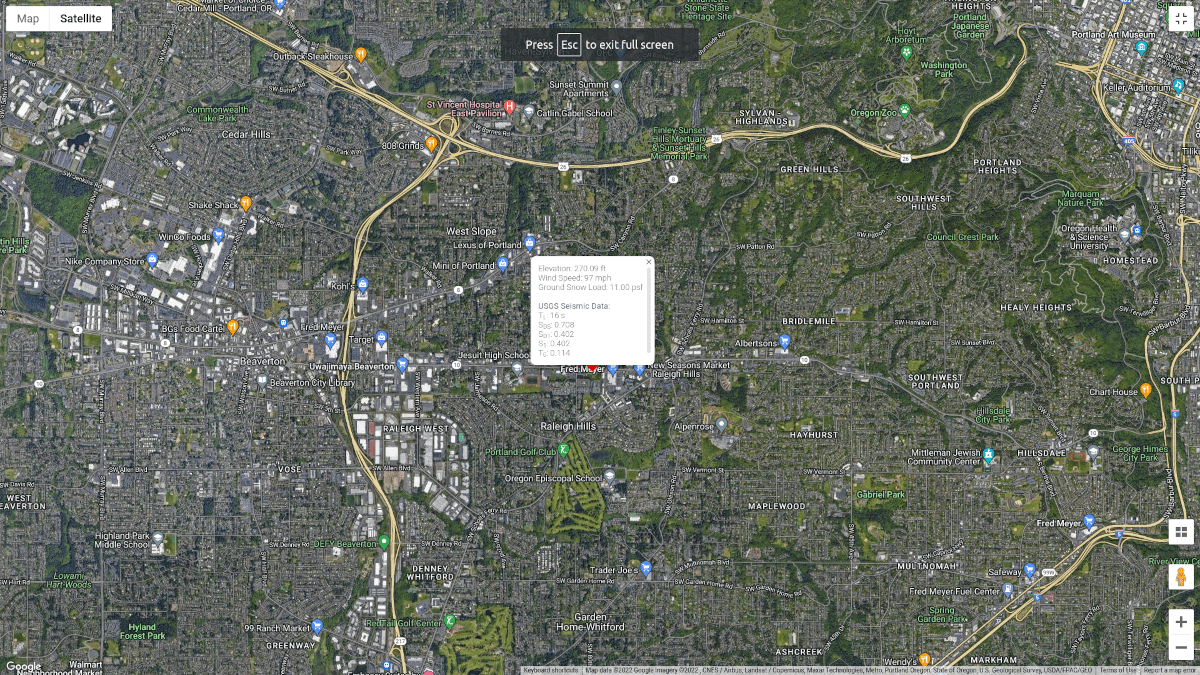
Figure 1. Site location (from Google Maps).
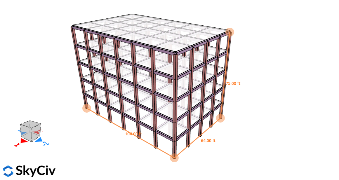
Figure 2. Structure for this example.
USGS Seismic Data
USGS has an open-source site seismic data which can be used from their Design Web Services API. In this calculation, we will only need the following data:
- \({S}_{D1}\) is the design spectral response acceleration parameters at a period of 1.0 s
- \({S}_{1}\) is the mapped maximum considered earthquake spectral response acceleration parameters
- \({S}_{DS}\)is the design spectral response acceleration parameter in the short period range
- \({T}_{L}\) is the long-period transition period
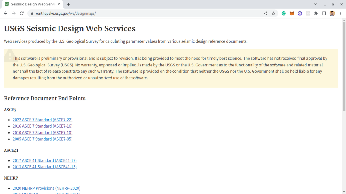
Figure 3. USGS Seismic Design Web Services.
In order to request the data above we will need the following data:
- Latitude, Longitude which we can get from Google Maps
- Risk Category of the structure based on Section 1.5 of ASCE 7-16
- Site Class based on Table 20.3-1 of ASCE 7-16
Equivalent Lateral Force Procedure
The seismic design base shear can be calculated using Equation 12.8-1 of ASCE 7-16:
\( V = {C}_{S} W \) (Eq. 12.8-1)
Where:
\( V \) is the seismic design base shear
\( {C}_{s} \) is the seismic response coefficient based on Section 12.8.1.1
\( W \) is the effective seismic weight as per Section 12.7.2
The formula for determining the seismic response coefficient is:
\( {C}_{s} = \frac{{S}_{DS}}{ \frac { R }{ {I}_{e} } } \) (Eq. 12.8-2)
Where:
\( {S}_{DS} \) is the design spectral response acceleration parameter in the short period range (from USGS Data)
\( R \) is the response modification factor as per Table 12.2-1
\( {I}_{e} \) is the importance factor determined from Section 11.5.1
However, we need to satisfy Equations 12.8-3 to 12.8-6:
The value of \({C}_{s}\) should not exceed 12.8-3 or 12.8-4
For \( T ≤ {T}_{L}\):
\({C}_{s,max} = \frac { {S}_{D1}}{ \frac{T R}{{I}_{e}}} \) (Eq. 12.8-3)
For \( T > {T}_{L}\) :
\({C}_{s,max} = \frac { {S}_{D1} {T}_{L} }{ \frac{ {T}^{2} R}{{I}_{e}}} \) (Eq. 12.8-4)
Moreover, \( {C}_{s} \) shall not be less than Equation 12.8-5
\( {C}_{s,min} = 0.044 {S}_{DS} {I}_{e} ≥ 0.01 \) (Eq. 12.8-5)
In addition, for structures located where \( {S}_{1} ≥ 0.6g\):
\( {C}_{s,min} = 0.5 \frac {{S}_{1}} { \frac{R}{{I}_{e}}} \) (Eq. 12.8-6)
Where
\( {S}_{D1} \) is the design spectral response acceleration parameter at period of 1.0 s (from USGS Data)
\( T \) is the fundamental period of the structure
\( {T}_{L} \) is the long period transition period (from USGS Data)
\( {S}_{1} \) is the mapped maximum considered earthquake spectral response acceleration parameter (from USGS Data)
Once we calculate the value of the seismic design base shear \( V \), we need to distribute the forces along the height of the structure using Section 12.8.3 of ASCE 7-16. In this example, we will assume that the structure has no vertical or horizontal irregularities.
\( {F}_{x} ={C}_{vx} V \) (Eq. 12.8-11)
\( {C}_{vx} = \frac {{w}_{x}{{h}_{x}}^{k}} { \sum_{i=1}^n{w}_{i}{{h}_{i}}^{k}} \) (Eq. 12.8-12)
Where
\( {C}_{vx} \) is the vertical distribution factor
\( {w}_{i} \) and \( {w}_{x} \) is the portion of the total effective seismic weight of the structure \( W \) located or assigned to level i or x
\( {h}_{i} \) and \( {h}_{x} \) is the height from the base to level i or x
\( k \) is defined as the following:
- \( k = 1 \) for structures with \( T ≤ 0.5 s\)
- \( k = 2 \) for structures with \( T ≥ 2.5 s\)
- linear interpolation of \( k \) for \( 0.5 < T < 2.5 s \)
In addition, floor and roof diaphragm forces can be determined using Section 12.10.1 of ASCE 7-16. The design force can be calculated using Equations 12.10-1 to 12.10-3:
\( {F}_{px} =\frac { \sum_{i=x}^n {F}_{i}} { \sum_{i=x}^n {w}_{i} }{w}_{px} \) (Eq. 12.10-1)
\( {F}_{px,min} = 0.2 {S}_{DS}{I}_{e}{w}_{px} \) (Eq. 12.10-2)
\( {F}_{px,max} = 0.4 {S}_{DS}{I}_{e}{w}_{px} \) (Eq. 12.10-3)
Where
\( {F}_{px} \) is the diaphragm design force at level x
\( {F}_{i} \) is the design force applied at level i
\( {w}_{i} \) is the weight tributary to level i
\( {w}_{px} \) is the weight tributary to diaphragm at level x
We will dive deeper into these parameters below and apply the concept to our structure.
Importance Factor, \( {I}_{e} \)
The importance factor, \( {I}_{e} \), for the structure can be determined from Section 11.5.1 which points to Table 1.5-2 of ASCE 7-16.
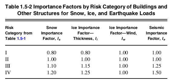
Figure 4. Table 1.5-2 of ASCE 7-16 indicating importance factor values per Risk Category.
Since the structure falls under Risk Category II, the corresponding importance factor \( I_{e} \) is equal to 1.0 based on Table 1.5-2.
\( {I}_{e} = 1.0 \)
Response Modification Factor, \( R \)
The response modification factor, \( R \), can be determined from Table 12.2-1 depending on the structural system used. In this example, we will assume that the structural system used is “Special Reinforced Concrete Moment Frames” for both X and Z directions. From this, we can determine that value of \( R \) is equal to 8 as per Table 12.2-1.
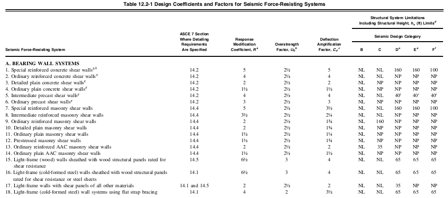
Figure 5. Truncated values of Table 12.2-1 of ASCE 7-16 indicating Response Modification Coefficient, \( R \), per structural system.
Site Class
To calculate for our seismic load, the location we will be using is at Raleigh Hills, Portland, OR, USA based on Seismic Loads: Guide to the Seismic Load Provisions of ASCE 7-16 (Charney et al., 2020) which is classified as Site Class C.
USGS Seismic Data
.The USGS Seismic Data for the location are the following:
SkyCiv now integrated the site seismic data from USGS Web API. Try our SkyCiv Load Generator!
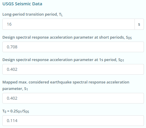
Figure 6. Site seismic data from USGS Web Services.
\({S}_{D1} = 0.402 \)
\({S}_{1} = 0.402 \)
\({S}_{DS} = 0.708 \)
\({T}_{L} = 16 s \)
\({T}_{0} = 0.114 \)
Seismic Design Category
Section 11.6 of ASCE 7-16 details how the procedure in determining the Seismic Design Category of the structure based on the Risk Category and Site Class for the structure.
- For \({S}_{1} ≥ 0.75 \) and Risk Category I, II, or III, the Seismic Design Category shall be assigned to Seismic Design Category E
- For \({S}_{1} ≥ 0.75 \) and Risk Category IV, the Seismic Design Category shall be assigned to Seismic Design Category F
- Otherwise, Table 11.6-1 and Table 11.6-2 shall be used, whichever is more severe.
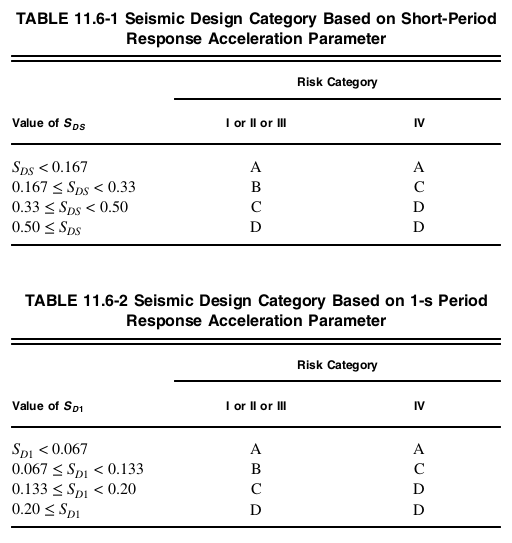
Figure 7. Seismic design category from Section 11.6 of ASCE 7-16.
For this structure, with Risk Category II, \({S}_{D1} = 0.402 \), and \({S}_{DS} = 0.708 \) the Seismic Design Category is D based on both tables 11.6-1 and 11.6-2 of ASCE 7-16. The Seismic Design Category will be used for redundancy factor \( ρ \) in calculating diaphragm design forces.
Fundamental Period of the Structure \( T \)
The fundamental period of a structure can be determined from the modal analysis of the structure. ASCE 7-16 allows the approximation of the fundamental period of a structure using Section 12.8.2.1.
\( {T}_{a} = {C}_{t} {{h}_{n}}^{x} \)
Where \( {h}_{n} \) is the structural height of the structure (vertical distance from the base to the highest level of the seismic force-resisting system of the structure), and \( {C}_{t} \) and \( x \) can be determined from Table 12.8-2.
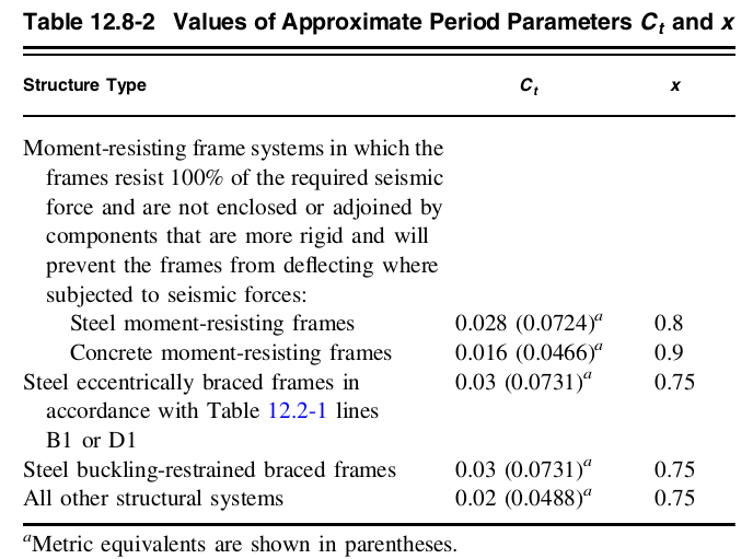
Figure 8. Values of \( {C}_{t} \) and \( x \) from Table 12.8-2 of ASCE 7-16.
Since the structure is a concrete moment-resisting frame:
\( {C}_{t} = 0.016\)
\( x = 0.9\)
Therefore, using structure height \( {h}_{n} \) equal to 75 ft., the approximate fundamental period of the structure \( {T}_{a} \) can be determined:
\( {T}_{a} = {C}_{t} {{h}_{n}}^{x} = (0.016) {(75)}^{0.9}\)
\( T = {T}_{a} = 0.7792 s\)
Seismic Response Coefficient \({C}_{s}\)
From the values above, we can already calculate for Seismic Response Coefficient \({C}_{s}\):
\( {C}_{s} = \frac{ {S}_{DS} }{ \frac {R}{{I}_{e}} } = \frac{ 0.402 }{ \frac {8}{1.0} } \)
\( {C}_{s} = 0.0885\)
Since \( T ≤ {T}_{L}\):
\({C}_{s,max} = \frac { {S}_{D1}}{ \frac{T R}{{I}_{e}}} = \frac { (0.402)}{ \frac{(0.7792)(8)}{(1.0)}} \)
\({C}_{s,max} = 0.0645 \)
In addition, the minimum value of \( {C}_{s} \) shall not be less than:
\( {C}_{s,min} = 0.044 {S}_{DS} {I}_{e} ≥ 0.01 \)
\( {C}_{s,min} = 0.044 (0.402) (1.0) ≥ 0.01 \)
\( {C}_{s,min} = 0.0312 \)
The final value of \( {C}_{s} \) to be used in calculation shall be:
\( {C}_{s} = 0.0645\)
Effective Seismic Weight \( W \)
In this example, we will calculate the effective seismic weight using the dead and superimposed dead load applied to floors. External and internal walls are assumed to be incorporated in the superimposed floor dead load equal to 100 psf. Using concrete unit weight equal to 156 lb/cu.ft.:
For typical floor level (excluding ground and roof levels):
Column: Typical story height x cross-sectional area x unit weight of concrete x total no. of columns = 15 ft x 156 lb/cu.ft. x (20″x20″) x 35 = 227.5 kips
Slab: Floor area x thickness x unit weight of concrete = 64ft (104 ft) x 8″ x 156 lb/cu.ft. = 692.224 kips
Beams: Total length x cross-sectional area x unit weight of concrete = 968 ft x 156 lb/cu.ft. x (14″x20″) = 293.627 kips
Superimposed dead load: Floor area x load= 64ft (104 ft) x 100 psf= 665.6 kips
Total dead load per level: 1878.951 kips
For roof level:
Column: Typical story height x cross-sectional area x unit weight of concrete x total no. of columns = 7.5 ft x 156 lb/cu.ft. x (20″x20″) x 35 = 113.75 kips
Slab: Floor area x thickness x unit weight of concrete = 64ft (104 ft) x 8″ x 156 lb/cu.ft. = 692.224 kips
Beams: Total length x cross-sectional area x unit weight of concrete = 968 ft x 156 lb/cu.ft. x (14″x20″) = 293.627 kips
Superimposed dead load: Floor area x load= 64ft (104 ft) x 50 psf= 332.8 kips
Total dead load at roof level: 1432.401 kips
In summary:
| Floor Level | Elevation, ft | Weight, wx, kips |
| Roof | 75 | 1432.401 |
| 5th level | 60 | 1878.951 |
| 4th level | 45 | 1878.951 |
| 3rd level | 30 | 1878.951 |
| 2nd level | 15 | 1878.951 |
| Effective Seismic Weight, W | 8948.203 | |
\( W = 8949.203 kips\)
Seismic Base Shear \( V \)
Using Equation 12.8-1 of ASCE 7-16, the seismic base shear can be calculated:
\( V = {C}_{S} W = (0.0645)(8948.203) \)
\( V = 577.159 kips \)
Vertical Distribution of Seismic Forces \( {F}_{x} \)
We need to distribute the seismic load throughout the structure. Since the fundamental period of the structure is \( T = {T}_{a} = 0.7792 s\), therefore:
\( k = 1.1396\)
To calculate the seismic force \( {F}_{x} \) per level, the best approach is to tabulate the seismic weights per level:
| Floor Level | \( {w}_{x} \) kips | \( {h}_{x} \) ft | \( {w}_{x} {{h}_{x}}^{k} \) | \( {C}_{vx} \) |
\( {F}_{x} \) kips |
| Roof | 1432.401 | 75 | 196303.644 | 0.2923 | 168.6950 |
| 5th level | 1878.951 | 60 | 199681.715 | 0.2973 | 171.5980 |
| 4th level | 1878.951 | 45 | 143865.010 | 0.2142 | 123.6315 |
| 3rd level | 1878.951 | 30 | 90631.141 | 0.1349 | 77.8845 |
| 2nd level | 1878.951 | 15 | 41135.482 | 0.0612 | 35.3501 |
| Σ = 671616.992 | \( V \) = 577.1591 |
Diaphragm Forces \( {F}_{px} \)
The calculation of the diaphragm forces are shown below. Since we assumed there are no irregularities, the redundancy factor \( ρ \) is set to 1.0. This parameter shall be multiplied to \( {F}_{px} \):
| Floor Level | \( {w}_{px} \) kips | \( Σ {w}_{i} \) |
\( Σ {F}_{i} \) | \( {F}_{px,min} \) | \( {F}_{px,max} \) | \( {F}_{px} \) | Design \( {F}_{px} \) |
| Roof | 1432.401 | 1432.401 | 168.6950 | 202.8279 | 405.6559 | 168.6950 | 202.8279 |
| 5th level | 1878.951 | 3311.351 | 340.2930 | 266.0594 | 532.1188 | 193.0915 | 266.0594 |
| 4th level | 1878.951 | 5190.302 | 463.9245 | 266.0594 | 532.1188 | 167.9461 | 266.0594 |
| 3rd level | 1878.951 | 7069.253 | 541.8090 | 266.0594 | 532.1188 | 144.0085 | 266.0594 |
| 2nd level | 1878.951 | 8948.203 | 577.1591 | 266.0594 | 532.1188 | 121.1923 |
266.0594 |
SkyCiv Load Generator
All these calculations are already incorporated in the SkyCiv Load Generator. Streamline your calculation using our Free Seismic Load Calculator for ASCE 7-16!
Site Seismic Data
The USGS Seismic Data can be obtained once the Risk Category, Site Class, and Project Address are defined. Note that the parameters \({S}_{D1} \), \({S}_{1} \), \({S}_{DS} \), and \({T}_{L} \) should have values in order to proceed with the Seismic Load Calculation.
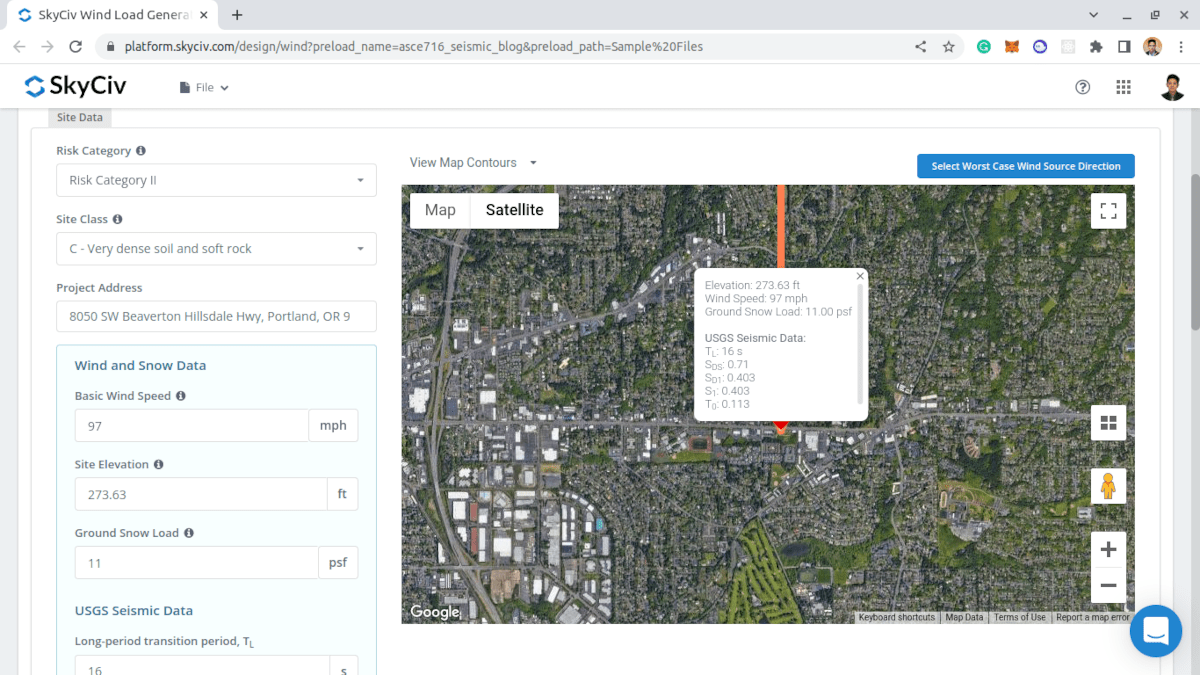 Figure 9. Parameters needed to get the USGS Seismic data for the location.

Figure 9. Results from USGS Seismic data.
Users can modify the parameters obtained from USGS Web Services to obtain the most appropriate seismic load for the structure.
Structure Data
On the Structure Data tab, you just need to define the standard building data: Roof Profile, Building Length, Building Width, Mean Roof Height, and Roof Pitch Angle.
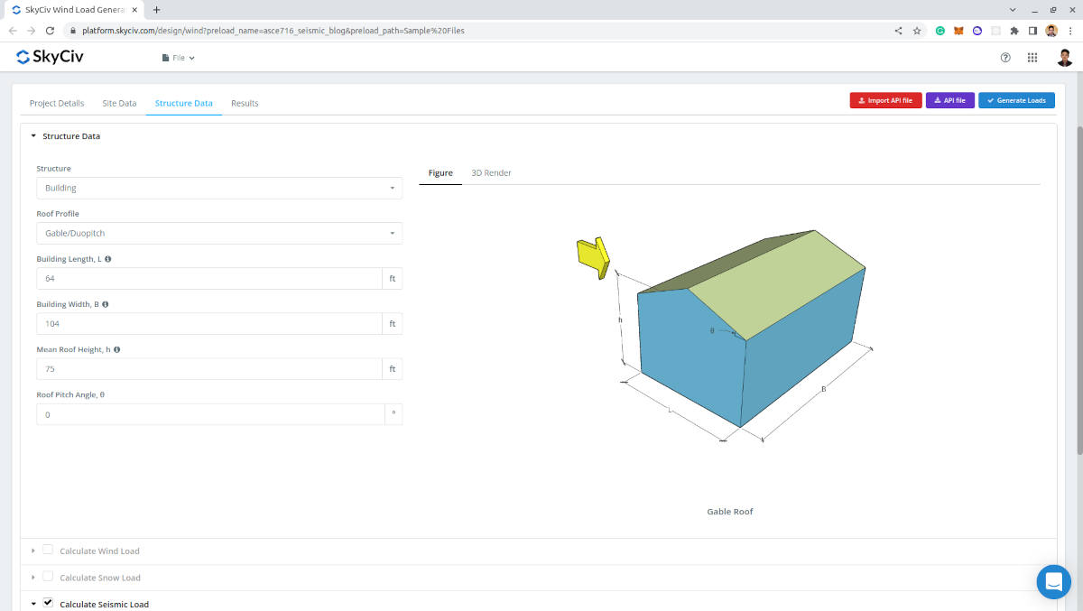
Figure 10. Building data input.
Seismic Data
To proceed with the seismic calculations, the required are the following:
- Structure system – for determining the values of \({C}_{t} \) and \(x \) which will be used in calculating the approximate fundamental period of the structure \({T}_{a} \)
- Approximate fundamental period of the structure \({T}_{a} \) – can be user-defined to more appropriate seismic load calculation
- Response Modification Factor \( R \) – default value is 8.5 and be modified for more appropriate seismic results
- Redundancy factor, \( ρ \) – default value is 1.0 and can be modified. Used in diaphragm forces calculation
- Floor Weights – used for the vertical distribution of base shear and for diaphragm forces. Data per level required are: Level (for designation), Elevation, and Weight
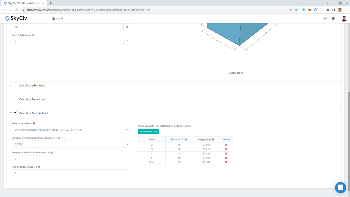
Figure 11. Seismic parameters required for the seismic calculation.
Results
The output of the calculation is the seismic parameters used and the calculated seismic base shear \(V \), seismic forces per level, and diaphragm forces per level.
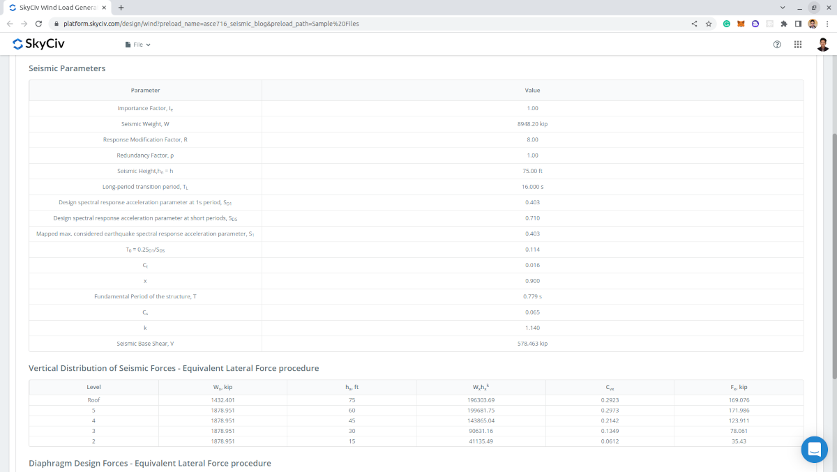
Figure 12. Input parameters and results for seismic load calculation.
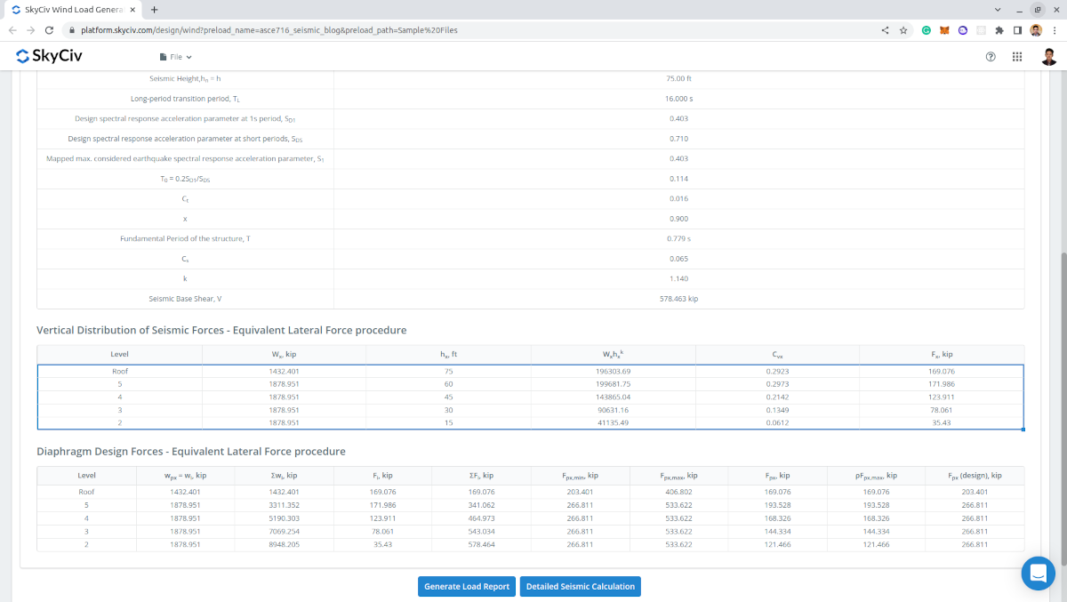
Figure 13. Tabulated seismic forces per level including the diaphragm design forces.
Detailed Report
Upon generating the results, Professional account users and those who purchased the standalone load generator module can generate a detailed seismic calculation. The report displays all the parameters and assumptions used in the seismic calculation to make it transparent to the user. The generated report for this example calculation can be accessed through this link.
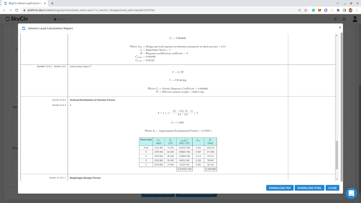
Figure 14. Detailed seismic load calculation of SkyCiv Load Generator.
Take advantage of this feature by signing up for a Professional Account or by purchasing the standalone Load Generator module! For existing users, a FREE DEMO is also available if you require a more comprehensive solution for load calculations.
For additional resources, you can use these links:

Structural Engineer, Product Development
MS Civil Engineering
References:
- American Society of Civil Engineers. (2017, June). Minimum design loads and associated criteria for buildings and other structures. American Society of Civil Engineers.
- Charney, F., Heausler, T., and Marshall, J. (2020). Seismic loads: Guide to the seismic load provisions of ASCE 7-16. American Society of Civil Engineers.
- Google Maps