How to offset, translate or add insertion points to a member in SkyCiv Structural 3D
Member offsets are small displacements to a member’s position to a location closer to its real world representation.
By default, SkyCiv’s S3D software joins members node to node. The one-dimensional line representing each member between their end nodes is located at the cross section’s centroid.
Aesthetically, this default behaviour creates an overlap of some members which realistically could not occur. In addition, small moments or forces can be present in real world structures due to the adjacent members not actually being joined centroid to centroid. Member offsets are hence used to fix these issues.
Offset Axis
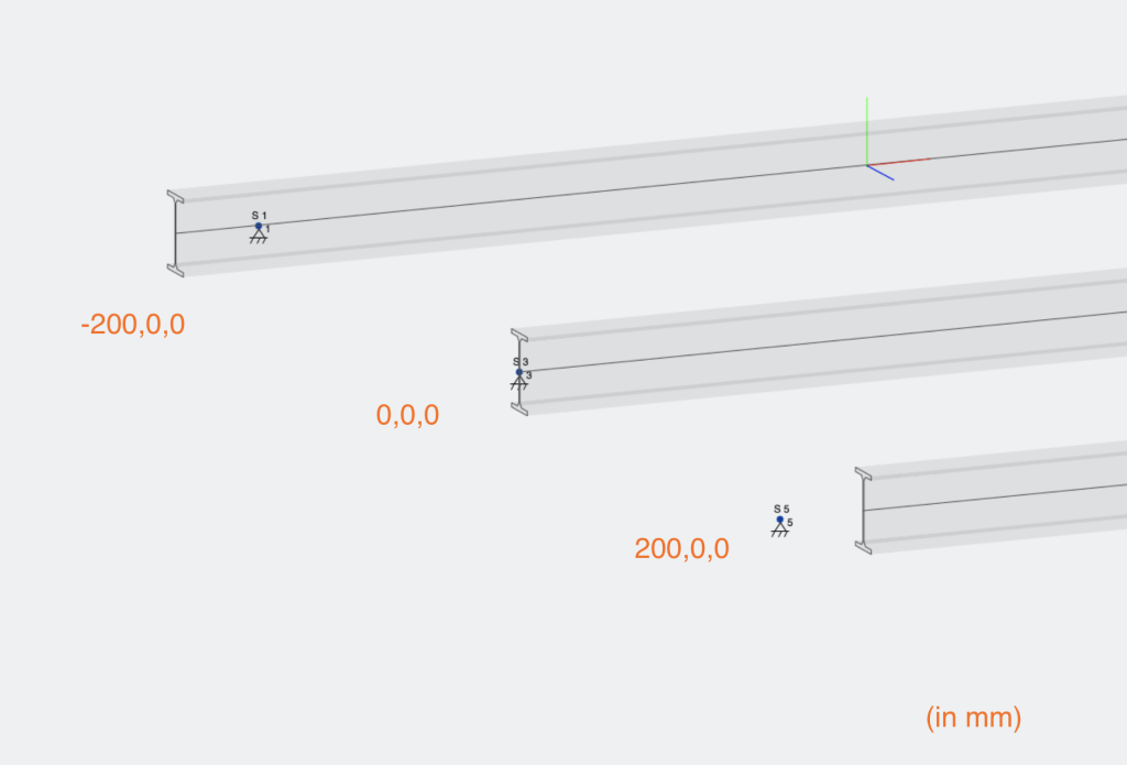
Member offsets are defined by a three string input representing the offset distance in each axis direction: [x-axis, y-axis, z-axis]. This specifies that the members is offset by a specified value of millimetres (inches if using Imperial) in the direction of the designated local axis. The local axis must be used for the offset command due to the confusion that can arise within a three dimensional space when two members are on two totally different planes. For example if a members is on a diagonal to the global axis offsetting it via global measurements would be difficult and time consuming.
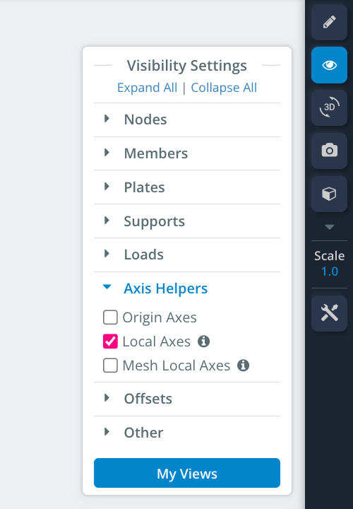
Member local axis’ can be displayed onto the wire framed view by going into the visibility settings and turning them on as shown below:
Offsetting a member
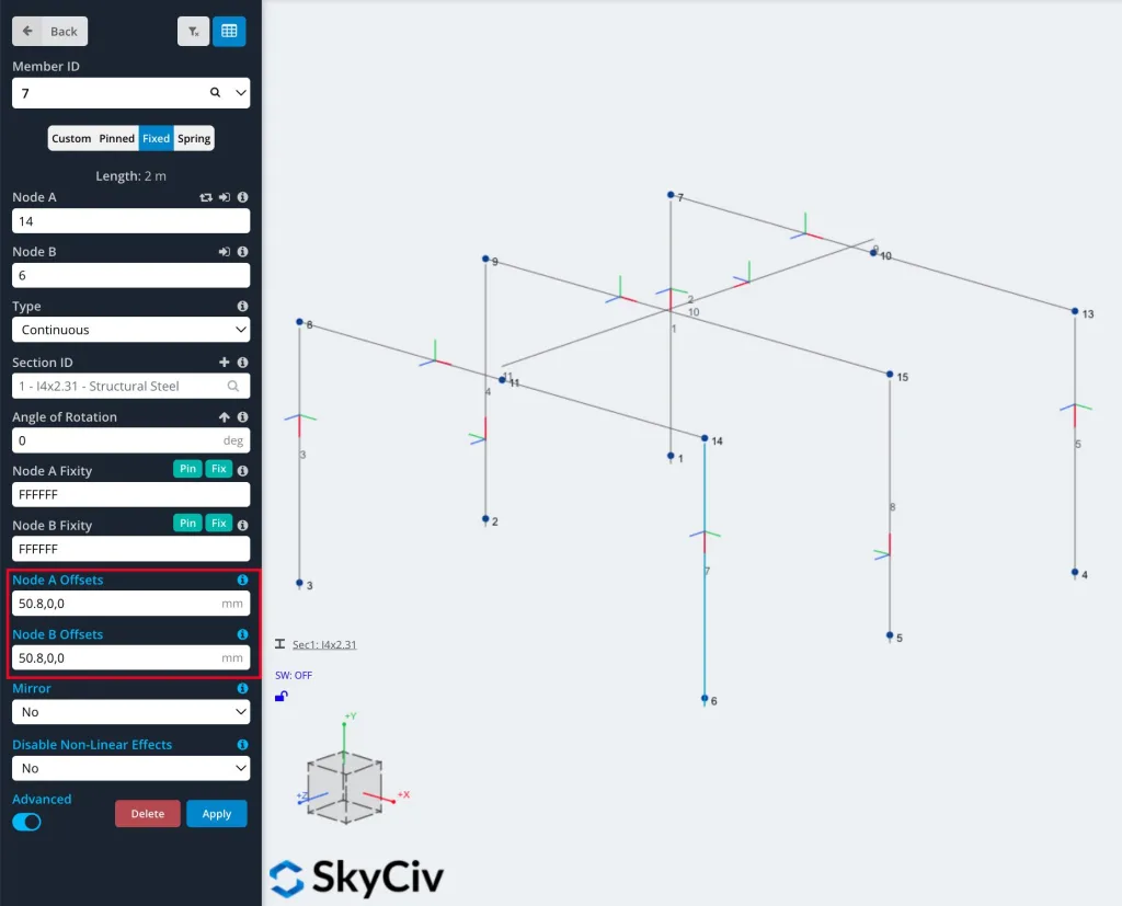
A member can be offset by clicking on the member and entering the value of the offset in the corresponding axis section of the following [x-axis, y-axis, z-axis], originally set as [0,0,0] due to the lack of initial offset. Using a negative number will offset the member in the negative direction as the local axis.
To access the offset options, make sure you’ve toggled the “Advanced” switch to the on position.
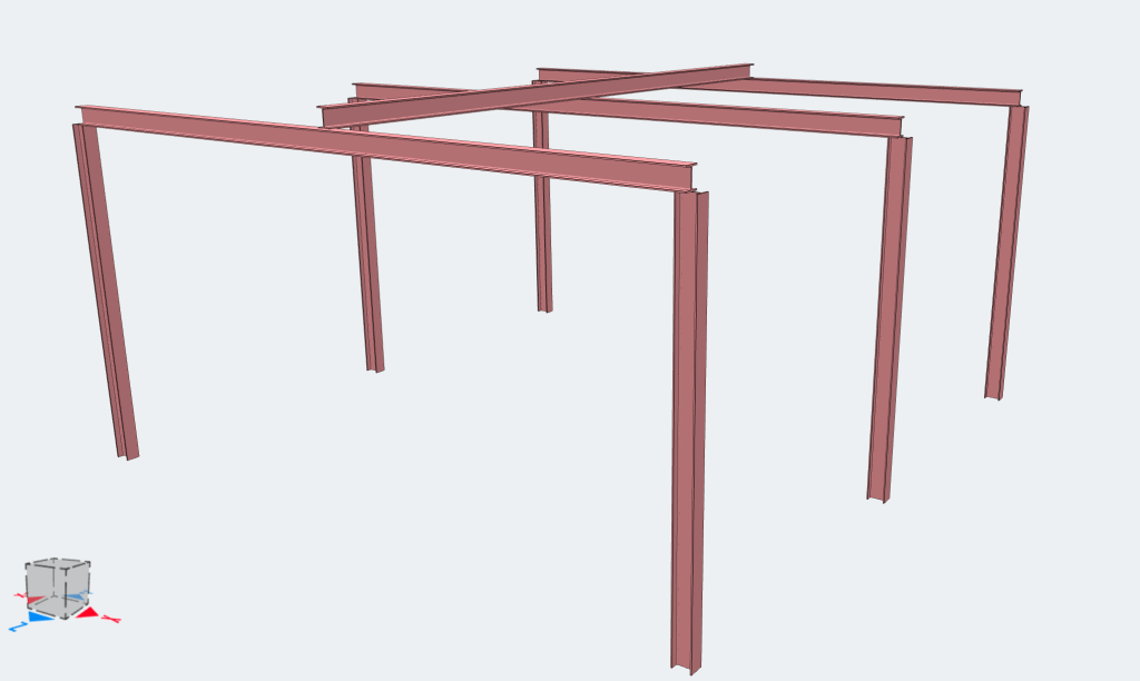
Shown below is an example of a frame without any member offsets. Note that offsets to a member can be made at a single end or both ends.
You can see above that the corners of the frame members are over lapping and that the purlin is sitting within the frame rafter rather than on top.
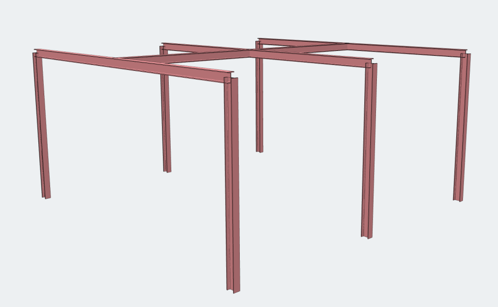
Shown below is the same frame but with the use of member offsets:
You can see above that the rafters now sit on top of the columns instead of within them and the similarly with the purlins on the rafters.
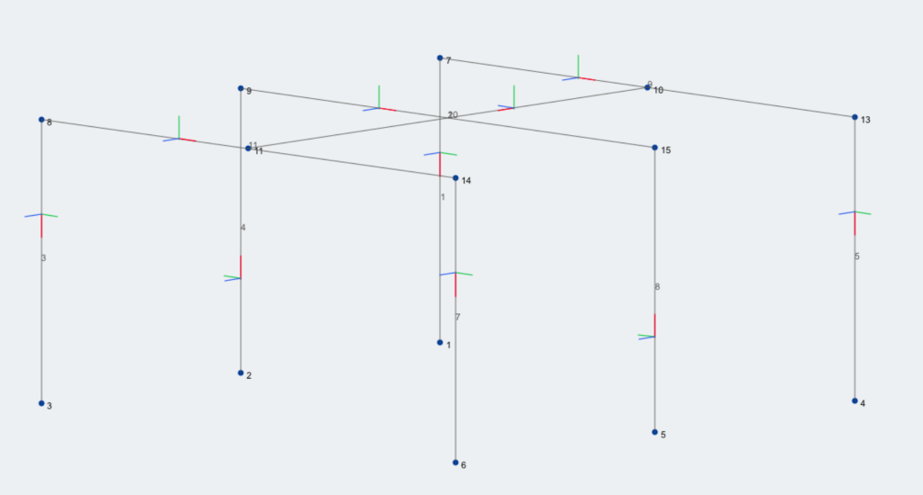
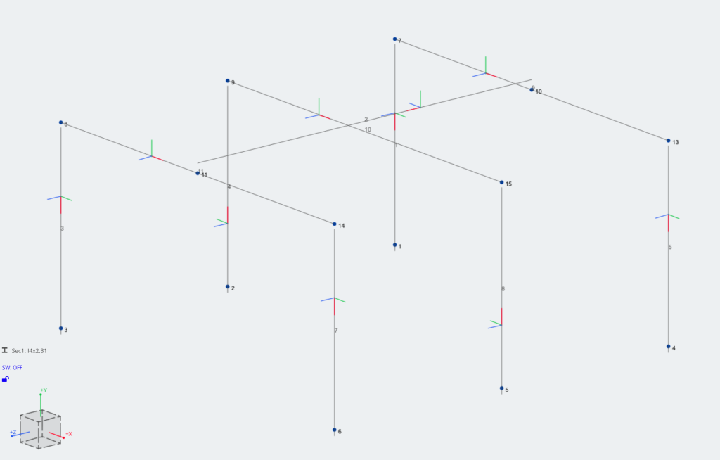
Shown below is the same frame but in the wired frame view:
How do Offsets work?
Offsets will create “space” between a member and its node, but still connected to the node. It is connected by an invisible Rigid Link. A rigid link is an imaginary stiff link that joins the node to the member offset location, such that they perfectly translate loads, deflection and rotations to one another.
Since the members are no longer connected at their midpoints, this rigid link will create a small moment arm and will therefore affect the member’s internal member forces. It can create additional torsional or bending moment forces in the member. A lot of the time these values are fairly minimal and often can be considered negligible.
Read more about rigid links and their behaviour in the Member documentation.
Note when using Offsets
It is important to be careful when using offsets and rigid links to ensure the members are still connected properly. For instance, if you attach a rigid link to a FFFRRR support (fixed translation is all directions – free to rotate in all directions), you might expect that member to still be supported in the X,Y,Z translation. However, the rigid link is technically free to rotate and the forces may not transfer as intended:
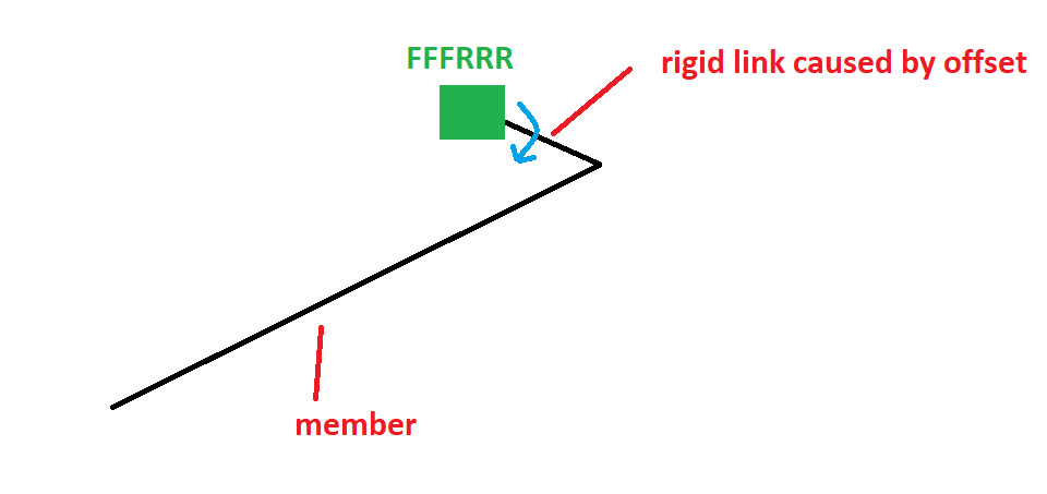
(Note: In this case a correct set up may be a fully fixed support and then FFFRRR on the end of the member to restrain the rigid member from rotating)
Insertion Points
Insertion Points are a common way to control the positioning of the connection to a member. By default, the member will be connected to other elements via its centroid. With insertion points, you can move this to other key points of the section. Insertion Points are built on the same functionality as offsets to balance the accuracy of the software with a clean and easy user experience.
Insertion points are easy to control using Member Offsets:
Insertion Points can be defined by the following:
- First Entry – number only
- Second Entry – top, bottom, shear or center
- Third Entry – right, left, shear or center
- Fourth Entry – (Optional) By adding a 4th argument as “visual”, the solver will ignore the offsets in the analysis, and use them only in the graphics.
By combining these options, users can move their insertion points to where they need on the member:
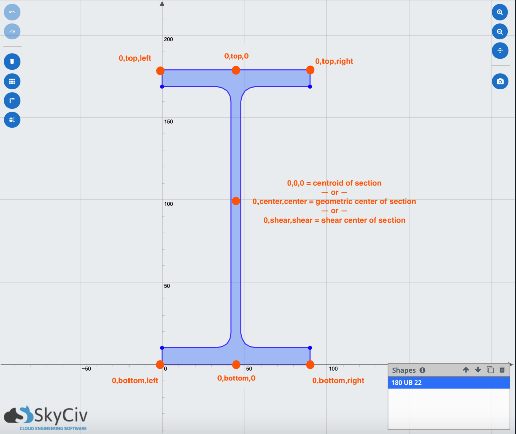
Some Common Insertion Points of a Beam – note: users can mix and match the different inputs
Some common examples:
| 0,top,0 | Insertion point to top of beam |
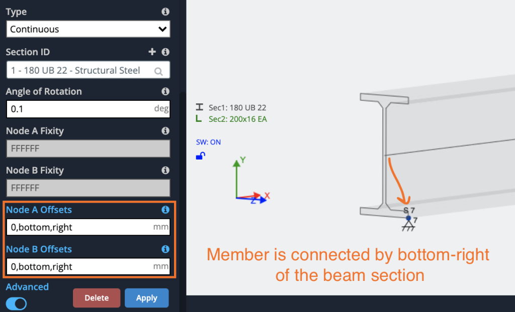
| 0,top,right | Insertion point to top right of beam |
| 0,bottom,left,visual | Insertion point to bottom left of beam, ignore offset in analysis (only use for visualisation) |
| 0,shear,shear | Insertion point to section shear centre |
| 0,0,right | Insertion point to centroid-right of the beam |
| 0,t,r | Insertion point to top-right of the beam |
Note: for all of the above inputs, users can enter in just the first letter as a shortcut. E.g. “0,t,l” would be the same as entering “0, top, left”
The Effects of Insertion Points
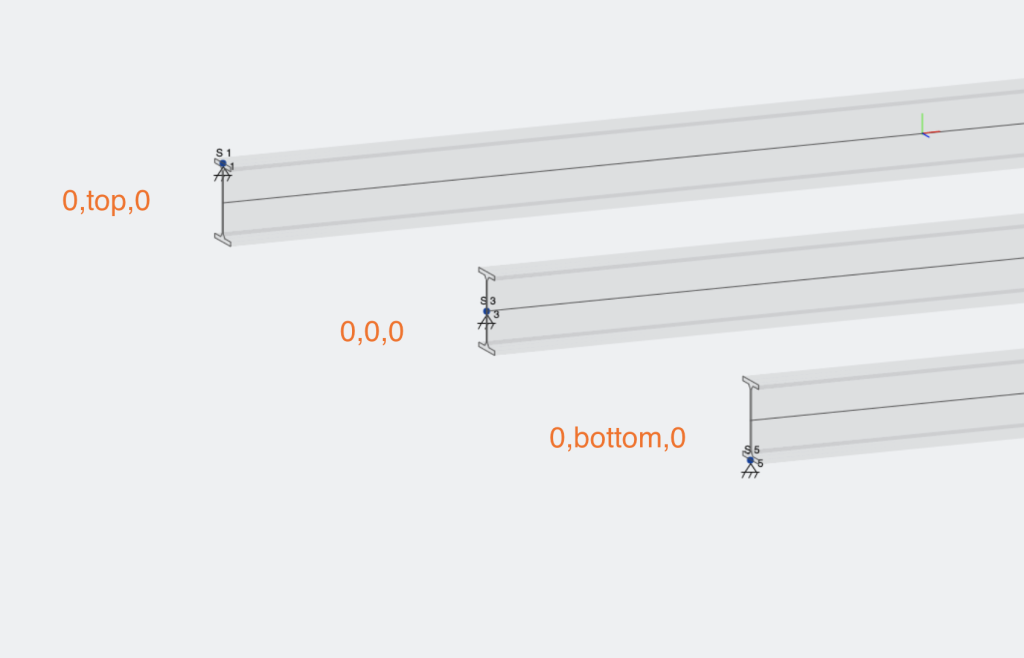
Below are some examples of the effects of different insertion points. By including an insertion point, a rigid member will be introduced at the member ends in order to offset the location of the centroid. So in the below example, we have three possible insertion points:
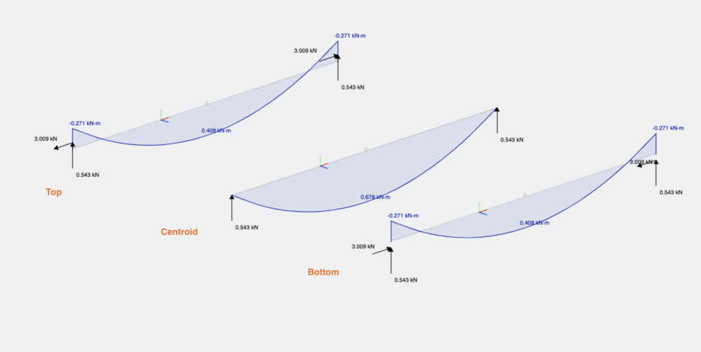
The different insertion points will have different effects on both the deflection, reactions and member bending moment diagrams:
Insertion points (offsets) can also exist along a member by entering in a number as the first input, here are 3 examples of such: