How to calculate the ultimate load-carrying capacity of a single pile
Load-Carrying Capacity
Evaluating the ultimate load-carrying capacity of a single pile is one of the most important aspects of pile design, and can sometimes be complicated. This article will walk through the governing equations for single pile design as well as an example.
To easily understand the load transfer mechanism of a single pile, imagine a concrete pile of length L with diameter D, as shown in Figure 1.
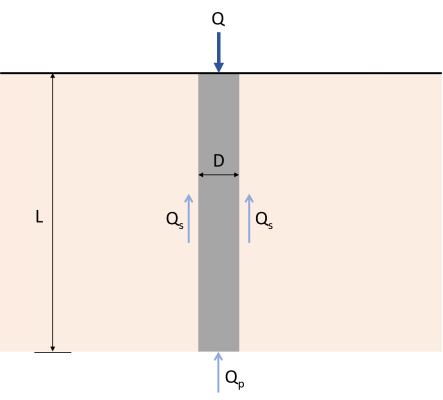
Figure 1: Load transfer Mechanism for piles
The load Q applied on the pile shall be transferred directly to the soil at the bottom of the pile. Part of this load will be resisted by the sides of the pile using something called “skin friction” developed along the shaft (Qs), and the rest will be resisted by the soil that the pile is bearing on (Qp). Therefore, the ultimate load-carrying capacity (Qu) of a pile shall be given by the equation (1). There are multiple methods available to estimate the values of Qp and Qs.
\( {Q}_{u} = {Q}_{p} + {Q}_{s} \) (1)
Qu = Ultimate load-carrying capacity
Qp = End-bearing load capacity
Qs = Skin-frictional resistance
Want to try SkyCiv’s Foundation Design software? Our free tool allows users to perform load-carrying calculations without any download or installation!
End-bearing Capacity, Qp
Ultimate end-bearing capacity is theoretically the maximum load per unit area that can be supported by the soil in bearing, without failure. The following equation of Karl Von Terzaghi, the father of soil mechanics, is one of the first and most commonly used theory when evaluating the ultimate bearing capacity of foundations. Terzaghi’s equation for ultimate bearing capacity can be expressed as:
\( {q}_{u} = (c × {N}_{c}) + (q × {N}_{q}) + (\frac{1}{2} × γ × B × {N}_{γ}) \) (2)
qu = Ultimate end-bearing capacity
c = Cohesion of soil
q = Effective soil pressure
γ = Soil unit weight
B = Cross-sectional depth or diameter
Nc, Nq, Nγ = Bearing factors
Since qu is in terms of load per unit area or pressure, multiplying it by the cross-sectional area of the pile will result in the end-bearing load capacity (Qp) of the pile. The resulting value of the last term of Equation 2 is negligible due to a relatively small pile width, hence, it may be dropped from the equation. Thus, the ultimate end-bearing load capacity of the pile can be expressed as shown in equation (3). This modified version of Terzaghi’s equation is used in the SkyCiv Foundation module when designing piles.
\( {Q}_{p} = {A}_{p} × [(c × {N}_{c}) + (q × {N}_{q}) ] \) (3)
Ap = Cross-sectional area of pile
Bearing factors Nc and Nq are non-dimensional, empirically derived, and are functions of the soil friction angle (Φ). Researchers have already completed the calculations required to find bearing factors. Table 1 summarizes the values of Nq according to Naval Facilities Engineering Command (NAVFAC DM 7.2, 1984). The value of Nc is approximately equal to 9 for piles under clayey soils.
| Bearing Factor (Nq) | |||||||||||||
|---|---|---|---|---|---|---|---|---|---|---|---|---|---|
| Friction Angle (Ø) | 26 | 28 | 30 | 31 | 32 | 33 | 34 | 35 | 36 | 37 | 38 | 39 | 40 |
| Driven Piles | 10 | 15 | 21 | 24 | 29 | 35 | 42 | 50 | 62 | 77 | 86 | 120 | 145 |
| Bored Piles | 5 | 8 | 10 | 12 | 14 | 17 | 21 | 25 | 30 | 38 | 43 | 60 | 72 |
Table 1: Nq values from NAVFAC DM 7.2
Skin-frictional Resistance Capacity, Qs
Skin-frictional resistance of piles is developed along the length of the pile. Generally, the frictional resistance of a pile is expressed as:
\( {Q}_{s} = ∑ (p × ΔL × f) \) (4)
p = Perimeter of the pile
ΔL = Incremental pile length over which p and f are taken
f = Unit frictional resistance at any depth
Estimating the value of the unit frictional resistance (f) requires several important factors to consider, such as the nature of pile installation and soil classification. Equations (5) and (6) shows the computational method to find the unit frictional resistance of piles in sandy and clayey soils, respectively. Tables 2 and 3 present the recommended effective earth pressure coefficient (K) and the soil-pile frictional angle (δ’), according to NAVFAC DM7.2.
For sandy soils:
\( f = K × σ’× tan(δ’) \) (5)
K = Effective earth pressure coefficient
σ’ = Effective vertical stress at the depth under consideration
δ’ = Soil-pile frictional angle
For clayey soils:
\( f = α × c \) (6)
α = Empirical adhesion factor
| Soil-Pile Frictional Angle (δ’) | |
|---|---|
| Pile Type | δ’ |
| Steel Pile | 20º |
| Timber Pile | 3/4 × Φ |
| Concrete Pile | 3/4 × Φ |
Table 2: Soil-Pile Frictional Angle Values (NAVFAC DM7.2, 1984)
| Lateral Earth Pressure Coefficient (K) | ||
|---|---|---|
| Pile Type | Compression Pile | Tension Pile |
| Driven H-piles | 0.5-1.0 | 0.3-0.5 |
| Driven displacement piles (round, rectangular) | 1.0-1.5 | 0.6-1.0 |
| Driven displacement piles (tapered) | 1.5-2.0 | 1.0-1.3 |
| Driven jetted piles | 0.4-0.9 | 0.3-0.6 |
| Bored piles (<24″ Diameter) | 0.7 | 0.4 |
Table 3: Lateral Earth Pressure Coefficient (K) Values (NAVFAC DM7.2, 1984)
| Adhesion Factor (α) | |||||||||||||
|---|---|---|---|---|---|---|---|---|---|---|---|---|---|
| c/pa | α | ||||||||||||
| ≤ 0.1 | 1.00 | ||||||||||||
| 0.2 | 0.92 | ||||||||||||
| 0.3 | 0.82 | ||||||||||||
| 0.4 | 0.74 | ||||||||||||
| 0.6 | 0.62 | ||||||||||||
| 0.8 | 0.54 | ||||||||||||
| 1.0 | 0.48 | ||||||||||||
| 1.2 | 0.42 | ||||||||||||
| 1.4 | 0.40 | ||||||||||||
| 1.6 | 0.38 | ||||||||||||
| 1.8 | 0.36 | ||||||||||||
| 2.0 | 0.35 | ||||||||||||
| 2.4 | 0.34 | ||||||||||||
| 2.8 | 0.34 | ||||||||||||
Note: pa = atmospheric pressure ≈ 100 kN/m2
Table 4: Adhesion Factor Values (Terzaghi, Peck, and Mesri, 1996)
Example: Calculating the capacity of piles in sand
A 12-meter long concrete pile with a diameter of 500 mm is driven into multiple sand layers with no groundwater present. Find the ultimate load-carrying capacity (Qu) of the pile.
| Details | |
|---|---|
| Section | |
| Diameter | 500 mm |
| Length | 12 m |
| Layer 1-Soil Properties | |
| Thickness | 5 m |
| Unit Weight | 17.3 kN/m3 |
| Friction Angle | 30 Degrees |
| Cohesion | 0 kPa |
| Groundwater Table | Not present |
| Layer 2-Soil Properties | |
| Thickness | 7 m |
| Unit Weight | 16.9 kN/m3 |
| Friction Angle | 32 Degrees |
| Cohesion | 0 kPa |
| Groundwater Table | Not present |
Step 1: Compute the end-bearing load capacity (Qp).
At the tip of the pile:
Ap = (π/4) × D2 = (π/4) × 0.52
Ap = 0.196 m2
c = 0 kPa
θ = 32º
Nq = 29 (From Table 1)
Effective soil pressure (q):
q = (γ1 × t1) + (γ2 × t2) = (5 m × 17.3 kN/m3) + (7 m × 16.9 kN/m3)
q = 204.8 kPa
Then use equation (3) for the end-bearing load capacity:
Qp = Ap × [(c × Nc) + (q × Nq)]
Qp = 0.196 m2 × ( 204.8 KPa × 29)
Qp = 1,164.083 kN
Step 2: Compute the skin-frictional resistance (Qs).
Using equations (4) and (5), calculate the skin-frictional per soil layer.
Qs = ∑ (p × ΔL × f)
p = π × D = π × 0.5 m
p = 1.571 m
Layer 1:
ΔL = 5 m
f1 = K × σ’1× tan(δ’)
K = 1.25 (Table 3)
δ’ = 3/4 × 30º
δ’ = 22.50º
σ’1 = γ1 × (0.5 × t1) = 17.3 kN/m3 × (0.5 × 5 m)
σ’1 = 43.25 kN/m2
f1 = 1.25 × 43.25 kN/m2 × tan(22.50º)
f1 = 22.393 kN/m2
Qs1 = p × ΔL × f1 = 1.571 m ×5 m × 22.393 kN/m2
Qs1 = 175.897 kN
Layer 2:
ΔL = 7 m
f2 = K × σ’2× tan(δ’)
K = 1.25 (Table 3)
δ’ = 3/4× 32º
δ’ = 24º
σ’2 = (γ1 × t1) + [γ2 × (0.5 × t2)] = (17.3 kN/m3 × 5 m) + [16.9 kN/m3 ×(0.5 × 7 m)]
σ’2 = 145.65 kN/m2
f2 = 1.25 × 145.65 kN/m2 × tan(24º)
f2 = 81.059 kN/m2
Qs2 = p × ΔL × f2 = 1.571 m ×7 m × 81.059 kN/m2
Qs2 = 891.406 kN
Total skin-frictional resistance:
Qs = Qs1+ Qs2 = 175.897 kN + 891.406 kN
Qs = 1,067.303 kN
Step 3: Compute for the ultimate load-carrying capacity (Qu).
Qu = Qp+ Qs = 1,164.083 kN + 1,067.303 kN
Qu = 2,231.386 kN
Example 2: Calculating the capacity of piles in clay
Consider a 406 mm diameter concrete pile with a length of 30m embedded in layered, saturated clay. Find the ultimate load-carrying capacity (Qu) of the pile.
| Details | |
|---|---|
| Section | |
| Diameter | 406 mm |
| Length | 30 m |
| Layer 1-Soil Properties | |
| Thickness | 10 m |
| Unit Weight | 8 kN/m3 |
| Friction Angle | 0º |
| Cohesion | 30 kPa |
| Groundwater Table | 5 m |
| Layer 2-Soil Properties | |
| Thickness | 10 m |
| Unit Weight | 19.6 kN/m3 |
| Friction Angle | 0º |
| Cohesion | 0 kPa |
| Groundwater Table | Fully submerged |
Step 1: Compute the end-bearing load capacity (Qp).
At the tip of the pile:
Ap = (π/4) × D2= (π/4) × 0.4062
Ap = 0.129 m2
c = 100 kPa
Nc = 9 (Typical value for clay)
Qp = (c × Nc) × Ap = (100 kPa × 9) × 0.129 m2
Qp = 116.1 kN
Step 2: Compute the skin-frictional resistance (Qs).
Using equations (4) and (6), calculate the skin-frictional per soil layer.
Qs = ∑ (p × ΔL × f)
p = π × D = π × 0.406 m
p = 1.275 m
Layer 1:
ΔL = 10 m
α1 = 0.82 (Table 4)
c1 = 30 kPa
f1= α1 × c1 = 0.82 × 30 kPa
f1 = 24.6 kN/m2
Qs1 = p × ΔL × f1 = 1.275 m × 10 m × 24.6 kN/m2
Qs1 = 313.65 kN
Layer 2:
ΔL = 20 m
α2= 0.48 (Table 4)
c2 = 100 kPa
f2 = α2 × c2 = 0.48 × 100 kPa
f2 = 48 kN/m2
Qs2 = p × ΔL × f2 = 1.275 m × 20 m × 48 kN/m2
Qs2 = 1,224 kN
Total skin-frictional resistance:
Qs = Qs1+ Qs2 = 313.65 kN + 1224 kN
Qs = 1,537.65 kN
Step 3: Compute for the ultimate load-carrying capacity (Qu).
Qu = Qp+ Qs = 116.1 kN + 1537.65 kN
Qu = 1,653.75 kN
Want to try SkyCiv’s Foundation Design software? Our free tool allows users to perform load-carrying calculations without any download or installation!
References:
- Das, B.M. (2007). Principles of Foundation Engineering (7th Edition). Global Engineering
- Rajapakse, R. (2016). Pile Design and Construction Rule of Thumb (2nd Edition). Elsevier Inc.
- Tomlinson, M.J. (2004). Pile Design and Construction Practice (4th Edition). E & FN Spon.