Hope you have gone through our earlier blog AS2327 Composite Design Example which gives an overall idea about the Composite Design Model. If you haven’t done so already, I would request you to please go through it and come back here. For those who have visited the same, please read on.
For today, let’s have a walkthrough to understand the process of designing a composite beam and the step by step calculations obtained using SkyCiv’s Composite Beam design program.
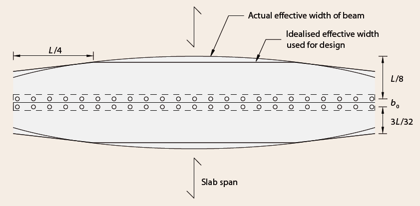
Determination of effective section of concrete portion (effective width)
The first step in defining a composite beam cross section is to access the width of concrete flange available to act compositely with the steel section. The effective widths are expressed in relation to the span of the beam. The constant value of effective width is taken as L/4.
Determination of effective portion steel section:
When the steel beam under compression, its section will be buckled if it is non-compact or slender. In this case, only effective area is considered in the design. For this, the section needs to be classified into the category viz. Compact/Non-Compact/Slender. 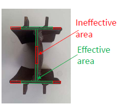
Compact sections are preferred over the non-compact sections. In case if any of the element falls in the category of Non-Compact section, its effective portion needs to be considered in further calculations by calculating reduced widths. For Compact sections, the entire cross section is assumed to be effective without any reductions. Cross section having slender element shall not be used. 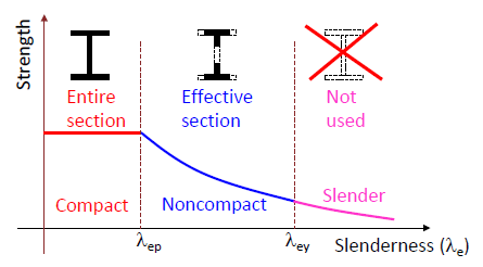
The effective width of steel plate will be determined in accordance with AS4100 which leads to the calculation of element slender ness on account of local buckling. The element slenderness for local buckling shall be checked as follows: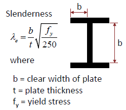
Design of beam for Strength
Designing the composite beam for strength criteria involves calculation of moment capacity. The module is capable of evaluating the sagging moment capacity of a beam as a case of Simply Supported beam.
-
- Moment capacity is calculated considering full shear connection (FSC) i.e. β=1.0
- As a part of FSC, 3 Different cases for the Plastic Neutral Axis (PNA) positioning are considered for evaluation of moment capacity.
- When the concrete slab is stronger than the steel beams, the PNA will lie within the concrete slab as shown in Fig (1). For this case, the ultimate flexural strength is determined from a simple couple force.
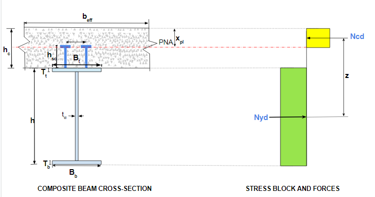 Fig(1) : PNA lies in concrete slab
-
- When the steel beam is stronger than the concrete slab, the plastic neutral axis will lie within the steel beam as shown in Fig (2). For this case, the moment strength can be obtained by summing moments about the centroid of the tension force. There can be two sub-cases in this category viz. PNA lies within top flange of steel beam Fig (2-a)or PNA lies in the web Fig (2-b).

- When the steel beam is stronger than the concrete slab, the plastic neutral axis will lie within the steel beam as shown in Fig (2). For this case, the moment strength can be obtained by summing moments about the centroid of the tension force. There can be two sub-cases in this category viz. PNA lies within top flange of steel beam Fig (2-a)or PNA lies in the web Fig (2-b).
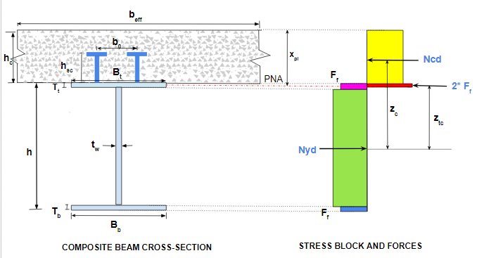
Fig(2-a) : PNA lies in Top Flange of Steel Beam 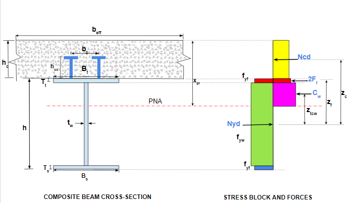 Fig(2-b) : PNA lies in Top Flange of Steel Beam
-
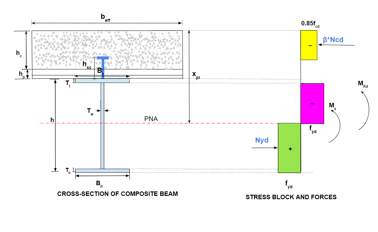
- When there is a corrugated metal deck below the concrete slab, the moment of resistance for FSC is worked out in a similar way considering 3 possibilities of PNA position. The deck orientations are also taken into consideration while evaluating the moment of resistance viz. deck is parallel to span of beam (θ=0), deck is perpendicular to span of beam (θ=90) or any angle made by the decking with beam span in the range of 0 to 90(0<θ<90)
- Further to this, the Moment capacity is calculated considering partial shear connection (PSC) i.e. for value of β=0.1 to 0.9

- The program also estimates the moment capacity of only steel beam section i.e. the case where there is NO COMPOSITE ACTION. This is the case where β=0 and thus, the concrete slab in the cross section does not play any role in the flexure design. This can be the case during construction for a very short duration.
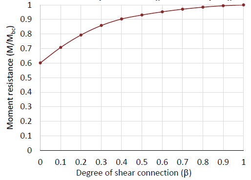
- As prescribed in AS:2327, the relationship between the degree of shear connection β and the moment of resistance ratio (i.e. ratio of moment corresponding to specific value of β to moment corresponding to β=1) for various values of β ranging from 0 to 1.0 are plotted.
- User can get an idea about the moment capacity for certain degree of shear connection for the given cross sectional dimensions and shear connectors. The number of trials for shear connectors in terms of size and spacing can be performed using the program and the graph.
Design of Beam for Shear
-
- Shear check is calculated for vertical shear as well as longitudinal shear.
- Longitudinal shear is evaluated at the interface between concrete slab and steel beam.
- For the given size and spacing (or numbers) of shear connectors, the longitudinal shear carrying capacity is evaluated. Thus, user gets provided value of β for the shear connection. The minimum required value of β is calculated by the program as per Cl. 3.5.8.3. The required value of β for the desired moment of resistance can be obtained from the graph above.
- The above evaluation can guide the user about optimization in case of shear connectors based on the criteria of longitudinal shear resistance.
- The vertical shear resisted by the given cross section is evaluated based on contribution from slab (as per AS2327), structural steel (as per AS4100) and the shear connectors (as per AS2327).
- User can specify whether to consider or ignore the shear contribution from the concrete slab in the shear capacity calculations.
- Two types of shear connectors are supported by the program viz. shear studs and structural bolts.
- The program output provides the intimation to the user about the detailing provisions of shear connectors viz. minimum dia. of connector, minimum and maximum allowed spacing, edge distances, number of rows etc.
Design of Beam for Serviceability
-
- The serviceability calculations involves estimation of deflection under the following cases:
- construction stage (Steel beam only)
- service stage-short term effects (composite section)
- service stage-long term effects due to shrinkage (composite section)
- service stage-long term effects due to creep (composite section)
- The program is capable of calculating the deflection for the above cases based on the theory of either UN-CRACKED section or CRACKED section. The choice is given to the user to specify the section type viz. cracked or un-cracked.
- In case of analysis based on un-cracked section, the transformed area of concrete in terms of structural steel is evaluated by the program and subsequently the other section properties which are needed for deflection calculation.
- Cracked section analysis is based on the assumption that concrete is ignored in the composite section.
- Total deflection is calculated for the above cases which is considered as the permissible deflection for the given cross section and compared with the actual deflection.
- The serviceability calculations involves estimation of deflection under the following cases:
Please watch out this space for the next blog on similar walkthrough for the Composite Columns.