Modeling the beam, supports, and loads in SkyCiv Beam
You can build your model in SkyCiv Beam in a few simple steps. Simply add a beam, specify a cross-section, specify supports, and then apply your loads. You can also optionally add a hinge to your model.
This documentation will cover:
- Defining a beam length
- Adding a section to your beam
- Adding a support to your beam
- Adding point loads to your beam
- Adding distributed loads to your beam
- Adding a hinge to your beam
- Adding load combinations to your model
- Adding a self-weight to your model
- Editing and deleting elements
- Opening your model in S3D
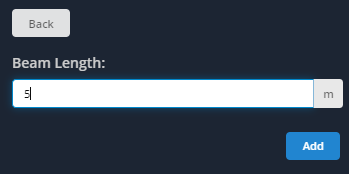
1. Add Beam
Using the left side menu, click the ‘Beam’ button. In the beam length field, enter the length of your beam and click ‘Add’.
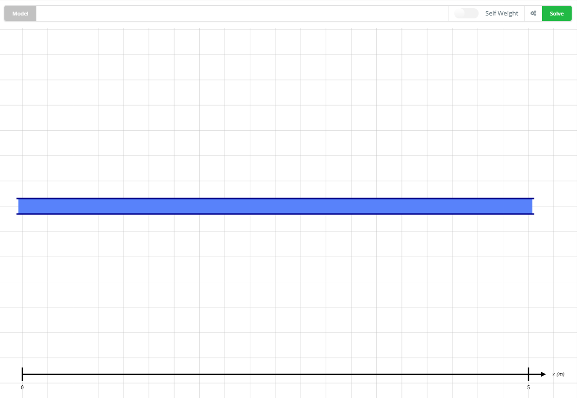
A beam will be added to the screen to the length specified. An X-axis is present to show the length (in this case 5m):
2. Add/Edit Section
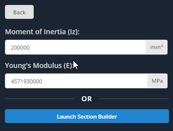
Click the ‘Section’ button on the left to open a panel asking how you’d like to specify your section. There are two options, either use the Section Builder to graphically dimension your section or use a library shape, or input the values for Young’s Modulus (E) and Moment of Inertia (Iz). The next section will cover how to use the Section Builder in detail. For this example, simply input the values as shown in the screenshot. Note that the form fields support scientific notation. Click ‘Back’ when finished.
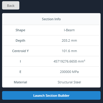
Note that the table to the right will become populated with the beam section information. If the fields for ‘Shape’, ‘Depth’, ‘Centroid Y’, and ‘Material’ show ‘N/A’ this is because the Section Builder was not used.
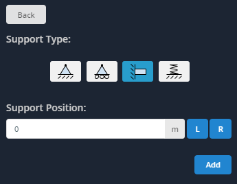
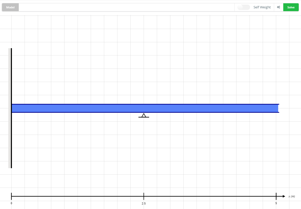
3. Add Support
Click the ‘Supports’ button on the left menu to bring up a panel asking you to select a support type and where to apply it. There are 4 support types to choose from:
- Pin Support
- Roller Support
- Fixed Support
- Spring Support (Also requires a spring stiffness value)
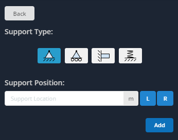
For the support location, this field asks for the distance from the left of the beam to apply the support. You can use the horizontal X-axis as your guide. In this example, apply a ‘Fixed Support’ at the leftmost side of the beam (i.e. at 0 meters). Click ‘Add’ when finished.
Repeat this for a ‘Pin Support’ in the middle of the beam (i.e. at 2.5 meters from the left).
The supports will be added to the screen, as shown below.
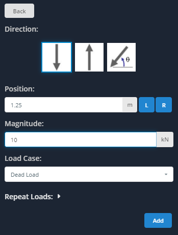
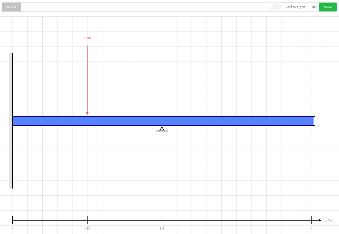
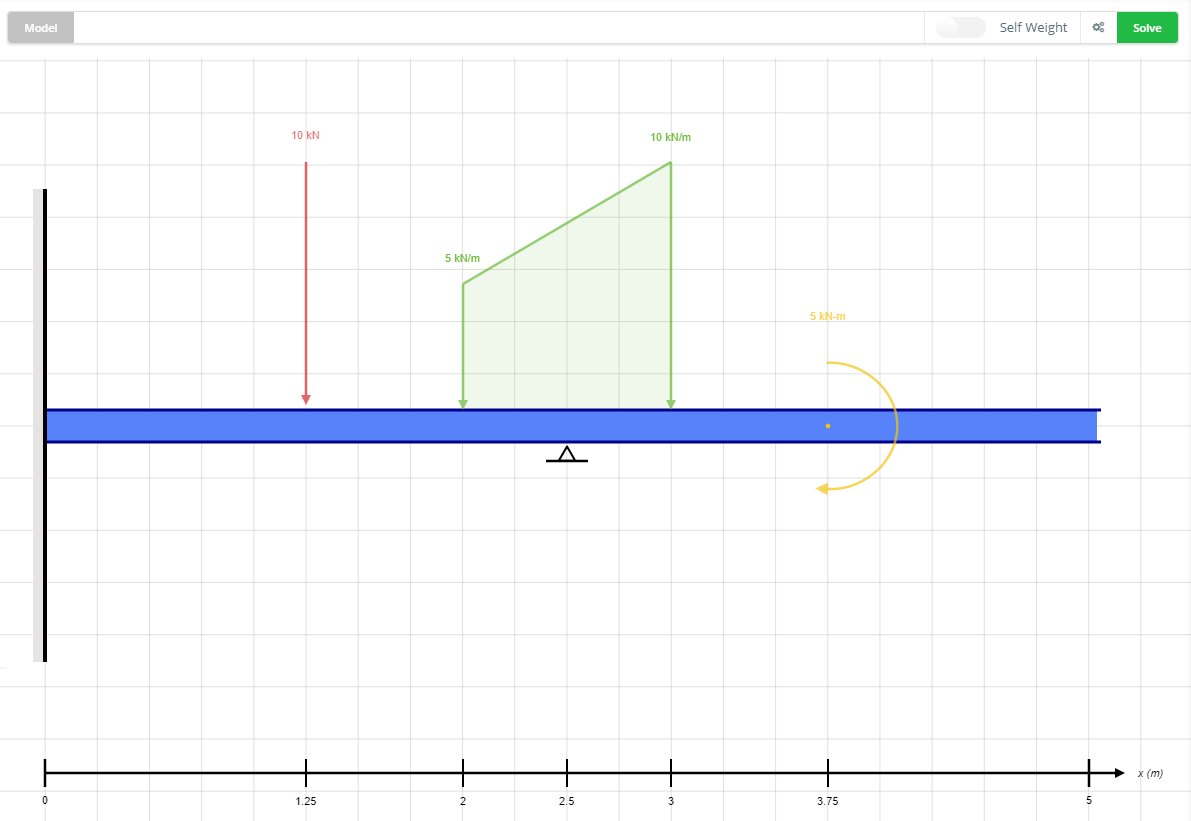
4. Add Point Load
Click the ‘Point Loads’ button on the left to bring up a panel asking you to select a direction, location, and magnitude for your point load. In this example, apply a 10 kN point load, pointing down, at 1.25 meters from the left of the beam. Note that magnitudes need to be positive values. The direction arrows will allow you to specify the appropriate direction (down, up, or angled). Click ‘Add’ when finished.
The point load will be added to the screen, as shown below.
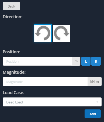
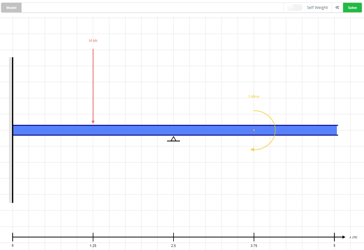
5. Add Moment
Click the ‘Moments’ button on the left to bring up a panel asking you to select a direction, location, and magnitude (similar to specifying a point load). In this example, apply a 5 kN.m moment at 3.75 m along the beam in a counter-clockwise direction. Again, note that values must be entered as positives. Click ‘Add’ when finished.
The moment will be added to the screen, as shown below.
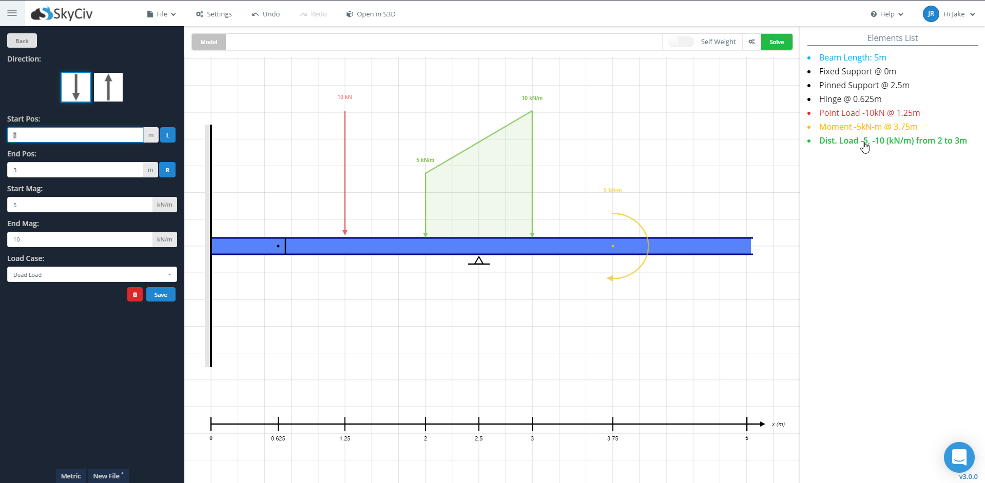
6. Add Distributed Load
Click the ‘Distributed Loads’ button on the left to bring up a panel asking you to select the start and ending values for the loads’ location and magnitude. For this example, specify a non-uniform distributed load between 2 m and 3 m, with magnitudes of 5 kN/m and 10 kN/m, respectively. Click ‘Add’ when finished.
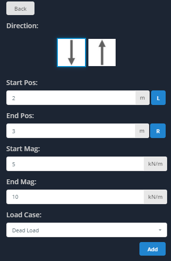
The non-uniform distributed load will be added to the screen, as shown below. A uniform distributed load (UDL) could have been specified by entering in equal magnitudes.
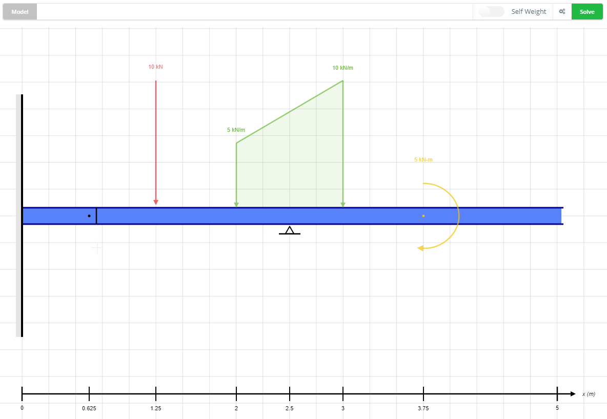
7. Add Hinge (Optional)
Click the ‘Hinges’ button on the left to bring up a panel asking you to specify the hinge’s location within the beam’s midspan. Note that hinges cannot be specified at the endpoints of the beam or at the location of supports. For this example, specify the hinge at 0.625 m from the left. Click ‘Add’ when finished.
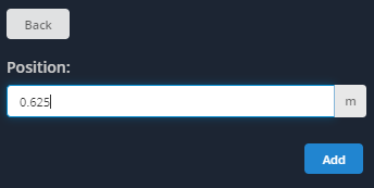
The hinge will be added to the screen, as shown below.
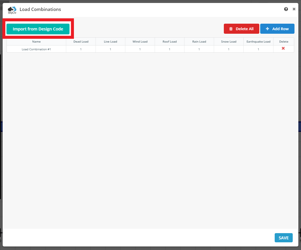
8. Add Load Combinations (Optional)
If you require Load Combinations for your model, click the ‘Load Combinations’ button on the left to bring up the Load Combination Table. From this table, you can define Load Combinations based on the Load Cases listed along the top of the table. Each load can be assigned a load case from the dropdown in the editor.
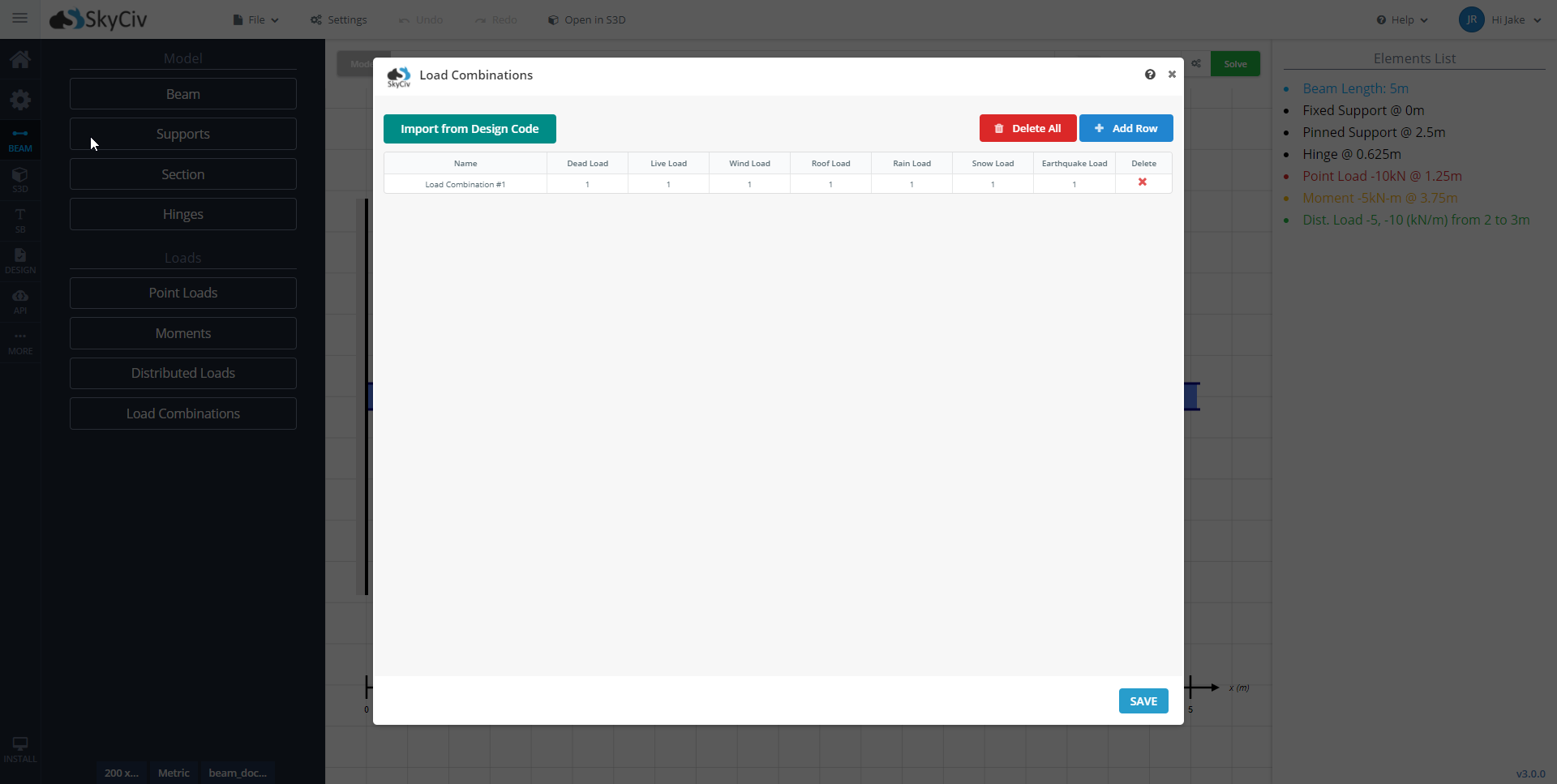
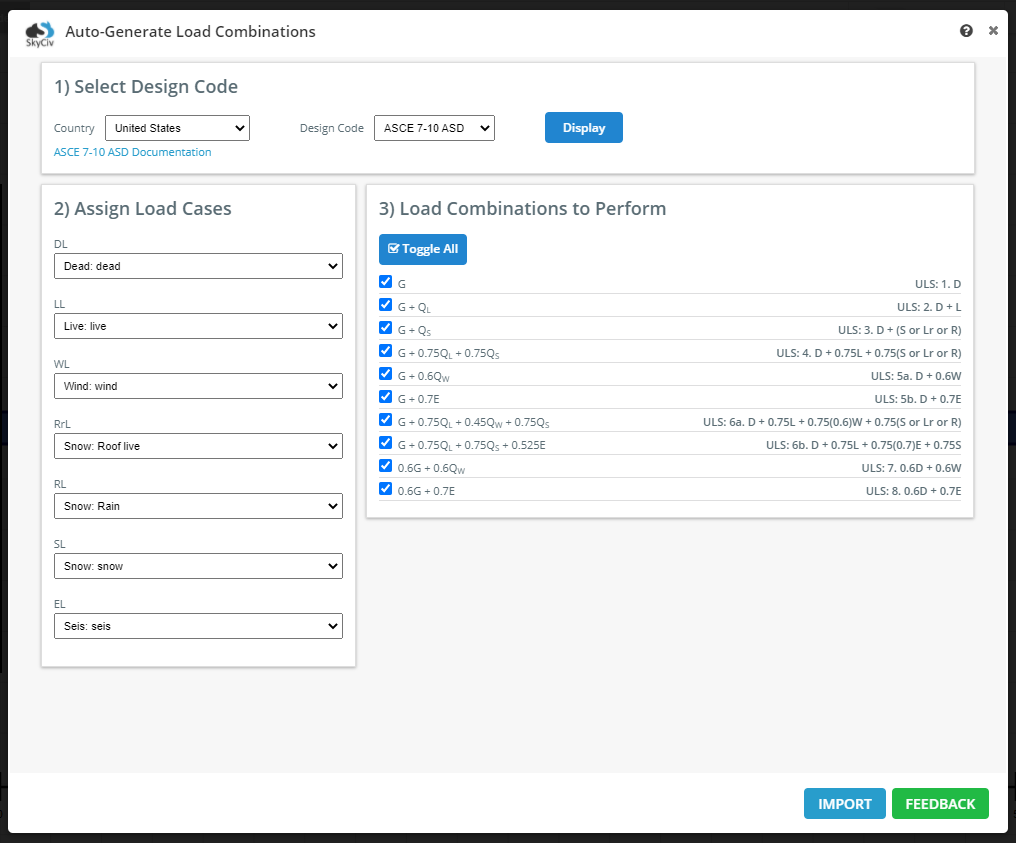
Load Combinations can also be imported from a specified design code. To import Load Combinations, select ‘Import from Design Code’ in the Load Table screen’s top left.
Select the country and the design code from the dropdowns in the Select Design Code box. Click ‘Display’ to generate the load combinations. You can Assign Load Cases and select the Load Combinations to perform. Once you are happy with the Load Combinations, select ‘Import’ to load the combinations into the table.
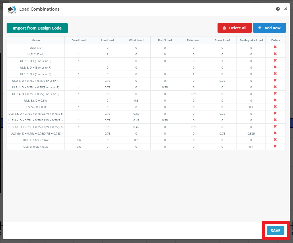
Once you are ready to confirm the Load Combinations in the table, select ‘Save’ to import the combinations into your model.
9. Add A Self Weight (Optional)
A self-weight can be added to your model using the toggle located to your model’s top right. A valid section must be present in the model in order to add a self-weight.
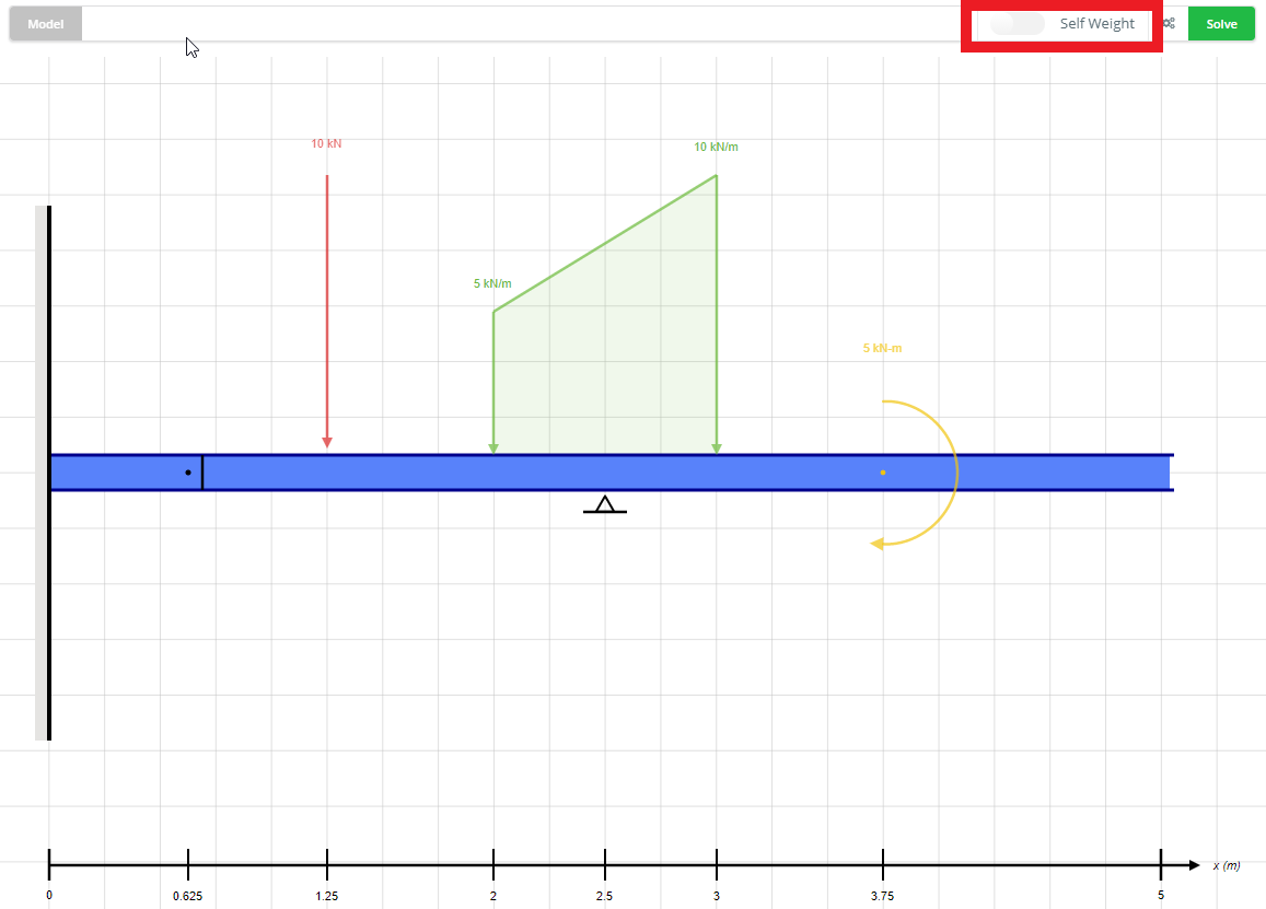
Note: Self Weight is counted as a Dead Load (DL) for Load Combinations
10. Edit and Delete Elements (Optional)
Edits to any of the inputs can be made by selecting the element from the list on the right-side panel. Hover over the element you wish to edit and click to open the element in the editor left side panel element. From the left panel, you can adjust your element using the inputs or delete it using the red delete button in the bottom right of the input field.
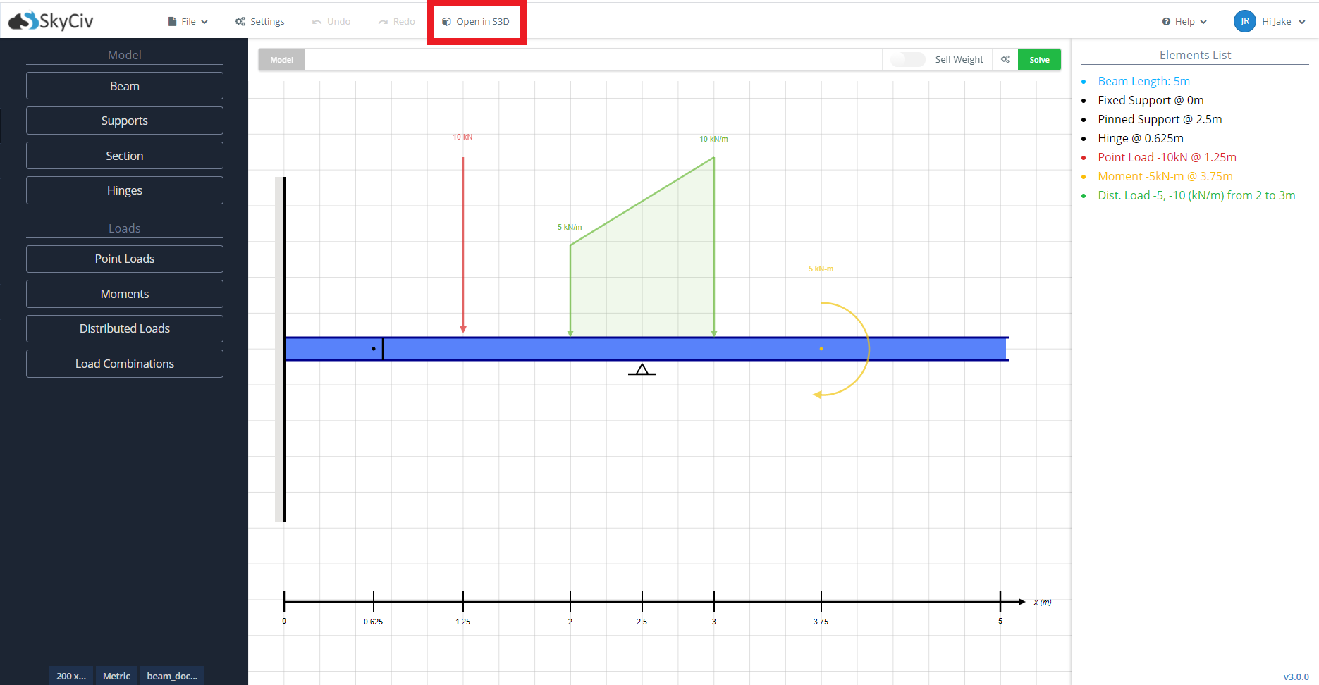
11. Open in S3D (Optional)
If you wish to run your analysis or design in SkyCiv Structural 3D, you can export your beam model from the modeling page. Click the ‘Open in S3D’, and your beam model will be opened as an S3D model in a new tab of your browser. Refer to the S3D Documentation for using this software.
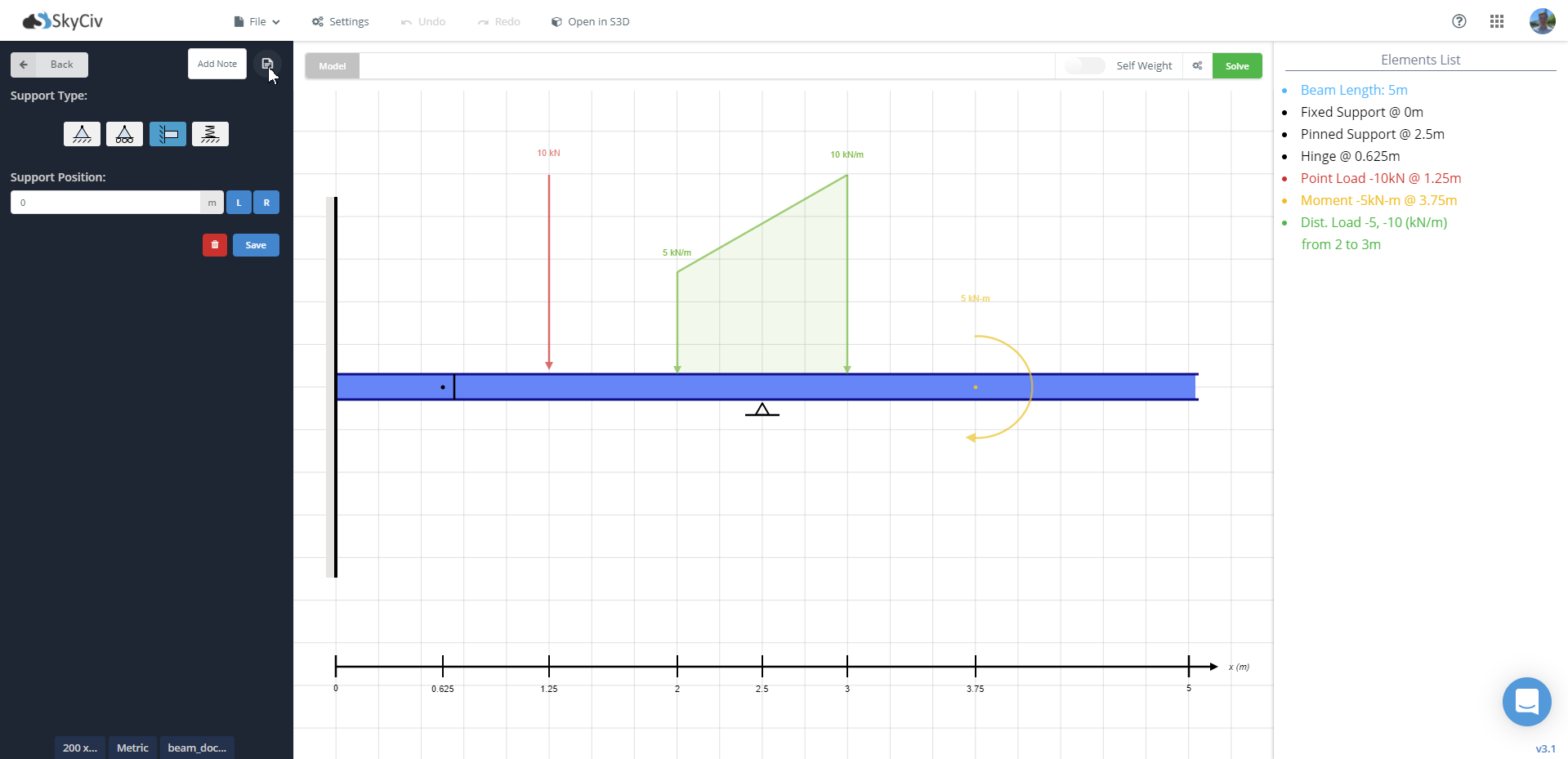
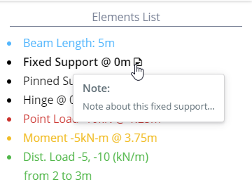
11. Add Notes to Beam Elements (Optional)
You can add notes to your beam model for reference at a later date. Notes can be added to all loads, supports, and hinges in your model. To add a note to a beam element, click on the element on the model diagram or right side ‘Elements List.’ For this example, we will use the fixed support on the left of the beam. Once you have opened the element on the left side input panel, you can find an add note button at the top right.
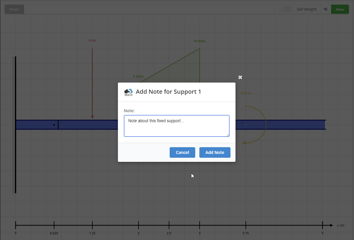
Click this button to bring up the note input for this support. Once you have completed your note click ‘Add Note’. Ensure that you save your model so that your note is saved for future reference.
You will then be able to view your note on the right side ‘Elements List’ via hovering over the note icon. By revisiting the note button, you can edit your note plus view all model notes.
Try Beam Calculator for Free
Still not sure? Try our Free Beam Solver to get a glimpse of what SkyCiv Beam can offer. The tool allows you to calculate reactions, shear force, bending moment, deflection and stress for cantilever or simply supported beams, all for FREE! So test it out now!