Member Design for Timber Structures according to AS 1720 – 2010
General Information
Before you begin
Before you begin the design module, you will need to perform the following extra steps.
- Import design code load combinations.
- Assign design code load cases to the load groups in your model.
Design Specific Information
Current Version Support
Sections
- Rectangular
- Circular
Integrated section database of common sections for sawn timber, GluLam and LVL.
Materials
- Sawn timber, seasoned and unseasoned
- GluLam
- Pole timber
- LVL (coming)
Integrated material database of sawn timber, GluLam and pole timber.
Getting Started
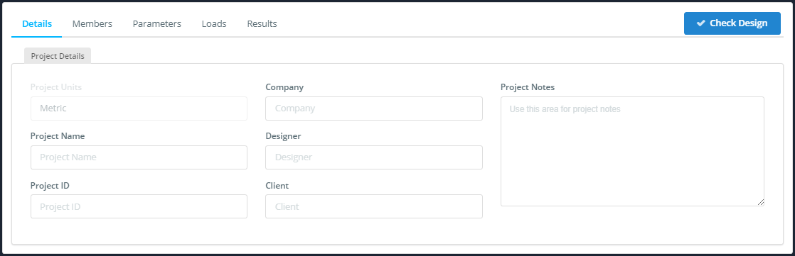
Details
On the Details tab you can enter your project details so that they are displayed on your report, however they are not required.
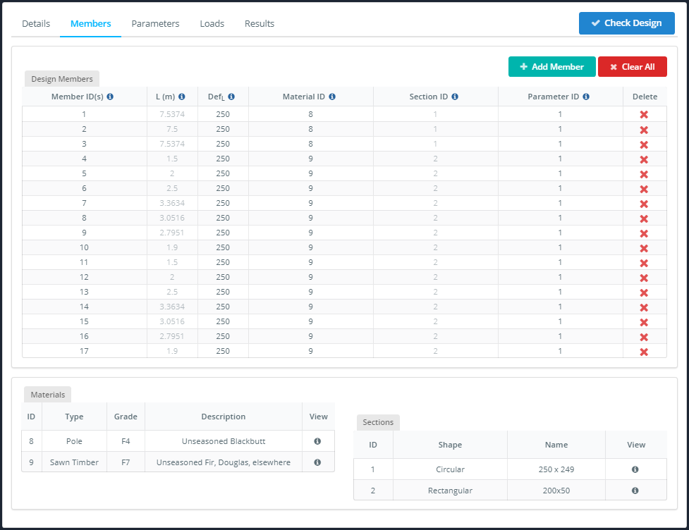
Members
DEFINITION: Design Member: a member, or group of connected members with the same section and material.
The Members tab contains several tables:
- The Design Members table: see below.
- The Materials Table: for your reference to review the materials used in your design.
- The Sections Table: also for reference.
The Design Members table allows you to add, remove and edit the design members deflection limit and parameters. If you are using the S3D integration version this information will be automatically filled with default values.
On the Members tab you can edit:
- The Member ID(s) field: you can add multiple members to a single design member to simplify your design. Enter the member ids separated by commas.
- The DefL field: choose an appropriate deflection limit, this is required for calculating the deflection utility ratio.
- The Parameter ID field: the ID that links your design member to the Parameter table in the Parameters tab, read below for more information about setting parameters.
NOTE: Entering items like members or nodes as a comma separated list is a useful feature used widely in SkyCiv. For example: when modelling you can apply the same loads to multiple members by entering a comma separated list of the member ids in the Member ID field.
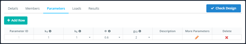
Parameters
Due to the number of parameters required for calculations in AS 1720, we’ve made it easier for you to enter them by creating a parameter table that links to the Design Members table. If you have design members which are similar you don’t need to re-enter the same parameters for each one, just assign them the same Parameter ID.
The Parameter ID is entered in the Design Members table under the Members tab, see above.
NOTE: The bulk of parameters have been hidden – to access them, click the edit icon under More Parameters heading.
On the Parameters tab you can edit:
- The k4 field: partial seasoning factor.
- The k6 drop-down: temperature factor.
- The Φ drop-down: capacity factor.
- The g13 drop-down: effective length factor.
- The Description field: for your reference, does not appear in report.
When the edit icon is clicked is opened, you will see parameters are grouped:
- The Intermediate Restraints tab: for bending and compression buckling.
- The Pole tab: for circular sections.
- The Strength Sharing tab: for bending checks on rectangular sections.
- The Tension tab: for bolted members.
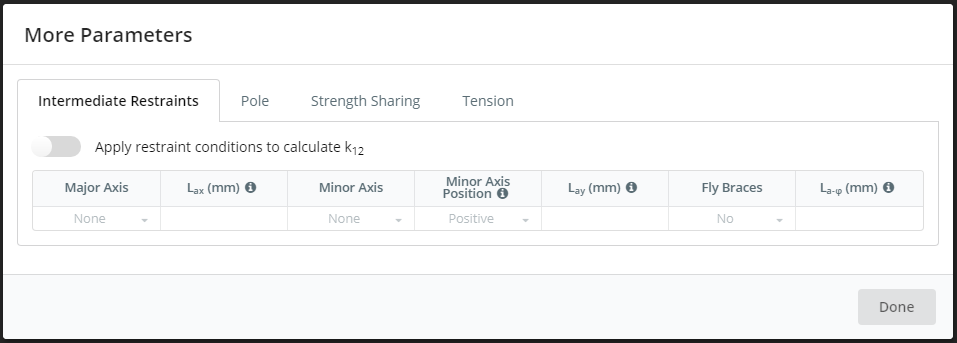
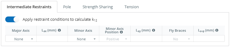
Intermediate Restraints Parameters
If you would like to apply these parameters, please set the Apply toggle to on.
On the Intermediate Restraints tab you can edit:
- The Major Axis drop-down: type of restraint against major axis buckling.
- The Lax field: distance between discrete restraints.
- The Minor Axis drop-down: type of restraint against minor axis buckling and lateral-torsional buckling.
- The Minor Axis Position drop-down position of the restraint on the section, positive if the restraint is on the top edge of a normally orientated beam.
- The Lay field: the distance between discrete restraints, if the Minor Axis field is set to Discrete this is required.
- The Fly Braces drop-down: partial restraint against lateral-torsional buckling.
- The La-φ field: The distance between fly braces.
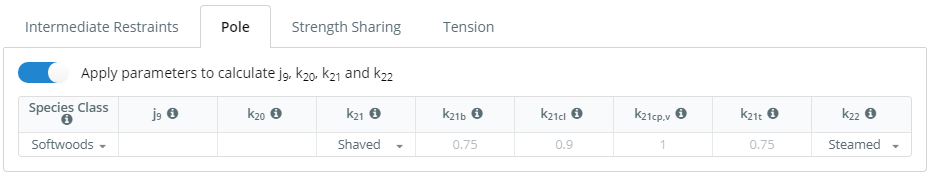
Pole Parameters
If you would like to apply these parameters, please set the Apply toggle to on.
On this tab you can edit:
- The Species Class field: for k20 and k21, the standard provides a method for calculating the values for Eucalypts and Corymbias, and Softwood. Other hardwoods must be estimated.
- The j9 field: immaturity rigidity factor.
- The k20 field: immaturity strength factor.
- The k21 drop-down: shaving factor.
- The k21b, k21cl, k21cp,v, and k21t fields: shaving factors for various strength properties.
- The k22 drop-down: processing type.
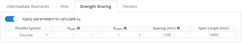
Strength Sharing Parameters
If you would like to apply these parameters, please set the Apply toggle to on.
On the Strength Sharing tab you can edit:
- The Parallel System field: choose a combination of discrete and combined.
- The Ncom drop-down: number of elements combined into a discrete unit.
- The Nmem drop-down: number of discrete units the the system.
- The Spacing field: centre-to-centre spacing of discrete units.
- The Span Length field: effective span of the parallel members.
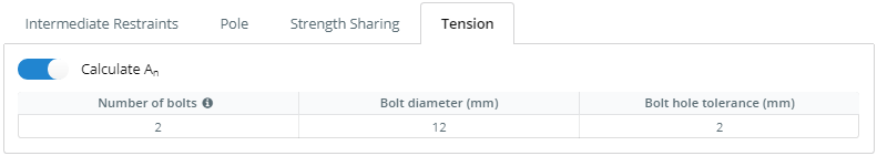
Tension Parameters
If you would like to apply these parameters, please set the Apply toggle to on.
On the Tension tab you can edit:
- The Number of bolts field: number of bolts at the critical cross-section.
- The Bolt diameter field: diameter of the bolts.
- The Bolt hole tolerance field: tolerance.
NOTE: The calculation of An assumes that the bolts are through the smallest cross-section and are evenly spaced. It does not account for minimum spacing or edge distances.
Loads
All materials are affected by creep (slow and minute increases over time of the deformation of an element under continuous load). Timber has a significant creep effect unlike other common construction materials like concrete and steel, timber creep is orders of magnitude more. This makes designing loads on timber structures somewhat more complicated, the duration of load needs to be considered for every load combination.
To account for this effect AS 1720 provides a factor for duration of load for strength (k1) and guidance on the appropriate factors to use for load combinations from AS 1170. These are automatically filled into the load combinations parameters based on the load duration units select.
The Loads tab contains:
- The Strength tab: for strength load combinations.
- The Serviceability tab: for serviceability load combinations.
- The Unallocated tab: user defined load combinations can be moved to either Strength or Serviceability tabs.
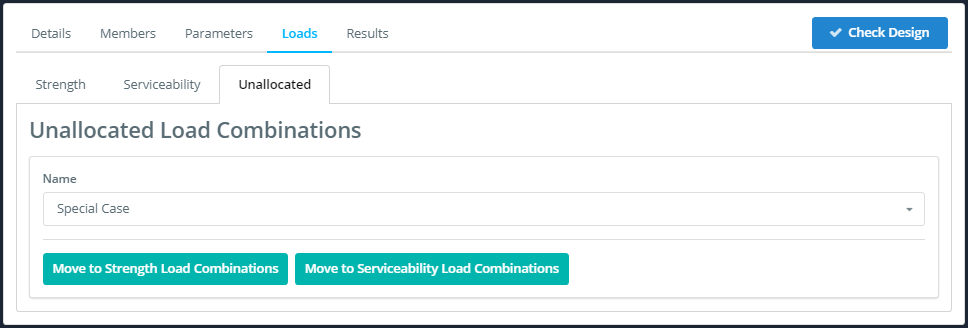
NOTE: To allocate your custom load combinations, simple click the button for the load combination type you’d like to move it to. Afterwards, review the load combination factors in the appropriate tab.
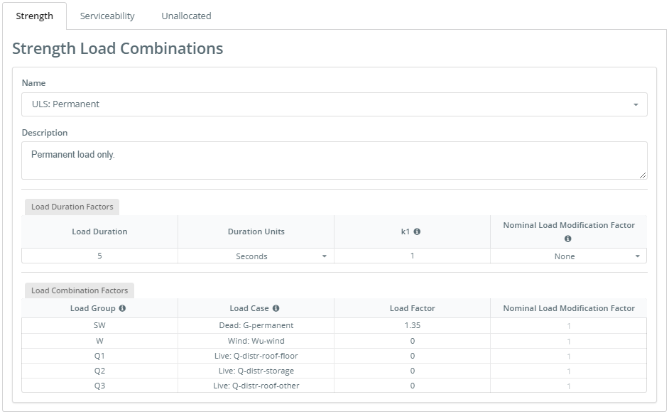
Strength
On the Strength tab you can edit:
- The Name drop-down: select the name of the load combination to be displayed.
- The Description field: for reference, does not appear in report.
- The Duration Units drop-down: seconds, minutes, hours, days, months or decades, these correspond with the k1 factor table.
- The Nominal Load Modification Factor drop-down: none, short-term, long-term, earthquake, combination or custom.
- The Nominal Load Modification Factors fields for each load group: to edit select the ‘custom’ from the Nominal Load Modification Factor drop-down custom type, otherwise these will be automatically filled with AS 1170 values.
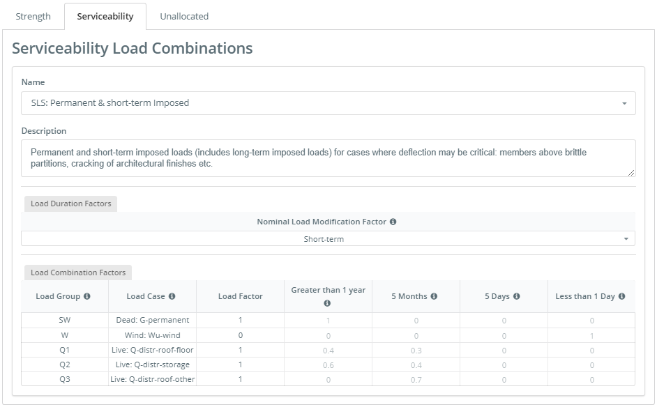
Serviceability
On the Serviceability tab you can edit:
- The Name drop-down: select the name of the load combination to be displayed.
- The Description: not required, does not appear in report.
- The Nominal Load Modification Factor drop down: none, short-term, long-term, earthquake, combination or custom.
- The fields in the Greater than 1 Year, 5 Months, 5 Days and Less then 1 Day columns: these factors are proportions of the load case that is equal to the each respective load duration.
NOTE: Each factor load duration proportion must be ≤ 1 and the sum of all load duration proportions on each row must be ≤ 1.
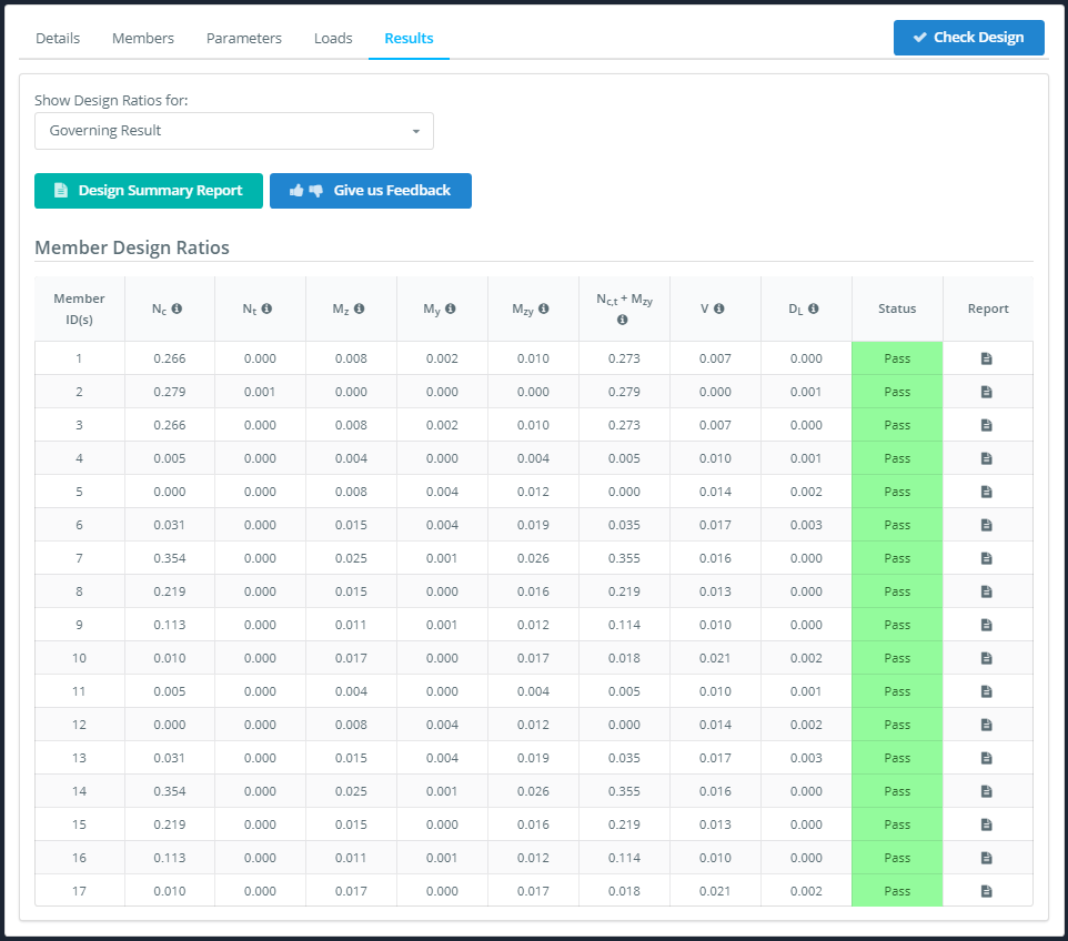
Results
Once you have completed all of the above steps you can now check your design by clicking the Check Design button. The software will alert you if you have missed any required fields, otherwise you will be taken to the Results tab.
In the Results tab you have an overview of the utility ratios of the important checks in the design code in the Member Design Ratios table, if you’d like more detail you can click on the Design Summary button for a summary report.
In this member design module, individual reports are also available by clicking on the report icon in the Report column of the Member Design Ratios table.
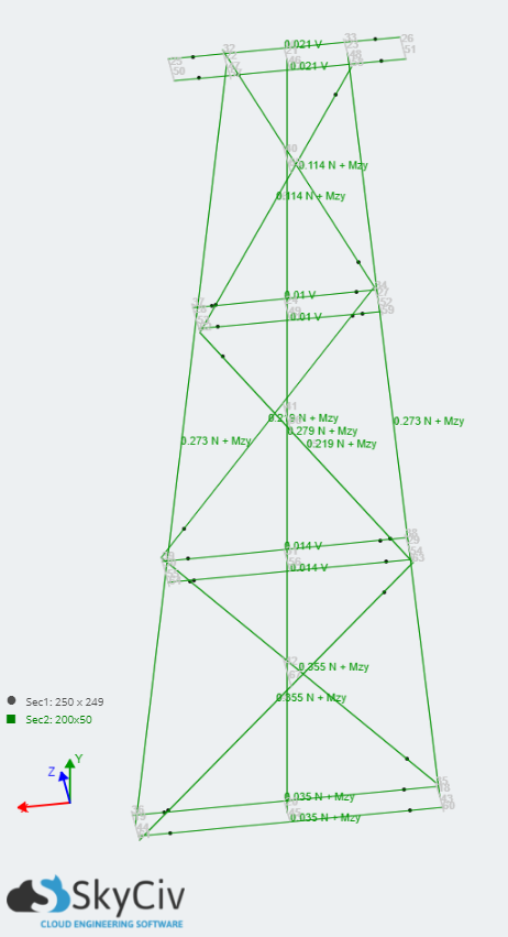
Finally, you can see the overall governing results for each member by checking results displayed on the Wire-frame Model on the left.