A walk-through on how to calculate roof snow loads per ASCE 7-10
The effect of snow loads on a structure can have dire implications if not taken into account during the design period. Procedures and guidelines set out by ASCE in ASCE 7-10 give the structural engineer direction on what these loads are depending on your location in the United States, and how to apply them.
All sections and figures shown or referenced are from ASCE 7-10.
SkyCiv Structural 3D (S3D) gives users the power to load their structures easily and efficiently to meet the design requirements. In this section, we will outline how to calculate snow loads and apply them to your structure, as guided by ASCE 7-10.
We will use Madison, Wisconsin as our example location in the United States to aid in the walk-through of the calculations.
Before we can apply any snow loads to our structure, we need to know the ground snow load at our location, which can be found using Figure 7.1 from ASCE 7-10. In our case, the ground snow load is 30 psf.
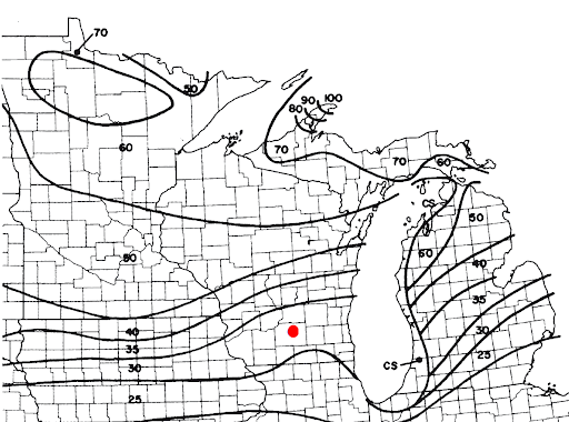
Figure 1: Location of example project in Madison, Wisconsin on Figure 7.1 in ASCE 7-10
In some special cases, site-specific case studies are needed to determine ground snow loads and therefore cannot directly be found on the map provided. See Section 7.2 for more information.
Also, you can directly find the ground snow load for your location through online Hazards by Location tool, provided by ATC.
Flat Roof Snow Loads, \({p}_{f}\)
The snow load that is applied to our structure is not the ground snow load, but in most cases, the flat roof snow load. Other considerations for sloped roofs can be found throughout Chapter 7 of ASCE 7-10. In our case, let’s assume that our structure has a flat roof (roof slope ≤ 5°).
The flat roof snow load is calculated using formula 7.3-1:
\({p}_{f} = 0.7{C}_{e}{C}_{t}{I}_{s}{p}_{g}\)
Where:
\({C}_{e}\) = Exposure Factor
\({C}_{t}\) = Thermal Factor
\({I}_{s}\) = Importance Factor
\({p}_{g}\) = Ground Snow Load
Exposure Factor, \({C}_{e}\)
The exposure factor is determined using Table 7-2 in ASCE 7-10. In our case, the exposure/terrain category for the majority of Madison, Wisconsin is Category B; we will assume that the roof is partially exposed. Therefore, our exposure factor is 0.9.
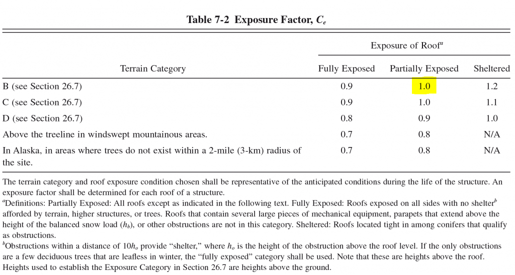
Figure 2: Table 7-2 from ASCE 7-10 with our example case highlighted
Temperature Factor, \({C}_{t}\)
The temperature factor is determined from Table 7-3 in ASCE 7-10. In most cases, the temperature factor is equal to 1.0, which is what we will assume for our case. Other cases can be found below:
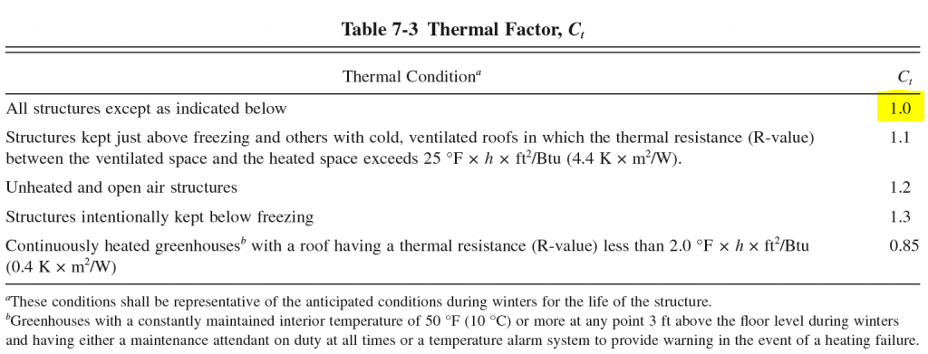
Figure 3: Table 7-3 from ASCE 7-10 with our example case highlighted
Snow Importance Factor, \({I}_{s}\)
The importance factor is something that is not just exclusive to snow load calculations, there are also ice and seismic importance factors as well. To find the snow importance factor for your structure, first find the Risk Category from Table 1.5-1. In our case, we will assume that the Risk Category is Risk Category II, the most common. Next, go to Table 1.5-2 to find the Importance Factor. For this exercise, the snow importance factor is 1.00.
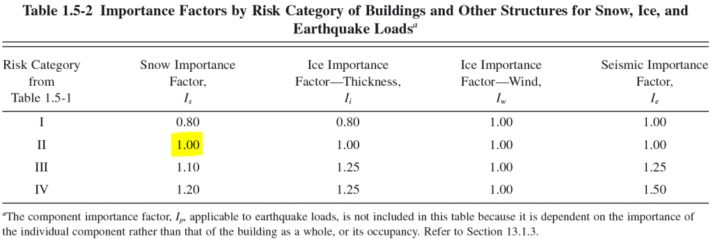
Figure 4: Table 1.5-2 from ASCE 7-10 with our example case highlighted
Using equation 7.3-1, we can now calculate the flat roof snow load for our example location:
\({p}_{f} = 0.7{C}_{e}{C}_{t}{I}_{s}{p}_{g}\)
\({p}_{f} = 0.7*(1.0)*(1.0)*(1.0)*(30 lb/ft^2)\)
\({p}_{f} = 21 lb/ft^2\)
In our case, this is our unfactored, balanced design snow load that will be applied to the structure. The balanced snow load is applied everywhere where the roof structure is located. This includes overhangs and multiple roof levels.
If our structure’s roof was to be sloped, there are additional provisions to find the design snow load. We will explore these below:
Sloped Roof Snow Loads, \({I}_{s}\)
When the roof slope is greater than 5°, the roof is considered sloped. Sloped roof snow loads are assumed to be acting on the horizontal projection of the surface.
The sloped roof snow load is calculated using equation 7.4-1:
\({p}_{s} = {C}_{s}{p}_{f}\)
Where:
\({C}_{s}\) = Roof Slope Factor
\({p}_{f}\) = Flat Roof Snow Load
Roof Slope Factor, \({C}_{s}\)
The roof slope factor is dependent on various roof properties including temperature, shape and material. The roof slope factor can be determined through Sections 7.4.1 through 7.4.4 of ASCE 7-10 and can be known as:
Warm Roof Slope Factor
Cold Roof Slope Factor
Roof Slope Factor for Curved Roofs
Roof Slope Factor for Multiple Folded Plate, Sawtooth, and Barrel Vault Roofs.
Flat Roof Snow Load, \({p}_{f}\)
This is the snow load calculated in the previous section. If your structure has a sloped or flat roof, you still need to calculate the flat roof snow load.
After you obtain the roof slope factor from those sections in ASCE 7-10, the balanced design snow load for the sloped roof can easily be calculated using equation 7.4-1. The balanced snow load is applied everywhere where the roof structure is located. This includes overhangs and multiple roof levels.
Partial, Unbalanced and Drift Loading
In addition to the balanced snow load, certain loading scenarios apply that also need to be taken into account when designing for snow loads on a structure.
Is it the responsibility of the structural engineer to ensure that all possible load cases and combinations possible for a structure are applied and analyzed correctly. Make sure to read carefully through the latter sections of Chapter 7 – Sections 7.5 – 7.12 – of ASCE 7-10 to find any applicable loading additions or conditions in addition to the balanced snow loading condition.
Partial Loading
Partial loading must be applied for continuous beam systems in accordance with Section 7.5-1. Three separate cases must be applied, these cases are illustrated in Figure 7-4. In some cases, the greatest effects on a member are found where only half the balanced snow load is applied. See Section 7.5 for more information.
Unbalanced Snow Loads
Due to the variability of shapes and geometries of roofs, and their interaction with differing wind directions, unbalanced snow loads can differ quite a bit. Different unbalanced loading provisions are present for hip and gable roofs, curved roofs, sawtooth roofs, and dome roofs.
These unbalanced snow loads are analyzed separately from the balanced snow load case, and therefore, are not additive. See Section 7.6 for more information.
Snow Drifts
Roof designs usually present multitudes of roof elevations and rarely offer one single roof height. Because of this, there are roof areas higher and lower than each other and are subject to snow drifts. Snow can either blown from the low side of the roof towards the high side, or is blown off the higher area of the roof onto the lower projected side. The amount of additional snow load, or surcharge, depends on the difference in height of the two adjacent roofs and the lengths of roof perpendicular to the drop in height. See Section 7.7 and 7.8 for more information.
References:
- Minimum Design Loads for Buildings and Other Structures. (2013). ASCE/SEI 7-10. American Society of Civil Engineers.