Design of Seismic Resisting Steel Base Plates
Seismic Resisting Steel Base Plates are often used in structural steel construction to resist lateral and vertical loads, and can be found in a variety of applications including bridges, buildings, and other structures.
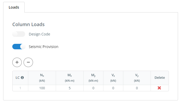
Figure 1 : Seismic Provision when using the User Defined Load Inputs
ACI 318-19 Provision
In ACI 318-19 Section 17.10 all seismic design categories (SDC) C, D, E or F are required to satisfied the additional requirement seismic provision for anchor.
Tensile Provision
-
- if earthquake (strength-level) force is 20 percent not exceeded to the total factor tensile force
- Use tensile strength requirement at section 17.5.2 and 17.6
- if earthquake (strength-level) force is 20 percent exceeded to the total factor tensile force, follow the provision below
- Anchor attachments
- steel strength is taken 1.2 to the nominal strength of the anchor
- if connection are threaded \( f_{uta} / f_{ya} \) shall be at least 1.3 or threaded portions are upset.
- Anchors that resist load reversal shall be protected against buckling
- Anchor shall be designed for the maximum tension obtaining the overstrength factor \( \Omega _{o} \) and calculated in accordance to 17.10.5.4
- The anchor design tensile strength shall be calculates as follows.
- \( \phi N_{sa} \) for a single anchor, or for the most highly stressed individual anchor in an anchor group
- \( 0.75 \phi N_{cb} \) or \( 0.75 \phi N_{cbg} \), except that \( N_{cb} \) or \( N_{cbg} \) need not be calculated if anchor reinforcement satisfying 17.5.2.1(a) is provided
- \( N_{pn} \) for a single anchor or for the most highly stressed individual anchor in an anchor group
- \( 0.75 \phi N_{sb} \) or \( 0.75 \phi N_{sbg} \)
- \( 0.75 \phi N_{a} \) or \( 0.75 \phi N_{ag} \)
- If anchor reinforcement is provided in accordance with 17.5.2.1(a), no reduction in design tensile strength beyond that given in 17.5.2.1 shall be required.
- Anchor attachments
- if earthquake (strength-level) force is 20 percent not exceeded to the total factor tensile force
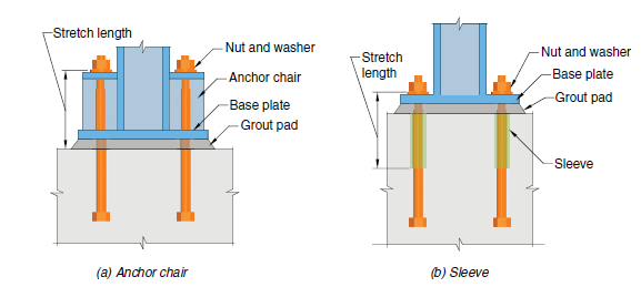
Figure 1: Illustration of strength length (Image obtained in ACI 318-19 Figure R17.10.5.3)
Shear Provision
- if earthquake (strength-level) force is 20 percent not exceeded to the total factor shear force
- tensile strength requirement Section 17.5.2 and 7.6
- if earthquake (strength-level) force is 20 percent exceeded to the total factor shear force, follow the provisions below:
- Anchor attachments
- steel strength is taken 1.2 to the nominal strength of the anchor
- Anchor shall be designed for the maximum tension obtaining the overstrength factor \( \Omega _{o} \) and calculated in accordance to 17.10.5.4
- If anchor reinforcement is provided in accordance with 17.5.2.1(a), no reduction in design tensile strength beyond that given in 17.5.2.1 shall be required.
- Anchor attachments
Tension and Shear Interaction
Single anchors or anchor groups that resist both tensile and shear forces shall be designed in accordance with 17.8, and the anchor design tensile strength calculated in accordance with 17.10.5.4.