A guide on how to apply seismic loads and perform a response spectrum analysis in S3D
What is Response Spectrum Analysis?
Response Spectrum analysis gives users the ability to perform seismic analysis based on the building properties: natural periods, eigenmodes, mass system, and user inputs: load function and load direction.
The Response Spectrum analysis method of earthquake analysis is mainly used in structural design practice and has been established in different design codes such as Eurocode, AASHTO, and ASCE. The basic concept of the method derives from the formula, in which the inertia forces are determined as the sum of mass multiplication on acceleration value and adjusting factors.
The general methodology of Response Spectrum analysis includes the common steps (shown in Figure 1):
- Creating of a Finite Element (FEM) model of the structure with element properties (materials and sections assigned) and boundary conditions
- Adding masses at element nodes (weight/g)
- Defining spectrum load settings and seismic action direction
- Performing frequency analysis; done by applying seismic loads according to eigenmodes and determination of stress-deformed states of the structure at each direction where the load was applied.
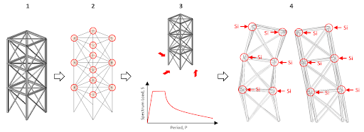
Figure 1: The general sequence of Response Spectrum analysis
After the Response Spectrum Analysis is performed, seismic loads will be generated. Below is the description of the formula for calculation of seismic load at element node \({S}_{i}\)
\({S}_{i}=m \times g \times factors \times \beta \times \eta\)
Where:
\(m=\) member weight related to member node,
\(g=\) acceleration due to gravity (9.806 m/sec^2)
\(factors=\) set of coefficients that adjust earthquake acceleration, surrounding conditions where structure is arranged, soil conditions, etc.
\(\beta=\) dynamic factor that depends on the period of a structure frequency,
\(\eta=\) factor that depends on the relevant eigenmode of the structure.
Applying Seismic Loads (Dynamic Loads)
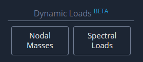
To perform Response Spectrum analysis, users must be operating in SkyCiv Structural 3D (S3D). To begin, users need to apply dynamic loads to their structure. This can be done by going to the left side menu and locating the two buttons, Nodal Masses and Spectral Loads:
Nodal Masses
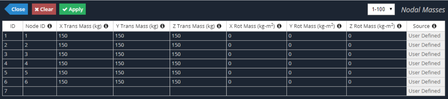
When applying nodal masses, there are two methods that can be used. For the first method, translation and rotational mass values can be directly applied by the user for any node. To do this, click on Nodal Masses as shown above. Here is a look at the input window that users can expect to see:
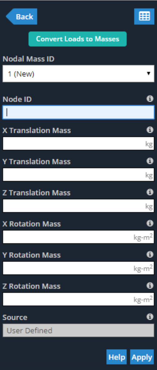
Similar to other inputs throughout Structural 3D, all of these values can be added or adjusted in the Nodal Masses Datasheet, which can be opened by clicking on the datasheet icon shown in the previous figure, or going to Edit > Datasheet Entry > Nodal Masses. Users can expect a similar window to this:
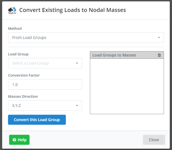
The second method of applying Nodal Masses to a structure in Structural 3D is to convert existing static loads into Nodal Masses. To do this, click on Nodal Masses as shown previously, and then on the Convert Loads to Masses button at the top. This method gives users the power to select a Load Group already applied to their model, input a conversion factor (converted load is multiplied by this factor) and select the action direction of the resultant Nodal Masses. See below for the input window as described:
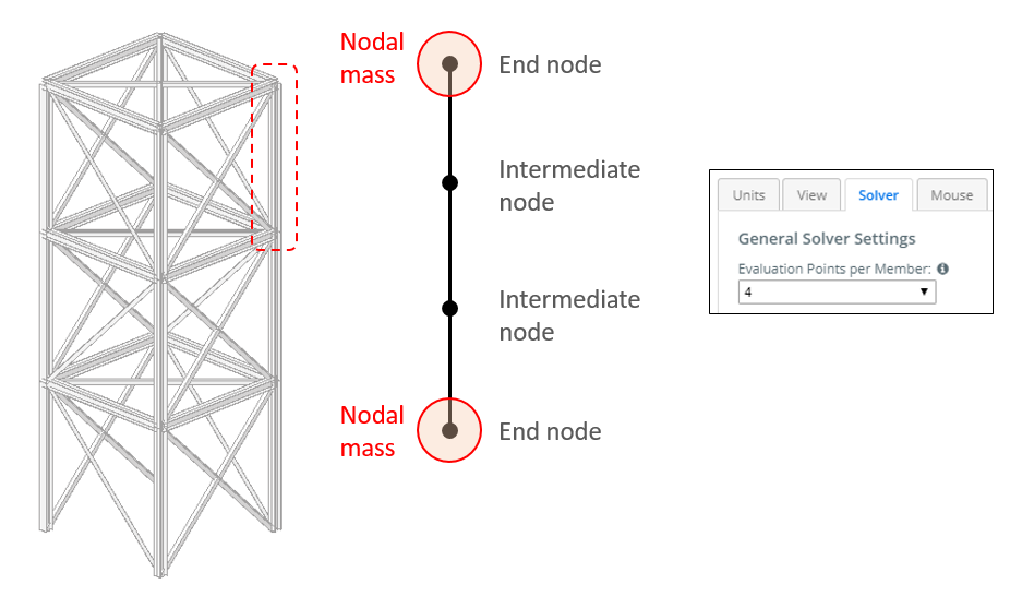
Note, masses can only be applied for the two end nodes of each member or element. Intermediate nodes along the element (evaluation points per member) are mass free. As shown in the figure below, with four evaluation points per each member, the two intermediate evaluation points will not see any Nodal Mass.
At the stage of its release, Nodal Masses can only be applied to members (e.g. beams or columns).
Spectral Loads
To apply Spectral Loads, the Response Spectrum function, seismic force parameters and action direction must be defined. The Response Spectrum function can be defined using one of the two input methods: User Input or Design Code.
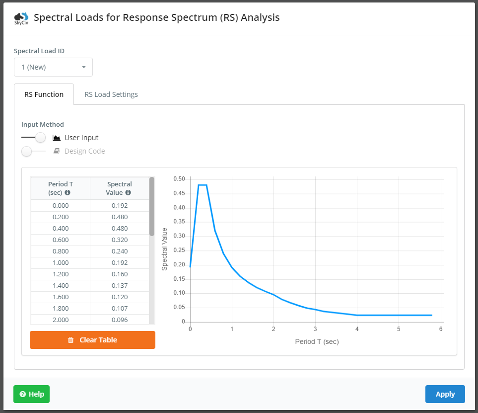
With User Input, users will need to define the Spectrum Data v. Period curve manually and input the corresponding “X” and “Y” values accordingly. Spectrum Data is the normalized acceleration obtained by dividing the acceleration spectrum by the acceleration of gravity. Similar to other data spreadsheets throughout SkyCiv Structural 3D, data can be copied/pasted from MS Excel into the corresponding table (Ctrl + V). Here is an example of the User Input version of the Response Spectrum Function:
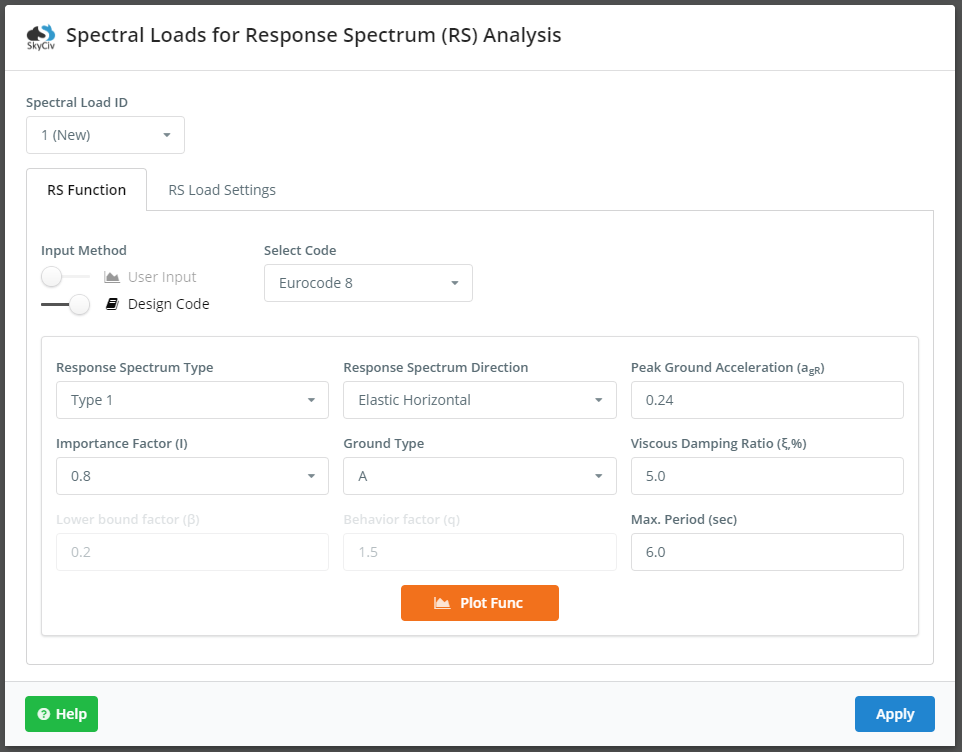
The Design Code method is more common and is commenced by switching the option over to Design Code. This is much simpler as users can easily select their relevant design code and subsequent seismic properties and parameters. After inputting the correct values in their respective fields, the Response Spectrum Function can be automatically generated by clicking the Plot Function button. See below for the relevant inputs for Eurocode 8:
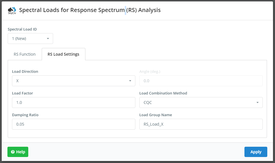
The RS Load Settings tab is where the user will select load direction, load factor, load combination method, damping ratio (in decimal form), and assign a load group name. The defined seismic load is multiplied by the load factor. During the analysis, SkyCiv will combine mode shapes from the dynamic frequency analysis based on the selected load combination method. The load combination methods that are available include:
- SRSS – Square root of the sum of the squares
- CQC – Complete quadratic combination
- ABS – Absolute sum
- Linear – Linear sum
Note, damping ratio is used in the combination method CQC. Here is a look at the RS Load Settings tab and its inputs; these inputs are the same for every design code:
Note, the direction the resultant seismic load can be non-orthogonal to the cardinal directions in the model. To do this, users can select the load direction of XZ. The Angle field will become enabled and users can input the angle they wish. The angle is defined as the angle from the global positive X-axis, as shown: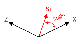

Running the Spectrum Response Analysis and Viewing the Results
It is good practice to define the frequency settings (Top Menu > Settings > Solver) before launching the Response Spectrum Analysis. The section titled Eigenvalue Solver Settings is where users can change these settings, notably the number of Dynamic Modes, as shown: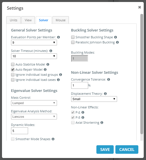
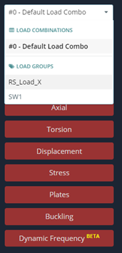
Once the analysis is performed successfully, users can view the analytical results similar to any other load group by selecting the load group from the drop down. The name of the load group will correspond to the name given in Spectral Loads > RS Load Settings. Users can check the maximum stress deformed state of the structure due to seismic action (displacements, reactions, element forces/stresses).
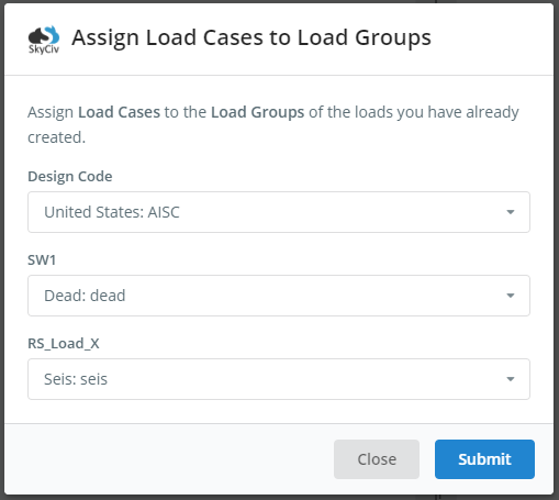
In addition, the Response Spectrum Load Group can be used in Load Combinations similar to any other load case and subsequently analyzed. Users can assign the Response Spectrum Load Group to custom load combinations, or the auto-generated load combinations based on relevant codes offered through SkyCiv. Note, before adding or generating load combinations, users will need to assign the Response Spectrum Load Group to a specific load case (seismic), as shown: