In this section, we will discuss the effects of topography on wind load on structures by calculating the topographic factor Kzt using ASCE 7-16. Speed-up effects due to abrupt changes in topography must be considered in calculating the design wind pressures.
Topographic Factor, Kzt
For ASCE 7-16, section 26.8 details the conditions in calculating the topography factor, Kzt . These are:
- “The hill, ridge, or escarpment is isolated and unobstructed upwind by other similar topographic features of comparable height for 100 times the height of the topographic feature (100H) or 2 mi (3.22 km), whichever is less. This distance shall be measured horizontally from the point at which the height H of the hill, ridge, or escarpment is determined.”
- “The hill, ridge, or escarpment protrudes above the height of upwind terrain features within a 2-mi (3.22-km) radius in any quadrant by a factor of 2 or more.”

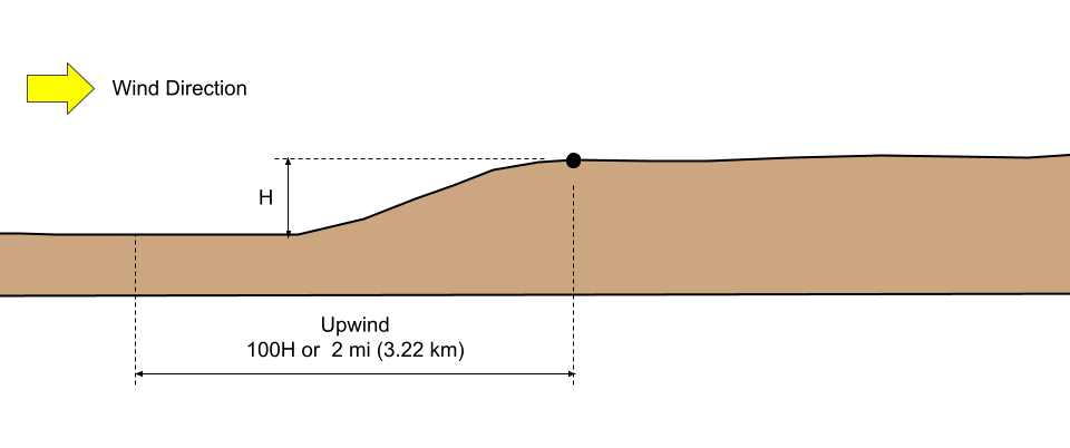
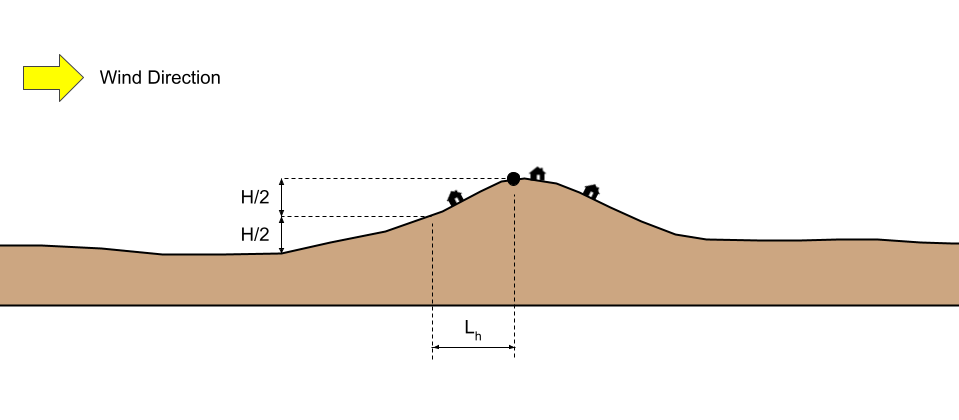
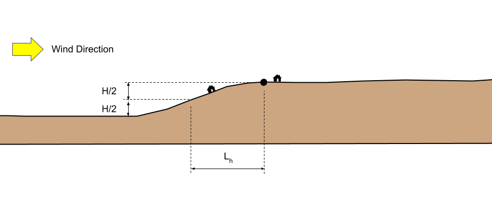
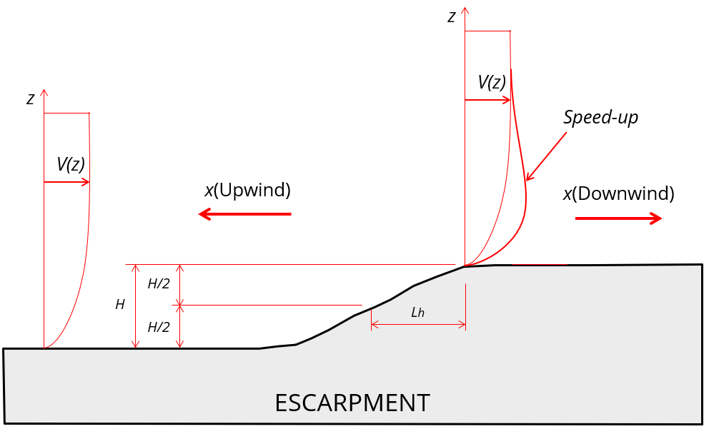
- “The building or other structure is located as shown in Fig. 26.8-1 in the upper one-half of a hill or ridge or near the crest of an escarpment.”
- H/Lh ≥ 0.2
- H is greater than or equal to 15 ft (4.5 m) for Exposure C and D and 60 ft (18 m) for Exposure B.
Where:
H = Height of hill or escarpment relative to the upwind terrain, in ft (m).
Lh = Distance upwind of the crest to where the difference in ground elevation is half the height of hill or escarpment, in ft (m).
Satisfying these conditions, Kzt needs to be considered. Otherwise, Kzt is equal to 1.0.
Case Study
To illustrate the calculation of Kzt, we will consider Gilt Edge Stage Rd, Lewistown, MT 59457, USA (lat: 47.09082818472724, lng:-109.22439642402344) with wind coming from South for our case study in calculating Kzt. The site is classified as Exposure C since there it is an open terrain.
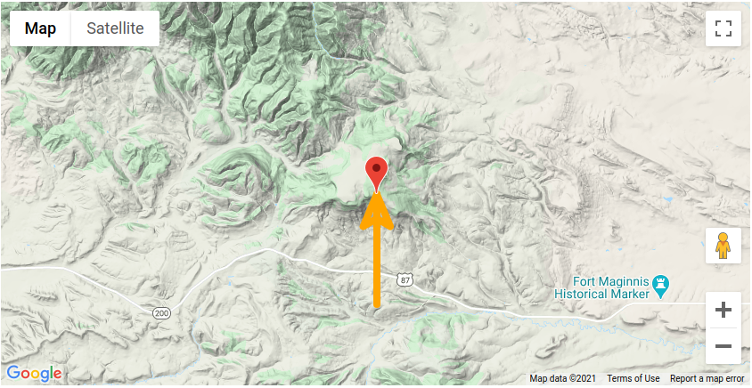

Elevation profile of terrain S-N direction (Google Maps, 2023).
From the map image, we can deduce that the location of the structure is a plateau and can be considered as escarpment due to its flat surface on top. Getting the elevation data from Google Maps and setting the location of the structure as our starting point (negative distance means upwind and positive means downwind location), we can deduce the following points for Figure 26.8-1:
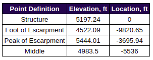
From our date above, we can get H, Lh, and x:
H = 921.02 ft > 60 ft – difference in elevation of peak and foot
Lh = 1842.04 ft – difference of location of peak and location of middle
x = 3695.94 ft – distance of structure to peak of escarpment (negative for upwind, positive for downwind)
H/Lh = 0.501 > 0.2
The topographic factor, Kzt, can be solved using the equation in Figure 26.8-1:
Kzt = (1+K1K2K3)2
K2 = 1 – |x|/μLh
K3 = e−γz/Lh
Where:
K1 = Factor to account for the shape of topographic feature and maximum speed-up effect.
K2 = Factor to account for the reduction in speed-up with distance upwind or downwind of crest.
K3 = Factor to account for the reduction in speed-up with height above local terrain.
x = Distance (upwind or downwind) from the crest to the site of the building or other structure, in ft (m).
z = Height above the ground surface at the site of the building or other structure, in ft (m).
μ = Horizontal attenuation factor.
γ = Height attenuation factor.
For our case study, using Figure 26.8-1, where hill shape is “2D Escarpment.” Moreover, since H/Lh > 0.5, Lh should be equal to 2H:
K1/(H/Lh) = 0.85 (Exposure C)
K1 = 0.425
Lh = 2(921.02) = 1842.04 ft
γ = 2.5
μupwind = 1.5
μdownwind = 4 (adopted due to location of structure)
Since the structure is on the upwind side:
K2 = 1 – |x|/μLh = 1 – |(3695.94)|/(4)(1842.04) = 0.4984
K3 = e-γz/Lh = e-(2.5)z/(1842.04)
Note that K3 varies depending on the elevation from ground of the height being considered. Hence, the corresponding Kzt values per elevation z, are tabulated below:
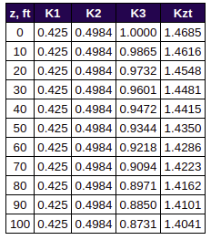
Tabulated values of topo factor Kzt for corresponding z elevation.
It can be observed that as the height above the ground, z, is increasing, the Kzt value is decreasing.
SkyCiv Load Generator
Using the SkyCiv Load Generator, the topography factor Kzt is calculated automatically. All you need to to is put the Project Address, select the Exposure Category and Wind Source Direction and the software will process the elevation data taken from Google Maps.
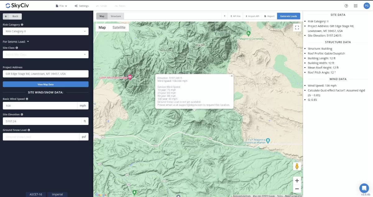
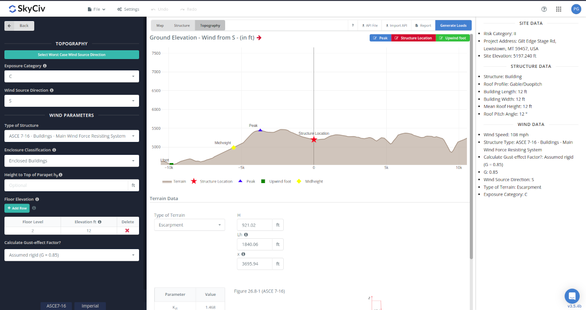
The points for upwind foot, midheight, and peak of the terrain is automatically detected by our software. As the algorithm may not be always accurate, you can overwrite and these values by using the Edit Peak and Edit Upwind Foot buttons for better result of the topo factor. The values on the table are automatically filled up.
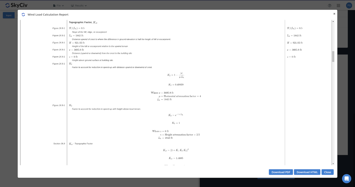
The step-by-step calculation of Kzt that we did above is shown on the detailed wind load calculation of the SkyCiv Load Generator.
Similarly, the topographic/orographic factor can also be calculated in a similar manner for EN 1991, AS/NZS 1170, NBCC 2015, NSCP 2015, and IS 875. Moreover, in SkyCiv Load Generator, the Kzt value used for each level is the conservative value which is calculated at z = 0. Using the Free Wind Load Calculator, you can generate the design wind pressures up to 2 times per day and is limited only to Gable roof profile.
However, the detailed wind load calculation report can only be accessed using a Professional account along with all the full capabilities of SkyCiv modules. The standalone load generator only version can also be purchased thru this link.

Structural Engineer, Product Development
MS Civil Engineering
References:
- Minimum Design Loads for Buildings and Other Structures. (2017). ASCE/SEI 7-16. American Society of Civil Engineers.
- Google Maps