
What is Eccentric Footing?
In some instances, columns lie eccentric to the center of the footing. Footings that are not concentrically loaded are known as “Eccentric Footings”. In addition, when footings are subjected to an axial load “P” and bending moment “M” or lateral force “H”, the footing will experience unbalanced stress distributions along the base of the footing. This can also be achieved with an axial load acting at an eccentricity “e” from the centroid of the footing.
As a result, the total combined stress at the base of the footing is equal to the sum of the stress due to the axial load over footing area (P/A) and the bending moment over section modulus “S” of footing (M/S).
The pressure is assumed to vary linearly, as shown in Figure 1. This distribution is valid where the axial load falls within the kern of the footing area, that is, where the eccentricity “e” is less than L/6. The following equations shown in Figure 1 for soil pressure (q) can be used to determine the minimum and maximum pressures at the extreme edges of the footing¹.
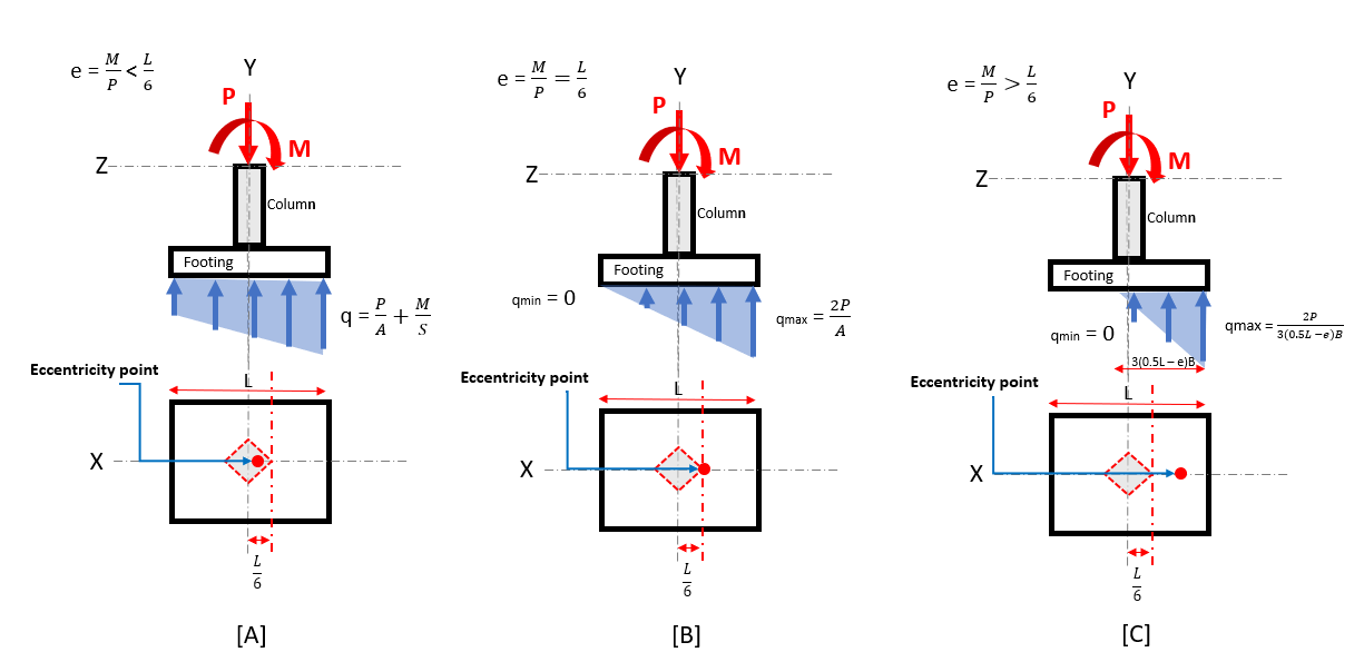
Figure 1. Soil pressure distribution of eccentric footing
(a) eccentric within the kern boundary (b) eccentric within the boundary of the kern (c) eccentric outside the kern boundary
Figure 1A depicts the footing when the eccentricity is located inside of the kern boundary. The entire footing is still in compression and the soil pressure reacts with a trapezoidal distribution where:
qmax = P/A + M/S and qmin = P/A – M/S.
Figure 1B depicts the footing when the eccentricity is located at the kern boundary. The entire footing is still in compression, but the soil pressure now reacts with a triangular distribution where:
qmax = 2P/A.
Figure 1C depicts the footing when the eccentricity is located outside the kern boundary. that when eccentricity is located outside of the kern. The soil pressure still reacts with a triangular distribution, but cannot resist tension (upward movement of footing, or uplift) left of the column boundary. In this case:
qmax = 2P/3(0.5L-e)B
Refer to this link for a more detailed article on soil pressure distribution.
SkyCiv Foundation Design Module
SkyCiv’s Foundation Design Module is integrated with Finite Element Analysis (FEA), delivering more accurate soil pressure analysis and introducing Wood-Armer analysis for detailed flexural design checks.
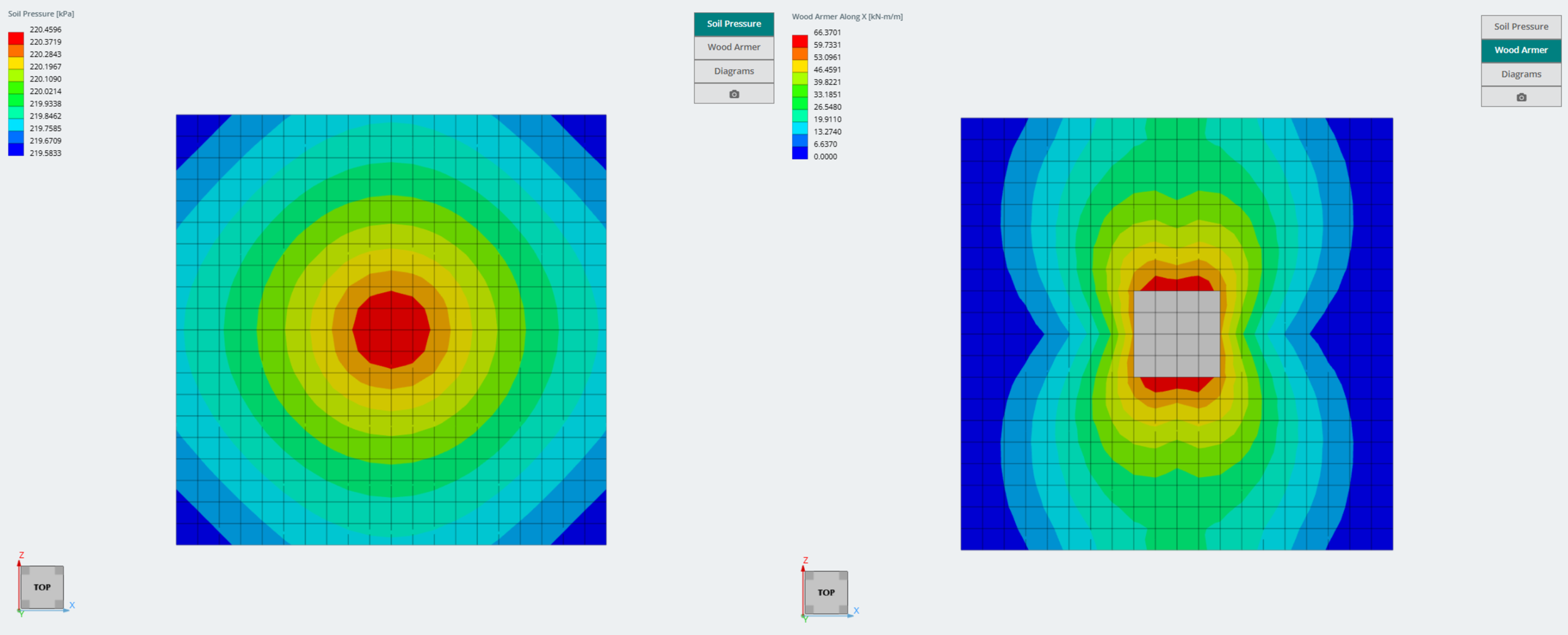
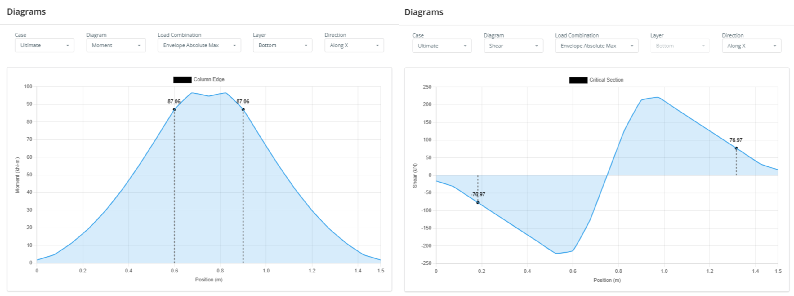
Shear and moment diagrams are also generated directly from the FEA results using the strip average method, providing a clearer picture of internal forces across the footing.
The module supports advanced footing configurations, including column offsets in any direction for both isolated and combined footings. Loads and moments can also be applied in any direction, allowing for accurate modeling of real-world foundation conditions.
Want to try SkyCiv’s Foundation Design software? Our free tool allows users to perform concrete footing calculations without any download or installation!
References
- Reinforced Concrete Structures: Analysis and Design, Second Edition. McGraw-Hill Professional.
