Design of Composite Members as per AS2327: 2017
In this article, we will walk you through various aspects of our Composite Design Module ahead of the release of our new Composite Design Software – a comprehensive solution for analysis and design of composite columns and floor systems.
The module has the capacity to perform design calculations for Composite columns, beams, and slab as per AS2327:2017. The module can be used as a standalone application or as an integrated platform after performing the analysis in Structural 3D.
Features of the Module:
- Design of columns, beams and slabs under SINGLE ROOF as per Strength (ULS) & Serviceability criteria (SLS)
- Multiple beams and columns can be handled and designed at a single run
- The design supports several types of beams and columns are available
- The relationship between the Moment of resistance of a beam and the degree of shear connection can be evaluated graphically in the case of composite beams for full as well as the partial degree of shear connection
- Interaction charts presented in the case of columns as a part of Moment capacity calculations
- Facility to include or exclude the contribution from the slab in moment and shear capacity calculations in the initial and composite stage
- Various orientations of deck profiles ranging from 0 to 90 can be tried as per deck manufacturers’ specifications
- Users can also check the impact on the Moment capacity by introducing various placement positions in terms of flange embedment into a concrete slab.
- Serviceability checks for short-term as well as long-term loading conditions which includes the creep and shrinkage
- Creep time can be as per the user input and can evaluate the deflection calculations can be arrived at various life span of the member
- Longitudinal and transverse shear checks for columns as well as beams
- Combined moment and shear interaction checks for columns and beams
- Covered the database of Australian steel tubes and I shape profiles
- Various environmental conditions viz. arid, interior
Composite Columns:
Composite columns are steel columns whose strength has been enhanced by encasing/filling them with reinforced concrete. They have got a proven earthquake resistance over the ordinary columns.
The module covers 3 types of composite column design viz. Encased, Square/Rectangular Hollow tube filled with concrete and Circular Hollow Tube filled with concrete
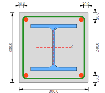
Type-1: I shape Encased in concrete
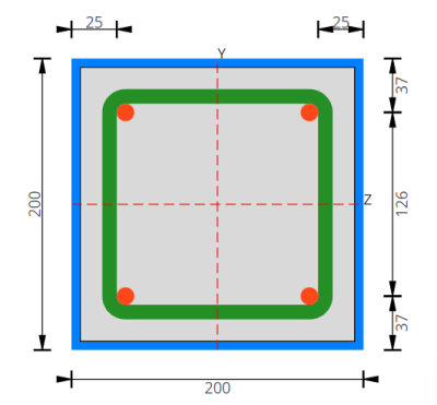 Type-2:Square Hollow Concrete Filled Tube (SHCFT)
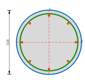
Type-3:Circular Hollow Concrete Filled Tube (CHCFT)
- Concrete Filled Steel Tube columns effectively prevent the inward local buckling of the steel tube resulting in higher local buckling strength than higher hollow steel tubular columns. The lateral pressure in steel tubes induces confining effect in concrete, thus enhancing the strength and ductility.
- Steel contribution factor (Cl. 4.1.1.5)is evaluated as the first thing with which it can be ascertained whether the column with given inputs is going to act as a Composite or Concrete only or Steel Only.
- The program will automatically design the column as a composite column when the steel contribution factor is in the range of 0.2 to 0.9.
- Ultimate design strength checks comprised of the following:
- Axial load capacity-Section resistance (Cl. 4.1.2)
- Axial load capacity-Member resistance (Cl. 4.1.3)
- Shear Strength (Cl. 4.1.2.4)
- Combined axial plus uniaxial bending (Cl. 4.2.2)
- Combined axial plus bi-axial bending (Cl. 4.2.3)
- Longitudinal shear check (Cl. 4.1.2) & EN1994-1-1:2004
- Transverse shear check (Cl. 4.1.2)
- Effect of local buckling is checked as per Cl. 4.1.1.6 for SHCFT & RHCFT
- The detailing provisions are catered by showing the calculations of minimum reinforcement, the minimum required spacing, and bar diameter for longitudinal and shear reinforcement as per Cl.4.3
- The moment capacity calculations are available for the first order as well as the Second order linear elastic analysis. The detailed step-by-step calculation and the interaction diagram for second order analysis as per Cl. 4.5 can be obtained as an output.
- Member imperfections, effective flexural stiffness (EI)eff,II, reduction in the moment capacity because of slenderness/buckling effects, etc. are considered under second-order analysis.
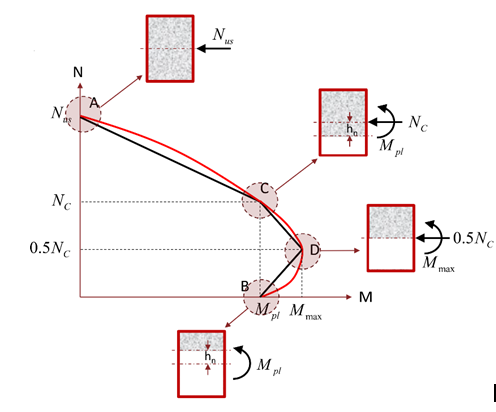
Typical Interaction diagram for Column
- The program evaluates the moment capacity for the major as well as the minor axis of the column and the results are presented in form of an interaction chart.
- The above picture shows the interaction curve for composite columns subjected to combined axial force and bending. For simplification, the curve is replaced by a polygonal diagram defined using certain critical points. These FOUR critical points on the interaction chart are defined and explained below.
- Point A: Axial force only NA = NUS
- Point B: Bending Moment only =Mpl
- Point C:Nc = Acfcd, Mc = Mpl
- Point D: ND = 0.5NC, MD = Mmax
- Following is the sample output for an interaction diagram showing curves for both viz section capacity and member capacity for the trial column section based on the Cl.4.2
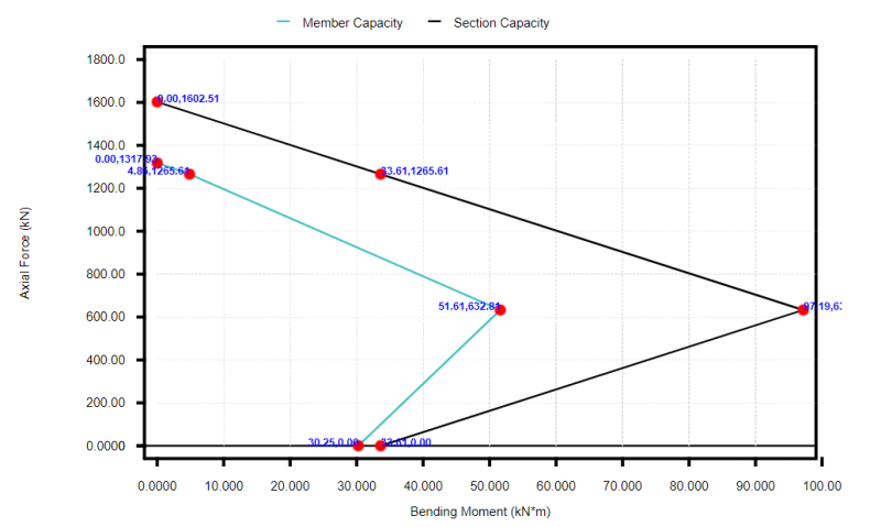
Interaction diagram for Column obtained using the Composite Design module
Composite Beams:
Composite beams are hot rolled sections that compositely act with the slab. The composite interaction is achieved by the attachment of shear connectors welded to the top flange of the steel beam. The shear connectors provide the longitudinal shear connection between the concrete slab and the beam.
The SkyCiv Composite Design Module covers 2 basic types of beams viz. with metal deck and without metal deck:
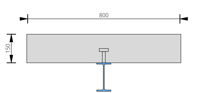
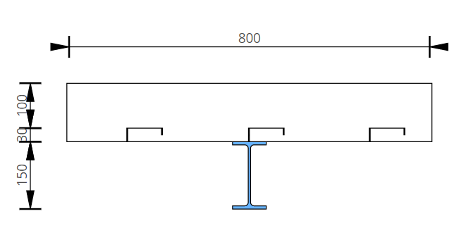
Beam with solid slab (without metal deck)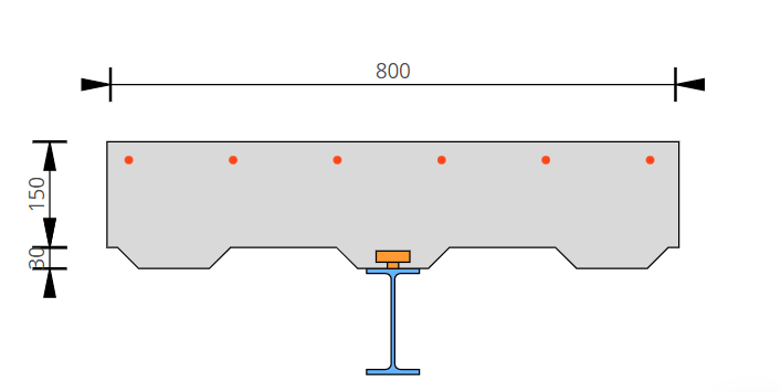
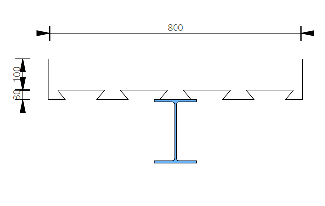
Beam with metal deck
Users can also choose the various types of deck profiles viz. Open trough, Re-entrant and Clipped pan as per requirement. See below:
Beam with open trough type metal deck
Beam with clipped pan type metal deck
Beam with re-entrant type metal deck
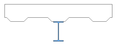
Users can provide any desired orientation for the deck profile i.e. the angle made by the deck ribs with the span of the beam as indicated below. It is an important consideration for composite beam design as the orientation angle (θ) dictates the contribution of concrete in the shaded area for the estimation of the effective depth of the slab. Ultimately, the Moment of resistance calculations is governed by the deck orientation angle. When the orientation angle is in the range of 0<θ<15, the moment of resistance is calculated based on the overall thickness of concrete i.e. concrete in the rib portion is considered in the calculation. When the orientation angle is in the range of 15<θ<90, the concrete in the rib portion (shaded area as shown in the picture below) is ignored in the calculations.
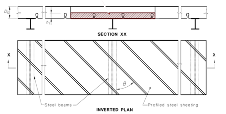
Deck Orientation Angle θ
- The steel beam is checked for slenderness. The program can provide the composite design calculations for COMPACT as well as for NON-COMPACT steel sections. Thus, the reduction in the ‘non-compact’ elements shall be automatically considered by the program after section classification.
- Two types of shear connectors are supported in the module viz. headed studs and structural bolts
- The choice is given to the user to include/exclude the shear resistance offered by the slab along with the beam.
- The contribution of the slab for a shear capacity check is optional and is considered based upon the choice specified by the user.
- Ultimate design strength (ULS) checks comprised of the following:
- Section classification (Plastic/Compact/Slender): Cl.3.4.3
- Design Moment capacity for Full and partial shear connection: Cl. 3.5.4
- Vertical Shear capacity of the slab, steel beam: Cl. 3.5.5
- Longitudinal Shear capacity: Cl. 3.6.3
- Design of Shear Connectors: Cl. 3.6 & Cl. 3.5.8
- Detailing provisions for shear connectors: Cl. 3.6.4
- Combined interaction check for Moment and Shear: Cl. 3.5.6
- Serviceability design (SLS) checks comprised of the following:
- Calculation of shrinkage strain in concrete for a given environmental condition and for a user-specified age of concrete ranging from 1 year to 30 years: Cl.3.1.7, AS3600-2018
- short term deflection of steel beam only (Construction stage): Cl. 3.10.3
- short term deflection of a composite beam under short-term loading for Cracked as well as Un-cracked sections: Cl. 3.10.3
- deflection due to creep: Cl. 3.10.3.3
- long-term deflection due to shrinkage: Cl. 3.10.3.4
- The output of this program provides interaction of Moment capacity (Mrd) of a beam with various degrees of shear connections (β) in a similar format as prescribed in AS2327-Fig-3.5.4.3(B)
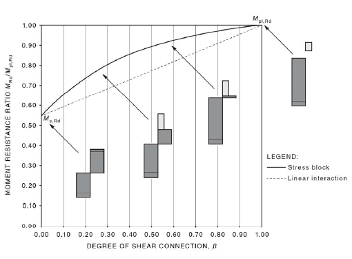
Typical Relationship between Moment of Resistance and degree of shear connection
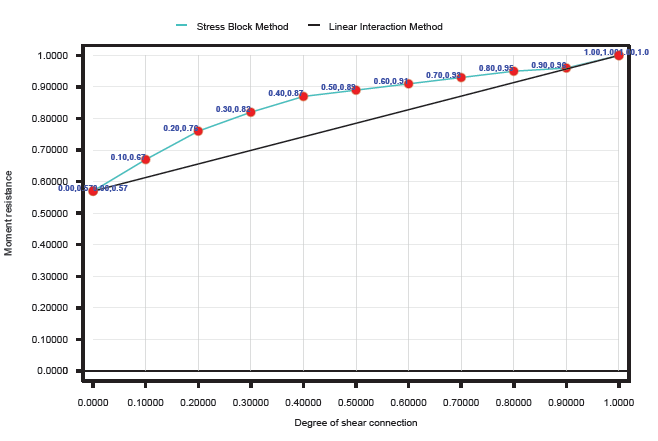
Moment of Resistance Vs Degree of Shear Connection obtained from the Module
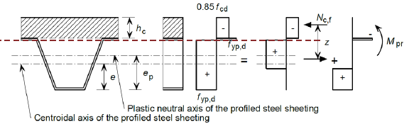
The module can evaluate the various positions of the Plastic Neutral Axis and ultimately the moment of resistance for a case where the top flange is partly embedded into a concrete slab. This is sometimes the practical construction scenario that we have captured and thus the detailed stress block parameters required for estimating Mrd can be obtained in the program output. See the below snapshot for the details.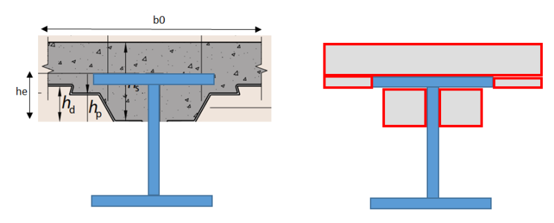
a) A scenario when Beam flange embedded into concrete b) Components considered for stress block calculations
The serviceability calculations are available for either the cracked section or uncracked section as per the user requirements.
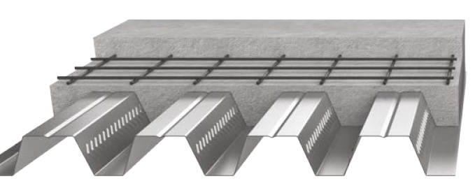
Composite Slabs:
Cast-in-place concrete, reinforcement mesh, and the profiled sheet are the main components that form a composite slab.
The design of a composite slab involves evaluating the capacity of each of these components and verifying its viability by calculating their utilization under a given set of loading.
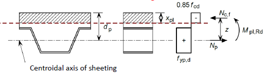
Currently, the program calculates the positive bending in the case of the design of slabs. Two cases in respect of Plastic Neutral Axis (P.N.A) are covered under this category viz. P.N.A. lies in the slab above the sheeting & P.N.A. lies in the sheeting/rib zone. The moment of resistance is calculated based on the position of P.N.A as indicated in the below sketches.
Case-1: Plastic N.A. lies in slab above the sheeting
Case-2: Plastic N.A. lies in the sheeting
- Ultimate design strength (ULS) checks comprised of the following:
- Minimum thickness of slab: Cl.2.2.1
- Moment capacity calculation: Cl.2.7.2
- Vertical shear capacity: Cl. 2.7.4
- Serviceability design (SLS) checks comprised of the following:
- short term deflection of composite slab for Cracked as well as Un-cracked section: Cl. 2.8.3.2
- deflection due to creep: Cl. 2.8.3.3
- long-term deflection due to shrinkage: Cl. 2.8.3.4
Well, it has been a terrific journey for me. Till now, I had the experience of designing each element individually. But, to have it all under ONE roof is a rewarding experience. I hope, you will also feel the same way…
Designing Composite Structures – Sign up to SkyCiv to access the SkyCiv Composite Design Module today!