Lifting Lug Design with SkyCiv Software
What is a Lifting Lug?
A lifting lug is a device attached to the modular part of equipment and structures (for example pressure vessels) that helps to enable these to be lifted, hoisted, and moved around on construction or other industrial sites. Lifting lugs are commonly found on a range of engineering-related equipment including storage tanks, shipping containers, or more specialized operations like piping skids.
What makes up a Lifting Lug?
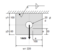
Typical Details of a Lifting Lug
Typically, a lifting lug is made up of a plate or steel section (channel, rod, tube, or hollow section) welded to a main member of the structure that is to be lifted. By welding this plate or section to the object that is to be lifted a strong and secure connection is made between the lifting lug and the main structure.
Given this design, the ultimate force that is induced on a lifting lug is a point load that is applied at any angle depending on factors such as the position, weight, angle, and center of gravity at which the lifting equipment (crane or hoist) applies force to the lug. Due to this the weld that connects the lifting lug to the main structure needs to be designed and checked to the respective action of forces it faces while being lifted to ensure that it can handle these loads without failure.
Welds
Ensuring that the lifting lug is correctly welded is critical to the structural integrity of a lifting lug. When engineering lifting lugs, it is vital to ensure that qualified welders are available to correctly complete the weld with consideration towards quality, penetration, and fusion to prevent failure during lifting. Material selection, compatibility, and size are key to calculate weld capacity and ensuring weld integrity and should always follow industry standards and codes.
Designing a Lifting Lug
With the SkyCiv Lifting Lug Calculator, you can easily check the design of a lifting lug based on length, width & height. When evaluating the capacity of a lifting lug, the following various modes of failure must be checked:
- Tensile Ultimate Resistance
- Tensile Yield Resistance
- Bearing Resistance
- Shear Resistance
- Pin Tear-out Resistance
- Weld Resistance
Using SkyCiv Software to Check for Modes of Failure
SkyCiv Lifting Lug Calculator
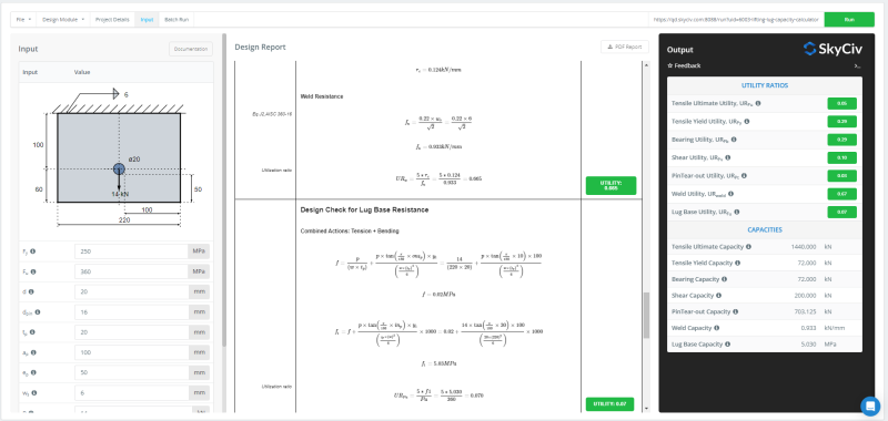
With the SkyCiv Lifting Lug Calculator users can check the design of their lifting lugs per the provisions listed in the AISC 360 ASD method.
To begin users can enter the configuration of the lifting lug and complete the inputs about the lifting pins. The next step is to enter both the in-plane and out-of-plane angle of rotation for the lifting force. The ultimate forces will be calculated after resolving the forces accordingly in the subsequent calculations.
After clicking run, the combined check for tension and shear is provided for the weld. The utilization against all the above checks is provided as a detailed calculation. These calculations are detailed in the design report that lists all the calculations completed during the design check. To view a sample of the software’s design report click here.