Using the SkyCiv Load Generator in ASCE 7 Wind Load Calculation Examples for Open Signs/Frames
To calculate wind load pressures for open signs/frames, the process involves selecting either ASCE 7-16 or ASCE 7-22 as the reference code in SkyCiv Load Generator. Subsequently, the workflow includes defining Site Data, Structure Data, and Wind Load Data.
It’s important to note that access to this wind load calculation feature is limited to paid users. Users with a Professional Account or those who purchase the standalone Load Generator module can benefit from all the features of this calculation for an unlimited duration.
If you’re interested in acquiring the standalone Load Generator module to access these features, you can do so through the following link.
Note that ASCE 7-16 and ASCE 7-22 can be used for Imperial and Metric units. Users will need to define the parameters from top to bottom. The subsequent sections will detail the input parameters that you will need to define to generate the wind results.
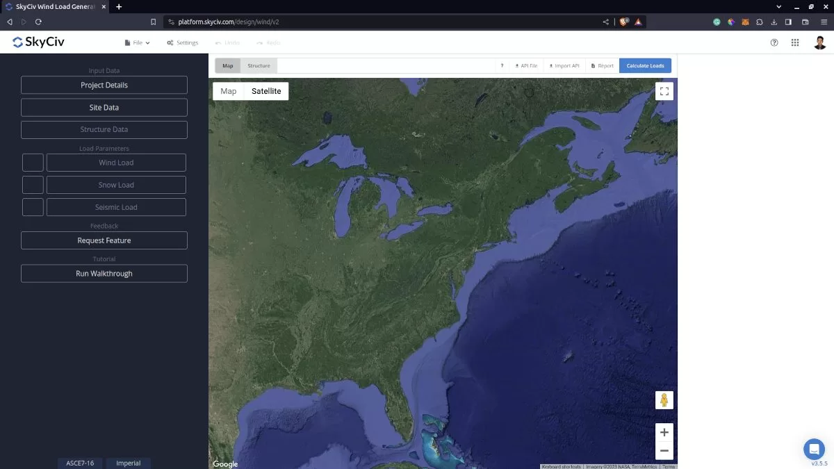
Figure 1. SkyCiv Load Generator UI
Site Data
Users can get the wind speed by location from the SkyCiv wind speed map database. Using ASCE 7, you just need to define the Risk Category of the structure and put the address located in USA, regardless if it is ASCE 7-16 or ASCE 7-22. You can also use the ASCE 7 wind load calculation procedure even if the location is outside USA and its territories. You just need to put the address and manually put the basic wind speed.
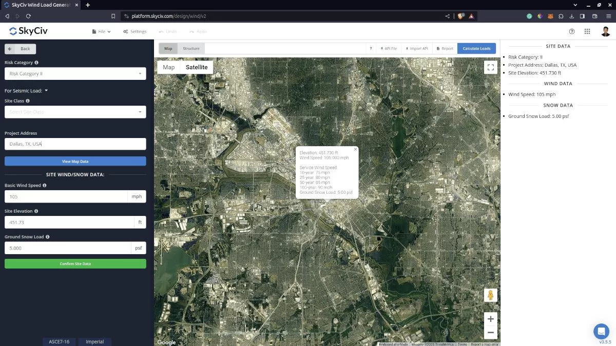
Figure 2. Site data of SkyCiv Load Generator
SkyCiv has digitalized the map as per the paperback standard. This means, you can simply enter in the site location and the software will automatically pull the wind speeds based on this input. There is a limit to how many times the wind speed can be calculated on the free tool. The software will use our internal interpolator to calculate values between the contours, to ensure accurate wind speeds are used in your designs. The Site Elevation is relevant in calculating the Ground Elevation Factor, Ke, for ASCE 7-16 and ASCE 7-22.
Site Input Parameters for Wind Load Calculation
Risk Category – Used in determining the basic wind speed V value
Project Address – Used for getting the nearest wind speed based on the Risk Category selected
Basic Wind Speed – the basic wind speed to be used in calculating the design wind pressure. This is automatically determined based on Risk Category and Project Address and can be modified by the user
Site Elevation – used in calculating the elevation factor Ke (for ASCE 7-16 and ASCE 7-22)
Once the parameters above are completed, we can click the “Confirm Site Data” to check if our input is okay (will change the font color of the button from white to green). After this, we can now proceed to the Structure Data section.
Structure Data
The structure data and the wind and snow parameters are separated into different accordions. In order to calculate design wind pressures, the wind load checkbox should be checked. You need to define first the Structure you are analyzing. Right now, the available structures for ASCE 7 are as follows:
- Building – supports the following roof profile:
- Gable, Hip, Monoslope (enclosed, partially enclosed, or partially open)
- Troughed, Pitched, Open Monoslope (open)
- Truss Tower
- Freestanding Walls/Solid Signs
- Solar Panels
- Ground-mounted
- Rooftop
- Rooftop Equipment/Structure
- Open Signs/Frames
In this documentation, we will focus on Open Signs/Frames.
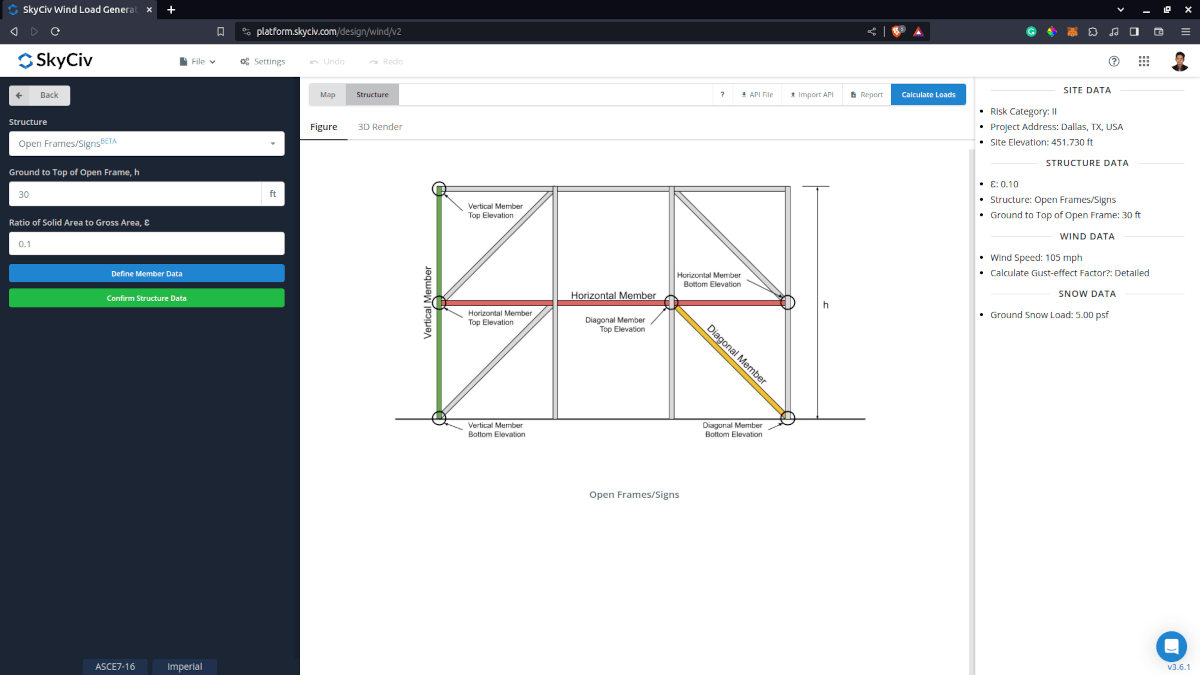
Structure Input Parameters for Wind Load Calculation
Ground to Top of Open Frame – Used in calculating velocity pressure
Ratio of Solid Area to Gross Area– Used in calculation of Net Force Coefficients Cf. Default value is equal to 0.1.
Define Member Data – defining each member data (can be automated in S3D) with the following data:
- Member ID – for determing the element ID especially in S3D
- Section Type – used in calculation of Net Force Coefficients Cf: Flat-sided or Rounded. Default value is Flat-sided when Detect Member Data is used in S3D.
- Section Depth – the dimension of the member perpendicular to the direction of the wind. Default value is the maximum of the section width and depth as assigned in S3D when Detect Member Data is used
- Orientation – options are Vertical, Horizontal, or Diagonal. Automatically detected in S3D.
- Member Bottom Elevation – used in calculating the design wind pressure. Automatically detected in S3D.
- Member Top Elevation – used in calculating the design wind pressure. Automatically detected in S3D.
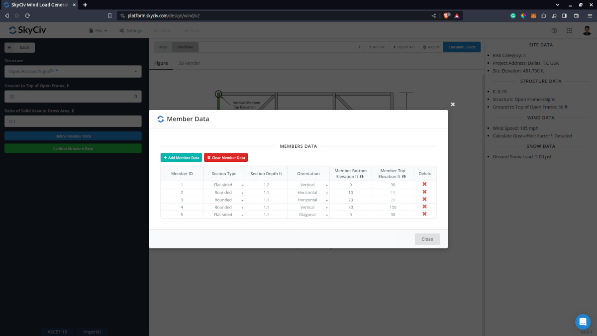
Figure 4. Member data input for open signs/frames.
Once the parameters above are completed and validated (clicking Confirm Structure Data), we can now proceed to the Wind Load Parameters section.
Wind Data
To proceed with our wind load calculation, we need to check the checkbox first beside the Wind Load button. By default, this is checked when the site wind data has been defined.
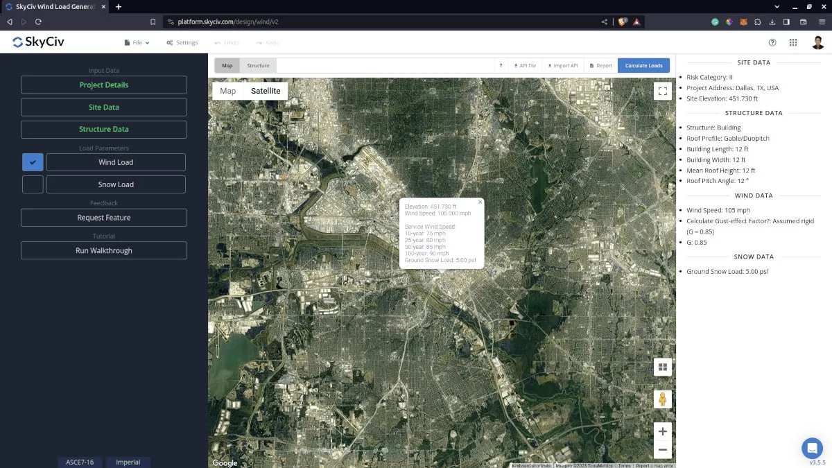
Figure 5. Checkbox for Wind Load Data. The next step, is to define the Wind Source Direction the corresponding Exposure Category of the upwind area.
The Wind Direction parameter is used in obtaining the upwind (left side) and downwind (right side) ground elevations to calculate for Topographic Factor, Kzt. In addition, the Exposure Category is used in determining the Velocity Pressure Coefficient Kz. For standalone users or Professional account, you can determine the worst wind source direction by clicking the View Design Wind Inputs for All Directions button so you can set the Exposure Category per upwind Wind Source Direction as represented by a 45-degree sector. Note that the default Exposure Category is set to Exposure D.
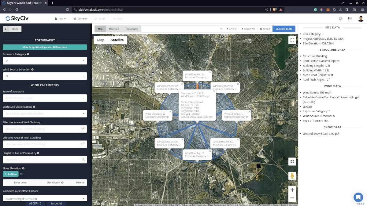
Figure 6. Design Wind Input for all Directions.
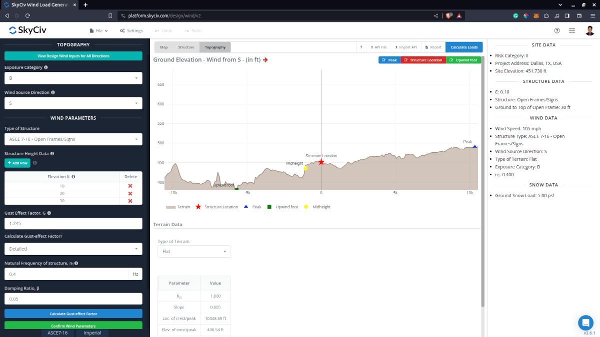
Figure 7. Elevation Data from Google Maps for upwind (left) and downwind side (right).
Topography Input Parameters
Exposure Category – Used in calculation of Velocity Pressure Coefficient Kz and Topographic Factor, Kzt . Assumed to be homogenous for each wind source direction
Wind Source Direction – used to obtain the elevation data on a specific direction section of the area. These elevation data are used in determining the Topographic Factor, Kzt
Type of Terrain – Options to select Flat, Hill, Escarpment, Ridge
H – Height of obstruction/terrain. For type of terrain is set to option other than Flat terrain, this is used in calculating the Topographic Factor, Kzt
Lh – Horizontal distance from peak to the middle height of the obstruction. For type of terrain is set to option other than Flat terrain, this is used in calculating the Topographic Factor, Kzt
x – Horizontal distance of structure to the peak of the obstruction with the peak as the point of reference. For type of terrain is set to option other than Flat terrain, this is used in calculating the Topographic Factor, Kzt
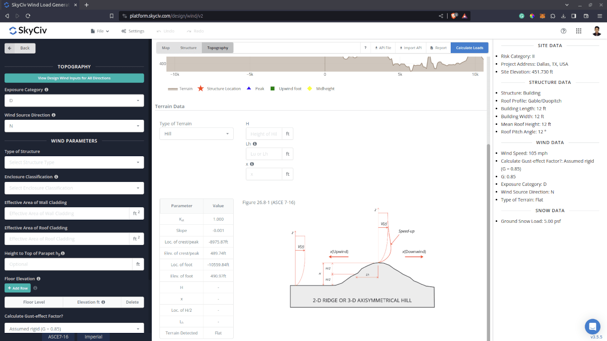
Figure 8. Topography Parameters for ASCE 7.
Wind Input Parameters for MWFRS
Type of Structure – Required to be set to ASCE 7 Open Frames/Signs
Elevation – Since the wind pressure acting on the windward is parabolic in nature, this is used to approximate this pressure by assigning multiple rectangular pressure acting on the structural members in between the level
Gust Effect Factor – Used in calculating the Design Wind Forces. Note: The smallest width of the members is used as B and L in calculating the gust-effect factor. Calculation will be shown in the detailed wind report. Recommended to be edited the user for more appropriate value of the design wind forces
Calculate Gust-effect Factor – Recommended to be set to “Detailed” for calculating the Gust-effect factor for more appropriate value of the design wind forces
Natural Frequency of structure, n1 – Required when detailed Gust-effect factor is selected.
Damping Ratio, β – Required when detailed Gust-effect factor is selected.
Figure 9. Wind Parameters for Open Signs/Frames.
After all these parameters are defined, the next step is to click the Calculate Loads on the upper right side of the UI.
Results
The results of the calculation are shown as follows:
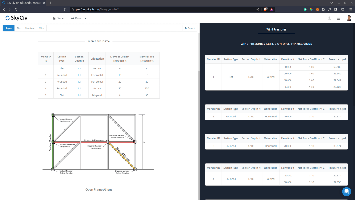
The summarized results are shown on the right side of the screen. Note that the wind results are shown as pressure. These pressure values should be multiplied with the corresponding width of the member and the corresponding length of the load to determine the resultant force.
Detailed Calculation
The detailed wind load calculations can be accessed only by Professional account users and those who purchased the standalone load generator module. All the parameters and assumptions used in the calculation are displayed on the report to make it transparent to the user. You can download a sample detailed calculation thru the following links:
ASCE 7-16 Wind Load for Open Signs/Frames
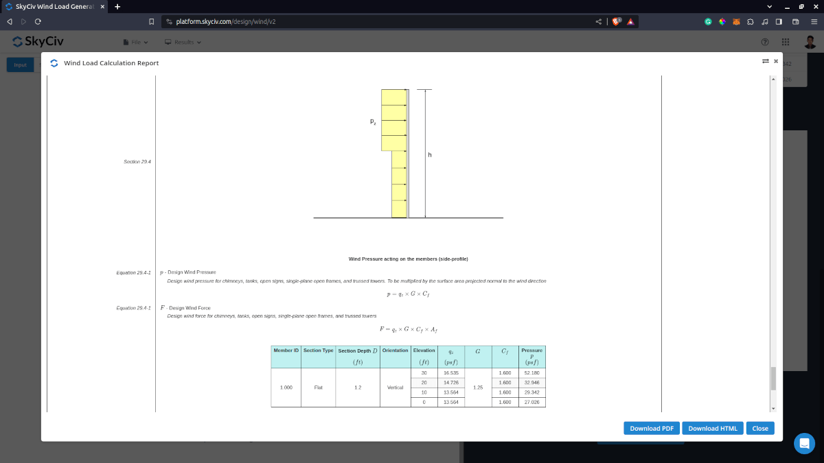
Figure 11. Detailed Wind Load Report for ASCE 7 Open Signs/Frames.
Using In S3D
Using the wind load calculation for open frames in S3D, we will be using the simple scaffolding model in S3D. The model has a round section (Pipe 4XXS) with maximum height of 10m.
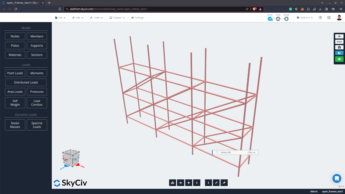
Figure 12. Scaffolding model in S3D with round section.
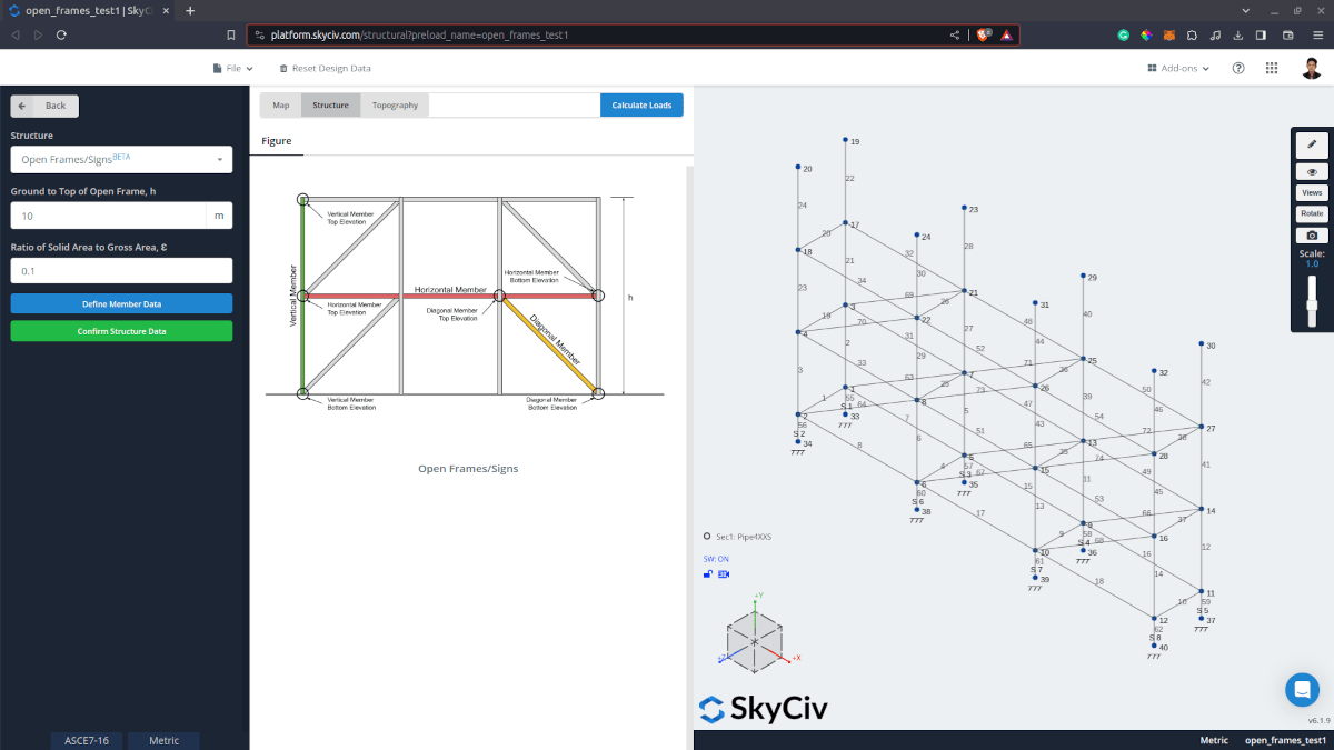
Figure 13. Structure Data input for Open Signs/Frames in S3D.
When defining the member data, you can automatically detect the member data in the model and import it in the Load Generator Input. Take note that the Section Type is set to Flat-type by default and Section Depth equal to the maximum section dimension based on the section assigned. You will need to update these values for each member accordingly.
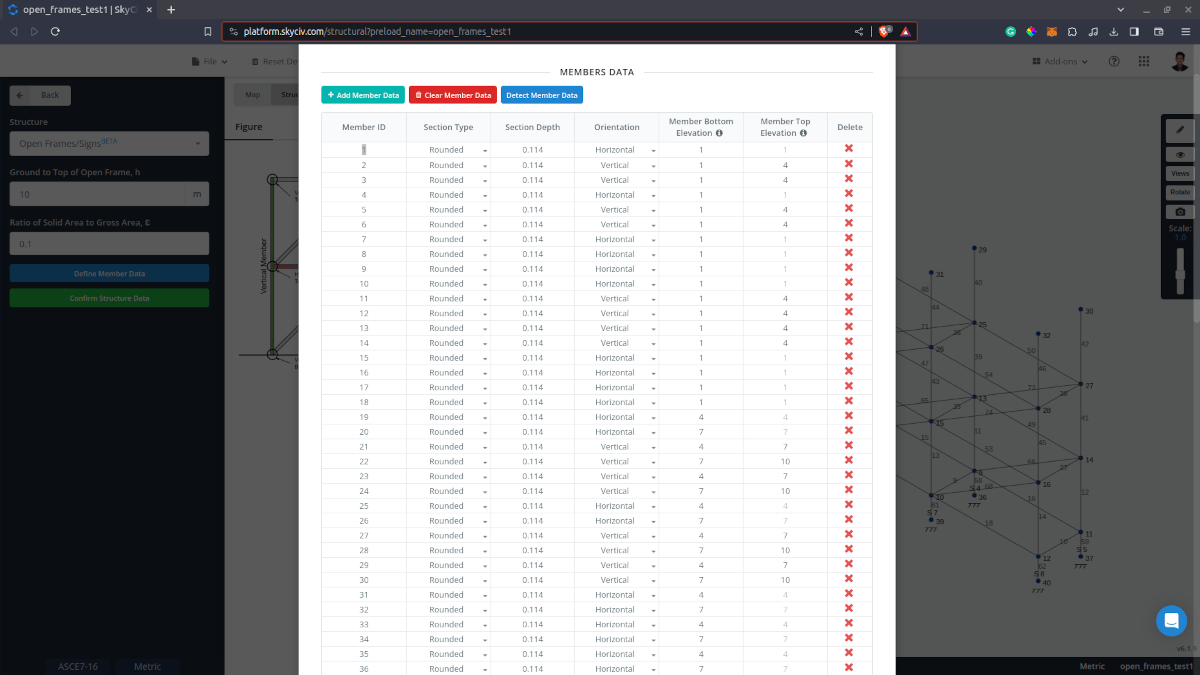
Figure 14. Member Data input detected from the S3D model.
Once the input data are ready, the results will be generated like this:
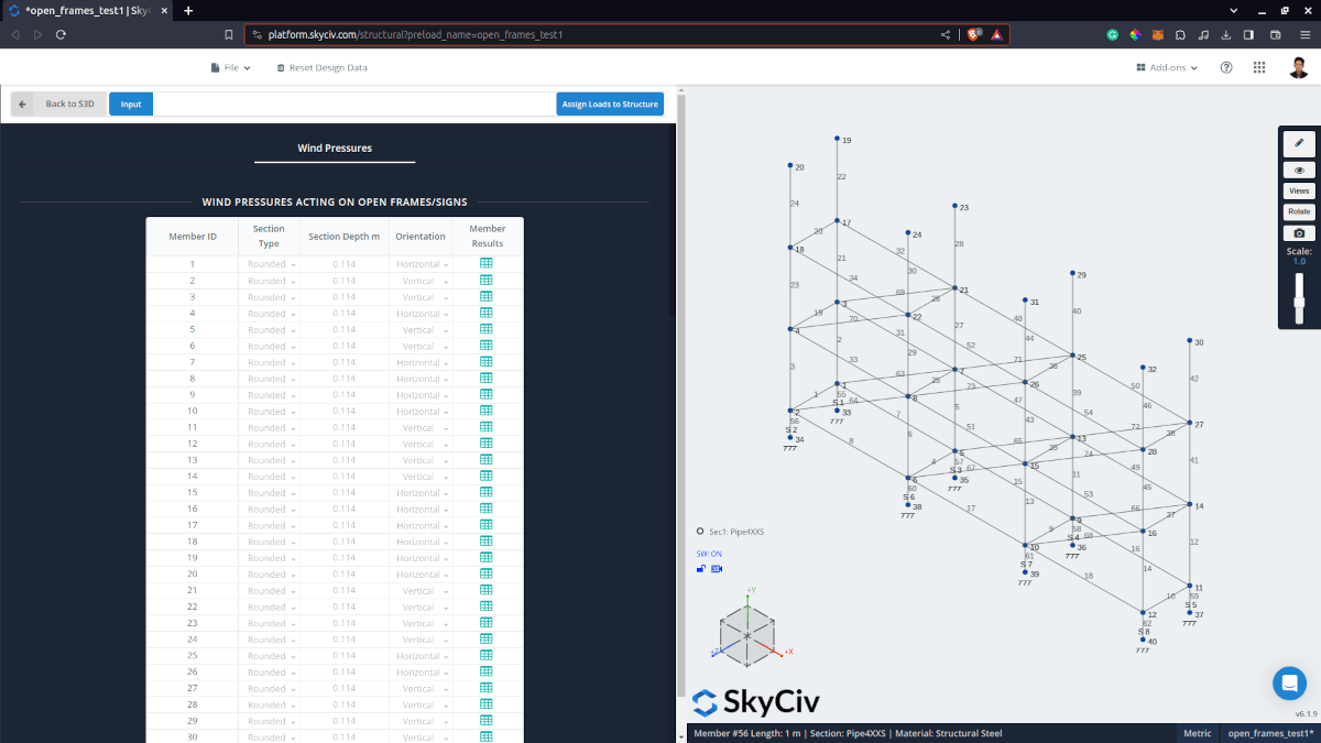
Figure 15. Summarized wind results for each member.
Once all the wind pressures are generated, we can create our load cases for each specified wind direction. For easy input of the member IDs, you can just select the member in the model and then click the Member ID input field. This should automatically import the member IDs of the selected elements in the S3D model. Once ready, you can just click the Commit Loads button to apply the wind pressures to the members. This involves converting the wind pressure calculated for each member into a distributed load applied throughout the member. Note that for ASCE 7, shielding effect is not considered, therefore, the wind pressures applied to the members shall not be reduced.
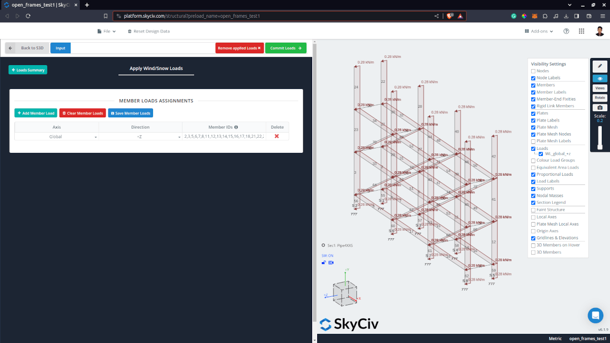
Figure 16. Applied and converted wind pressures to each member in the S3D model.
For additional resources, you can use these links for reference: