The converting and verification of FE models in SkyCiv via API
Nowadays, FEM is the main tool for structural analysis and designing of various types of structures in the world. When creating a FE model of structure the three main approaches can be distinguished. Namely there is a low-level modeling approach, a high-level modeling approach, and the generation of FE models through commands via API.
The low-level modeling approach is based on the step-by-step modeling using FEM software functionality at each modeling step. The FE model is created manually. Engineer manually defines nodes in space, set FE between nodes, set materials, set loads, set boundary conditions, etc. This modeling approach is the main and widely used among engineers.
The high-level approach is based on the special templates in FEM software, which are adapted for certain types of structures. This may be a dialog box in which an engineer input the structural data. Then the software automatically generates a ready-made FE model from this data. This approach may be considered as abstract since an engineer does spend time on the FE model creating.
The third approach is one of the most powerful and flexible in creating FE models of structures. Here the process of FE model creating can be carried out through a script which includes special executing commands.
Use cases of script-based FEM models
This mean that engineer can describe the sequence of FE model auto-generation, analysis, results post-processing using the form of a text. Such a tool gives capabilities in the structure analysis with optimization in comparison with the previous two approaches. Below are the main areas of API application for structural analysis and design:
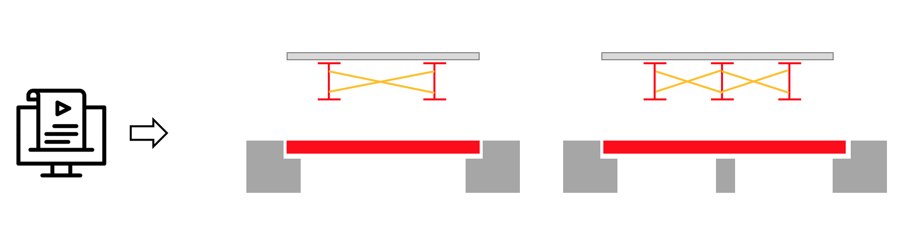
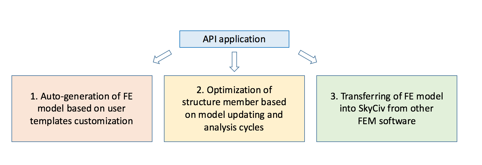 1. Engineer can create a set of their own templates for FE model auto-generation. For example, an engineer is dealing with a section of a highway on which many different bridges of the same type must be located. The bridge structure topology is the same, but only some basic parameters must be changed, such as the road width, the length of spans, the number of main girders and their sizes. Accordingly, through the API, the engineer can create script for auto-generation of many bridge models with the indicated differences between them and perform an analysis with subsequent auto-post-processing of results and member design.
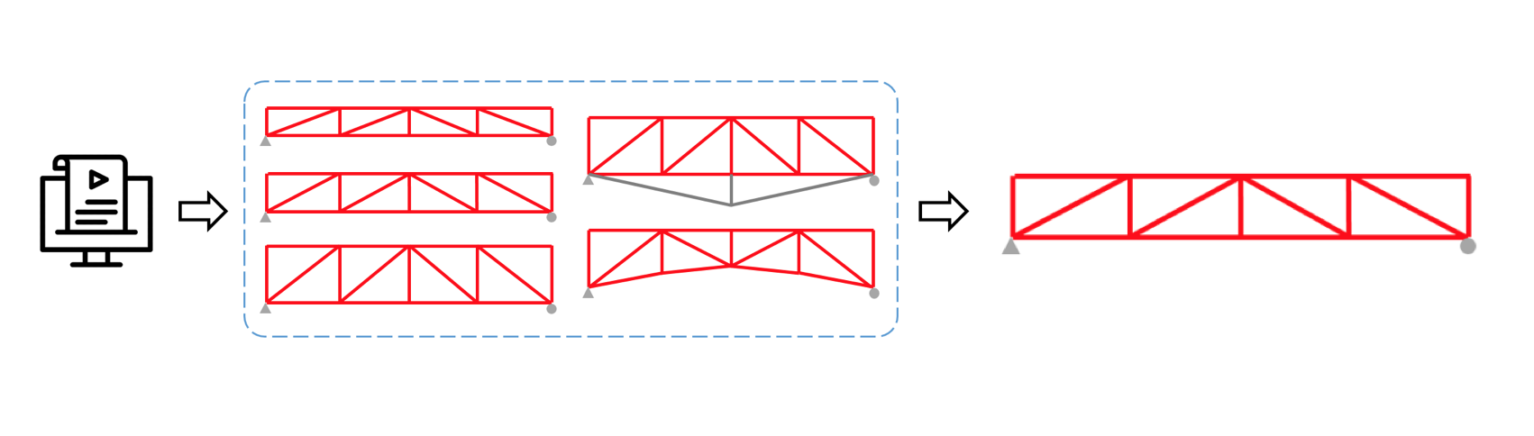
 2. At the member designing stage, an engineer can automatically select the constructive solution he needs through iterative calculation. For example, it is necessary to optimize the truss structure based on several criteria, such as optimal deflection, optimal weight, optimal truss height, the shape of the diagonals and cross-sections of the elements. Here, by preparing a script, through the API an engineer can automatically create and analyze all possible options iteratively, and stop at the most optimal one.
 3. Another important example of using the API is the transfer (conversion) of a ready-made FE model in SkyCiv from other software. For example, several companies are working on a common project and there is a need to carry out the structural analysis in different software. Such a need may arise for several reasons, either to compare the results for reliability, or in one of the software there are no analysis functions that are in the other software. It’s time-consuming the FE model creation from scratch in parallel. The most effective way is to have a ready-made FE model in one of the software and then transfer it to another via API.
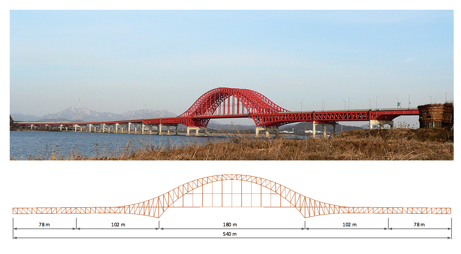
Example of an API FEM model for Verification: Banghwa Bridge, Korea.
In this article, as an example of the API application, an example of transferring the FE model from one software into SkyCiv is described below. Also an comparative analysis is performed. An example of the structure whose FE model is considered is a road bridge located in Seoul, Republic of Korea. The bridge and has the name Banghwa Bridge, crosses the Han River and it was built in 2000 year. The structure of the bridge is presented in the form of a continuous scheme with five spans. The central span is made in the form of an arch truss. Truss arches smoothly flow into the main trusses in adjacent spans. This gives a quite beautiful outline of the forms of the bridge from the front view. The length of the arch span is 180m. Adjacent spans have a length of 102m. The end spans have a length of 78m. The total length of the bridge section is 540m. Main structural members of the bridge are made of steel and include box and I-sections.
The FE model of the bridge will be transferred into the SkyCiv from the SIMULIA Abaqus software. Here, the FE model is completely composed of 3D Tymoshenko beam FE with 6th DOF. The material of all elements has an Elastic Modulus is 210000 MPa, density is 76.98 kN/m3. The stiffness of all elements is presented numerically. To describe the behavior of elements under compression-tension, bending, shear and torsion defined characteristics such as cross section area, effective areas, torsional resistance and moments of inertia.
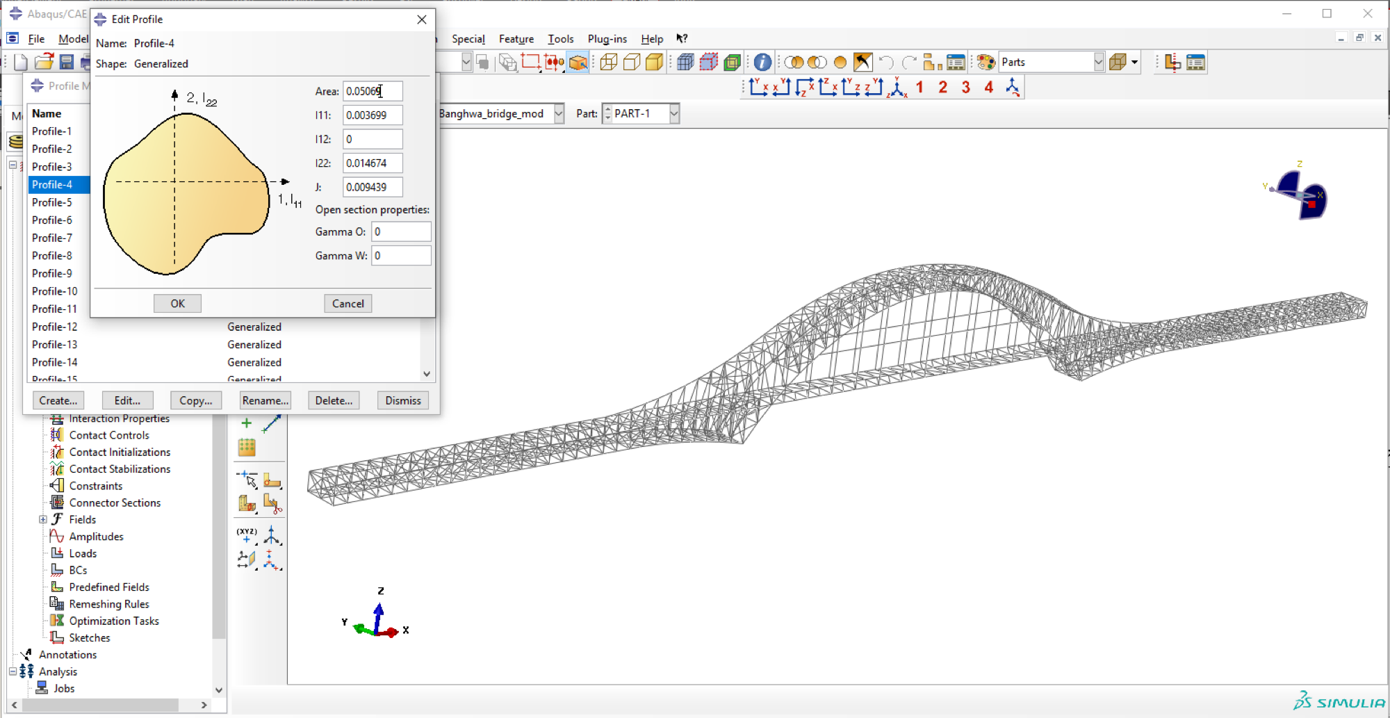
The SIMULIA Abaqus software allows to save all the FE model data as a text file. In which the data such as node coordinates, FE, material properties, boundary conditions, etc. are displayed as a set of script lines. Below is an example of such a representation.
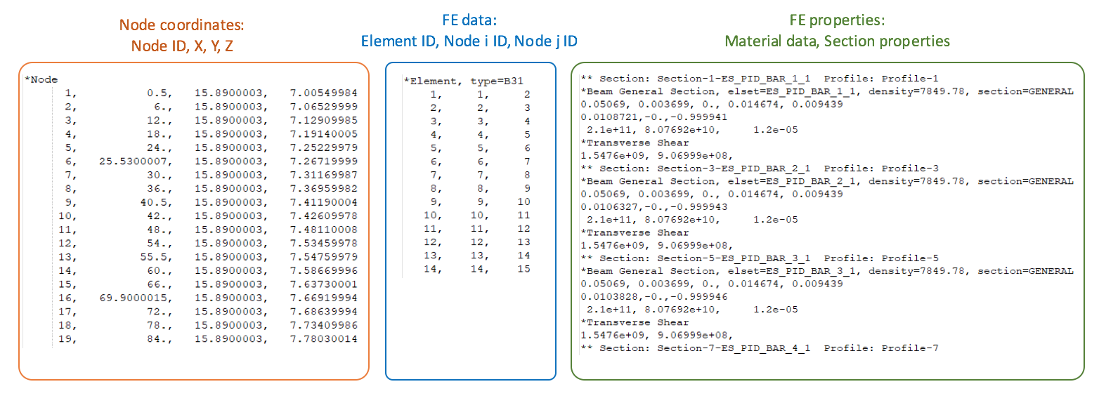
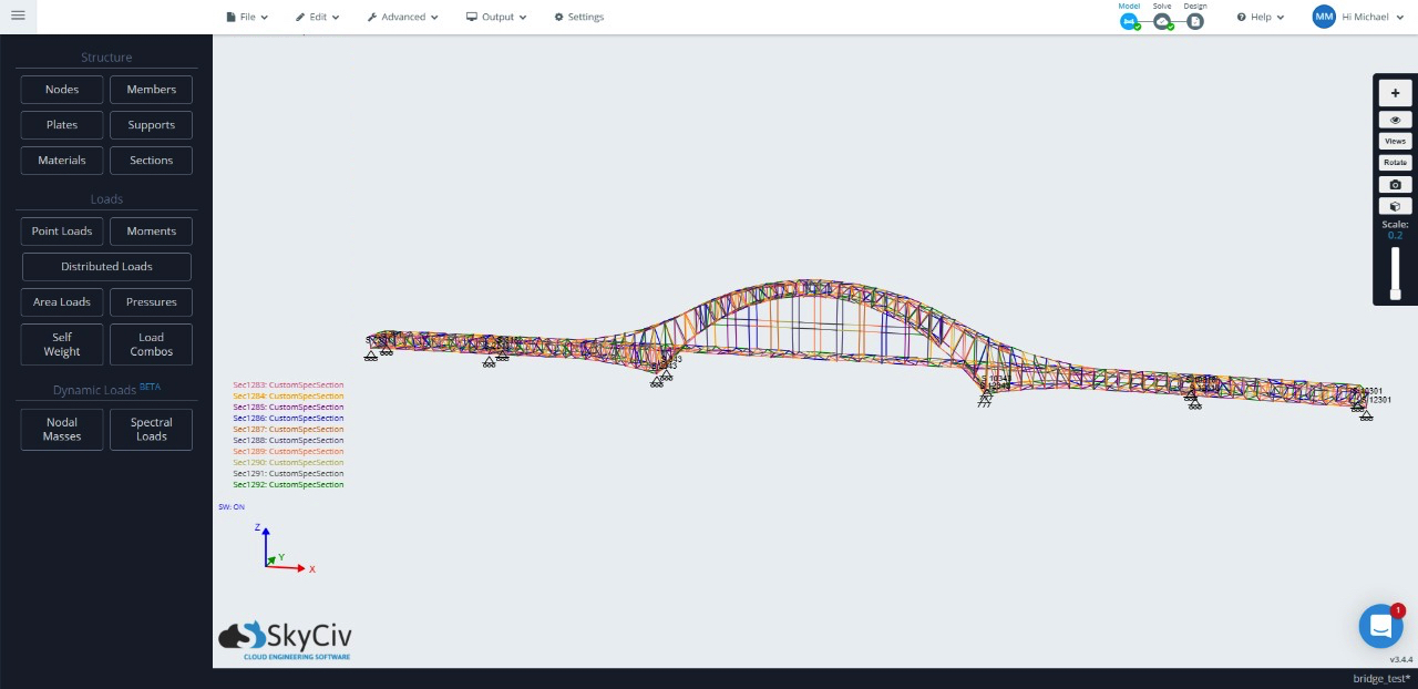
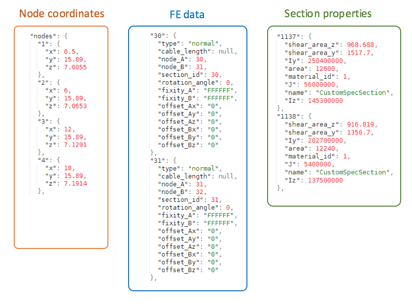
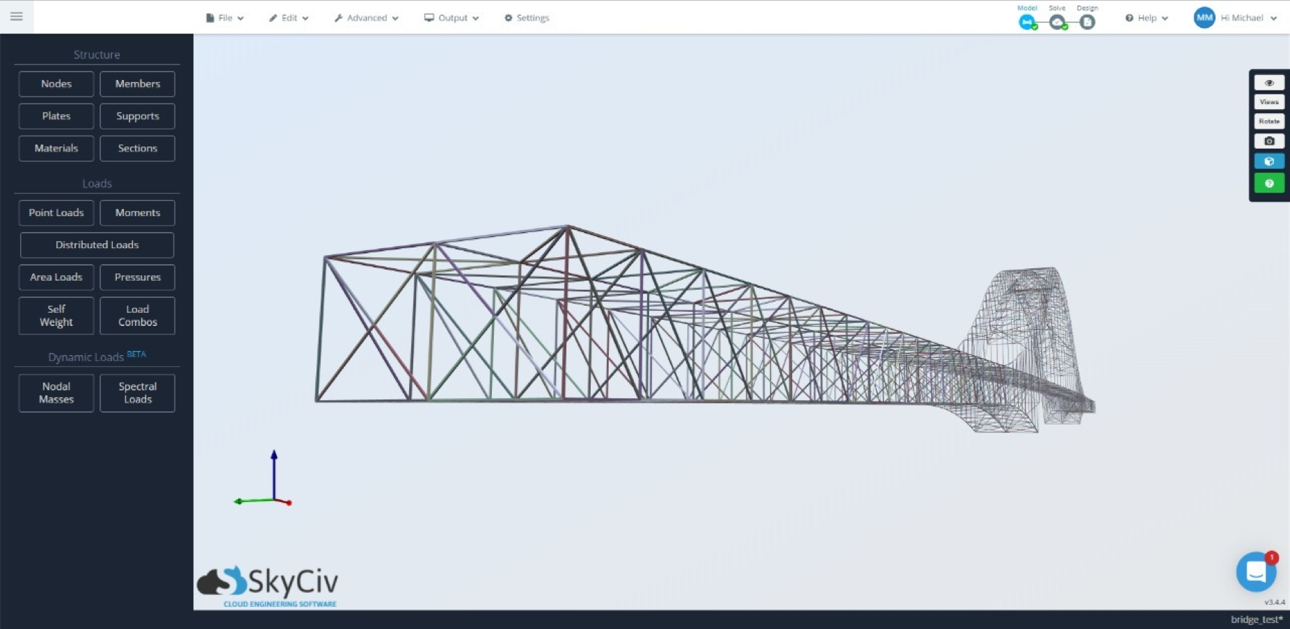
As a rule, a textual representation of the data by different software is compiled in such a way that it can be easily read and recognized using any programming language. From this, it is obvious that all the data of the FE model can be identified and transferred (converted) into a format that is recognized in SkyCiv. In this case, this is the JSON format. A detailed description of this format and the rules for its preparation can be studied here … (link). Below are the fragments of the converted JSON file and the view of the converted model in SkyCiv.
Verification of Results
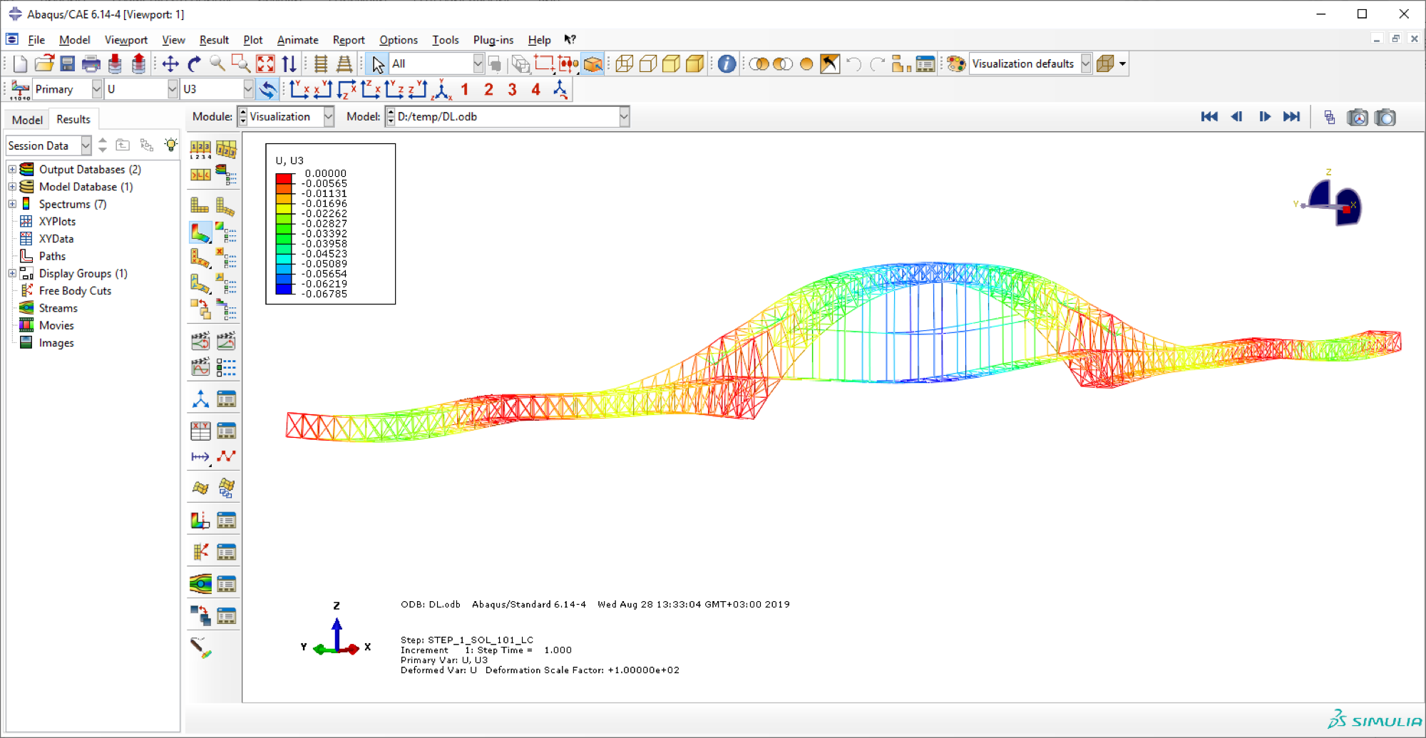
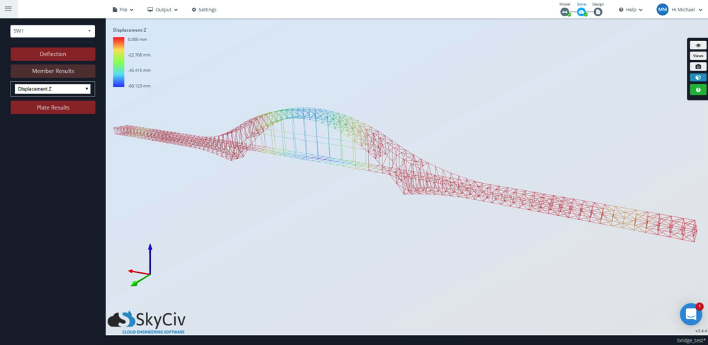
Now, a comparison of the analysis results in two software SIMULIA Abaqus and SkyCiv. Comparison is started from a static calculation with the action of the structure self-weight only. The self-weight is applied by the software automatically in the form of a distributed load, which is determined by multiplying the area of the element by the density of its material. Below is an example of the vertical deflection contour and the magnitude. The maximum displacement in SkyCiv is 68.12 mm. In SIMULIA Abaqus the maximum displacement is 67.85 mm. As can be seen the discrepancy is insignificant, less than 1%.
Deflection Results
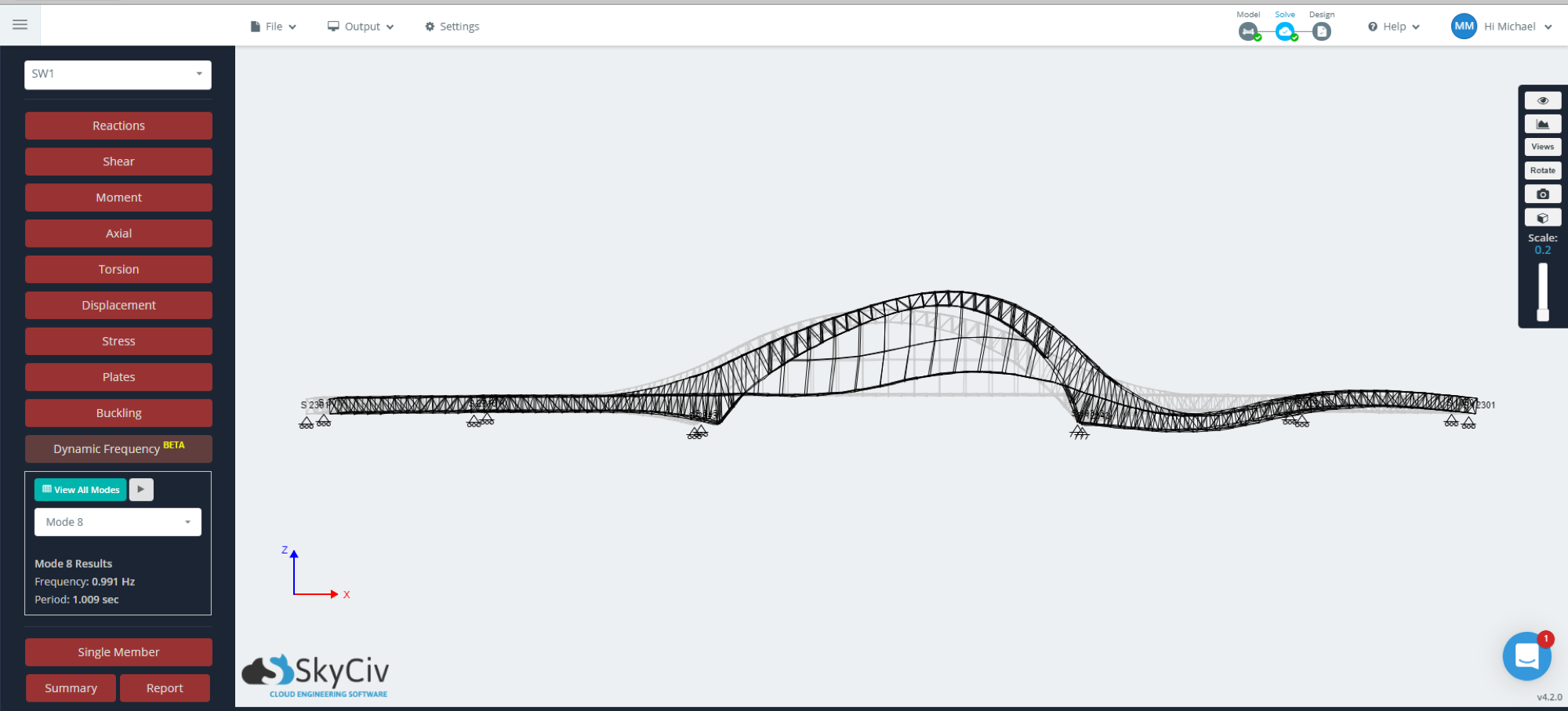
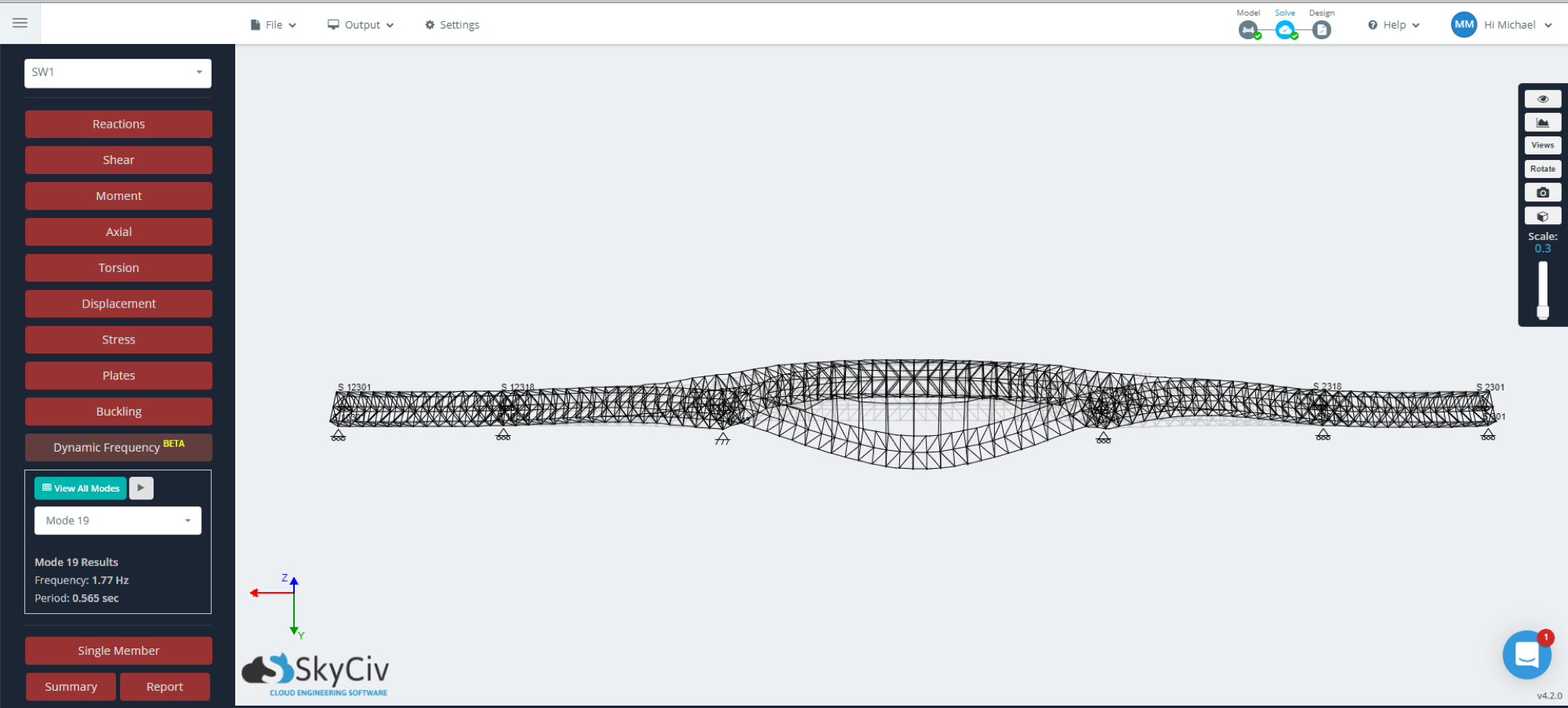
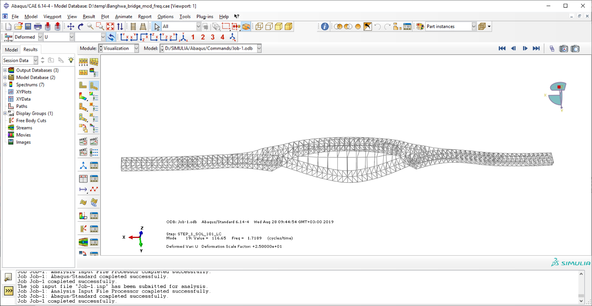
The following is a comparison of the eigenmodes and eigenvalues of structures based on the nodal masses of the elements converted from their own weight. The first eigenmode displays bending of members in the plane of the bridge. In SkyCiv the frequency is 0.991 Hz, at the same time in SIMULIA Abaqus the frequency is 0.981 Hz. The second eigenmode is characterized by the transverse bending of the bridge deck in the horizontal plane. In SkyCiv the frequency is 1.77 Hz and in SIMULIA Abaqus the frequency is 1.72 Hz. It can be seen the structure eigenmodes in both software are the same. The discrepancy between the eigenvalues between the software is within 3%.
Mode 8 Results
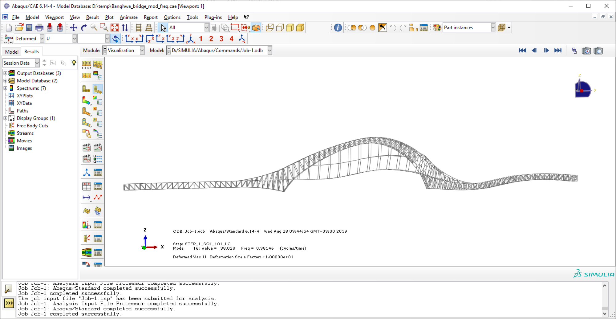
Mode 16 Results
The material presented above shows the process of effectively solving one of the tasks of applying the API in practice. Creating scripting APIs provides extensive opportunities for creating FE model if structure, including transferring existing models from other software for successful and accurate calculations in SkyCiv. The following materials will show other examples of using the API in SkyCiv.
Summary of Verification Results
| Result | SkyCiv | Third Party | Variance |
|---|---|---|---|
| Max. Deflection | 68.12 mm | 67.85 mm | 0.396% |
| Mode 8 Frequency | 0.991 Hz | 0.981 Hz | 1.009% |
| Mode 8 Shape | Visual Inspection Passed | ||
| Mode 19 Frequency | 1.77 Hz | 1.72 Hz | 2.825% |
| Mode 19 Shape | Visual Inspection Passed | ||

Structural Engineer, Product Development
MEng (Civil)
[email protected]