An Introduction and example use cases of Rigid Members
Rigid members are a powerful and effective member class, that can be used to simulate a fully rigid member. They are often used to transfer forces from one location to another, via some arbitrary, imaginary, infinitely rigid member. See the below video for more information on how they work, how to model them in software, and some use cases:
How to Use Rigid Members
To set a member as rigid, simply specify the member “Type” as “Rigid Link”. Note: you may have to toggle the advanced mode on to see the type attribute:
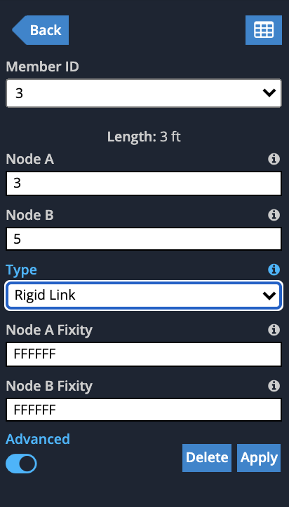
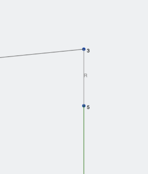
You will notice the options collapse (since they are not required for rigid links) but you can still control the end fixities, which essentially controls which loads are transferred. Once you click Apply, you will see that the rigid link is drawn in light grey color with a “R” symbol beside it:
Use Cases
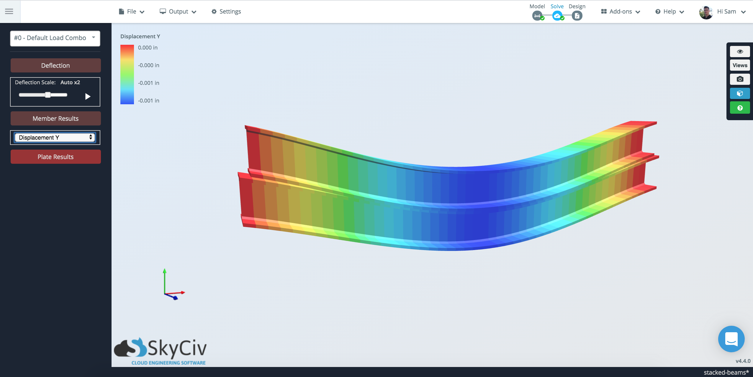
Stacked Beams

Line Hinges Between Plates
Rigid Links can be useful to define rigid connections between structures or elements. They are often thought of as imaginary stiff links that join members so they can translate and/or rotate together. A rigid link can also be used to manually control for member offsets or connections. Additionally you can change the fixity/releases in the rigid link to control what forces and effects it has on what it connects to. A good example of this is simulating Line Hinges to connect plates by hinges:
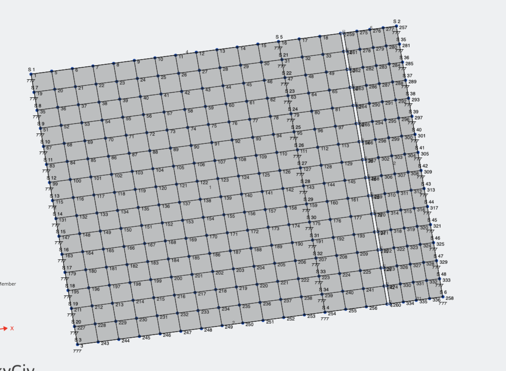
Start by adding two plates (that you wish to join by a hinge) and connect them with Rigid members with end fixities FFFFRR. These rigid links are connecting the gap in plates we see below:
Troubleshooting Common Issues
Master/Slave Connectivity
One of the most common errors from the solver when using rigid links is:
“Error Code 182: Node #5 is the master node (Node A) of Member #17 rigid link and cannot be used as the slave node (Node B) of another rigid link member. This might be due to an offset that is connected to a rigid link. Please remove the offset or rigid link to avoid this issue.”
If you’re receiving an error like this this guide will help you to fix these sorts of issues. The issue occurs because a Master node can have many slave nodes. However, a slave node can only have one master node. To put it simply, keep a single Master with many slaves coming from it. Consider the below example, which was causing the above error:
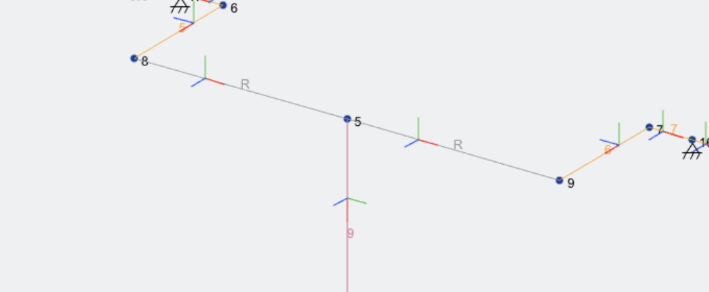
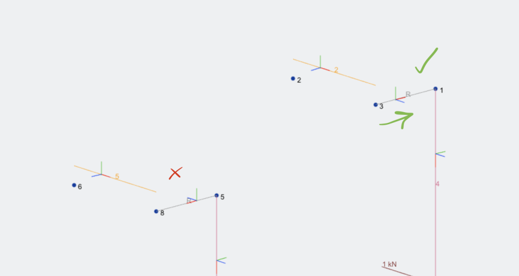
The best thing you can do is turn on the local axis and it will show the direction of master to slave by the red line (the member’s local x-axis). You can see that the red line is flowing left to right which would indicate that the Slave of one member is also a Master of another.
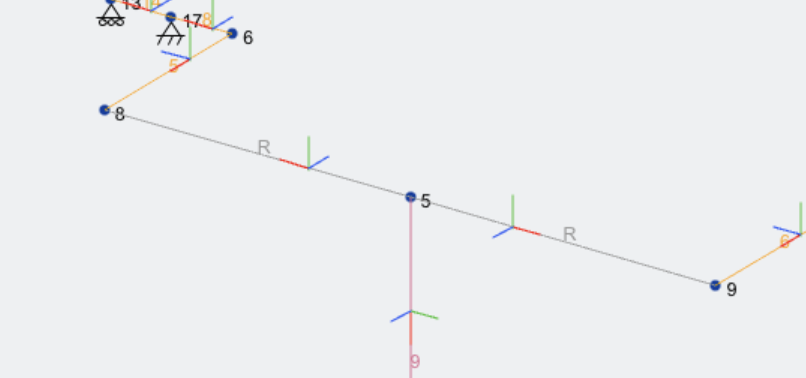
To fix this, flip the node IDs of the first member so you get this behaviour, with the rigid members sort of flowing out from a single node:
Using Rigid Links near Offsets
This is quite similar to the above issue, however they might occur automatically when using offsets. With offsets, the master node is always the node from which the member is offset from. The principal is the same as above, so to ensure this works, always have the rigid member starting from the offset node. Once again, the member local axis should flow out:
Adjacent Diaphragms
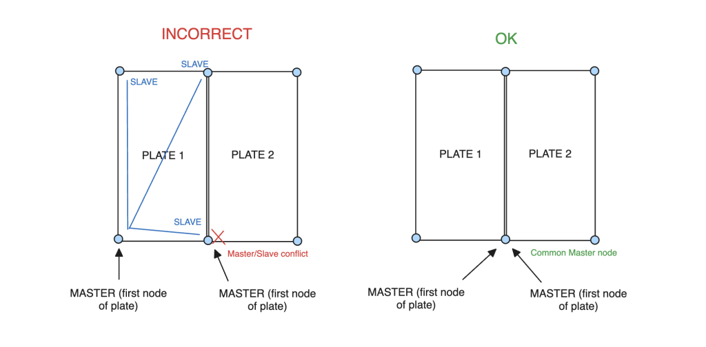
Having two connected diaphragms can also cause Master-Slave issues. It’s important to note that the Master node in a diaphragms is always the first node. This can create issues where two connected diaphragms have a common master/slave node. So if you want two adjacent rigid diaphragms, you would need to set it up like so:
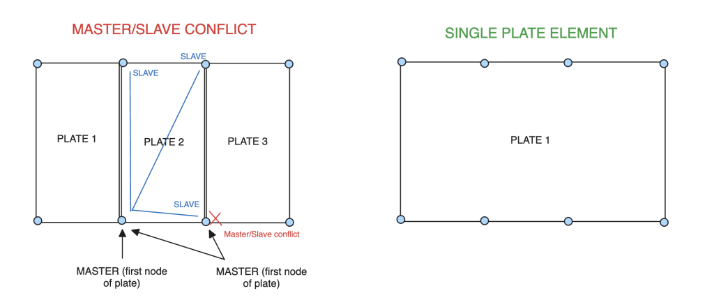
The problem can be worsened if there are more than two diaphragms, since there is no way to share a common master node. In this case, it is better to replace the whole plate with a single rigid diaphragm, remember you can have more than 4 nodes for a plate, so this should be a pretty acceptable workaround in most cases:
Slaves Cannot be Supports
This is a general structural analysis limitation.