To calculate the wind load pressures for a structure using SkyCiv Load Generator, the process is to define first the code reference. From there, the workflow is to define the parameters in Project Tab, Site Tab, and Building Tab, respectively. However, only paid users can use this wind load calculation for this structure type. With a Professional Account or by purchasing the standalone Load Generator module, you can use all the features of this calculation as long as you want. You can purchase the standalone module thru this link.
Calculating the wind speeds can be a complex process in AS/NZS 1170.2 (2021) for site locations in Australia and New Zealand. That’s why SkyCiv has developed an online wind load tool to help calculate the design wind speed and pressures via our interactive Google Map. Users can also click and drag the marker to move the site location:
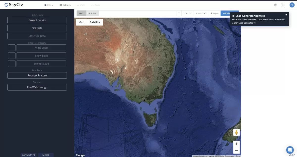
Figure 1. SkyCiv Load Generator UI
Site Data
Basic Wind Speed
The software will calculate the basic wind speed, VR, based on AS/NZS 1170.0 and AS/NZS 1170.2.
Serviceability and Ultimate Limit State Wind Speeds
Users can also pull the Serviceability Limit State (SLS) and Ultimate Limit State (ULS) wind speeds for both Australia and New Zealand. It uses the Annual Probability of Exceedance for based AS/NZS 1170.0 and calculated via the following input. Simply define in the following input:
- Country – Australia or New Zealand
- Design Working Life – how long the structure is intended to be used. For instance, is the structure used for construction purposes (e.g. scaffolding) or is the design working life longer term, for say buildings and bridges. The longer the design working life, the higher the basic wind speed (to account for significance). Here, the SLS only increases up to DWL of less than 25 years.
- Importance Level – The importance level is governed the type of structure and it’s potential impact. Click the (i) for more information about which importance level is correct for your structure.
- Project Address – the address where the site is located
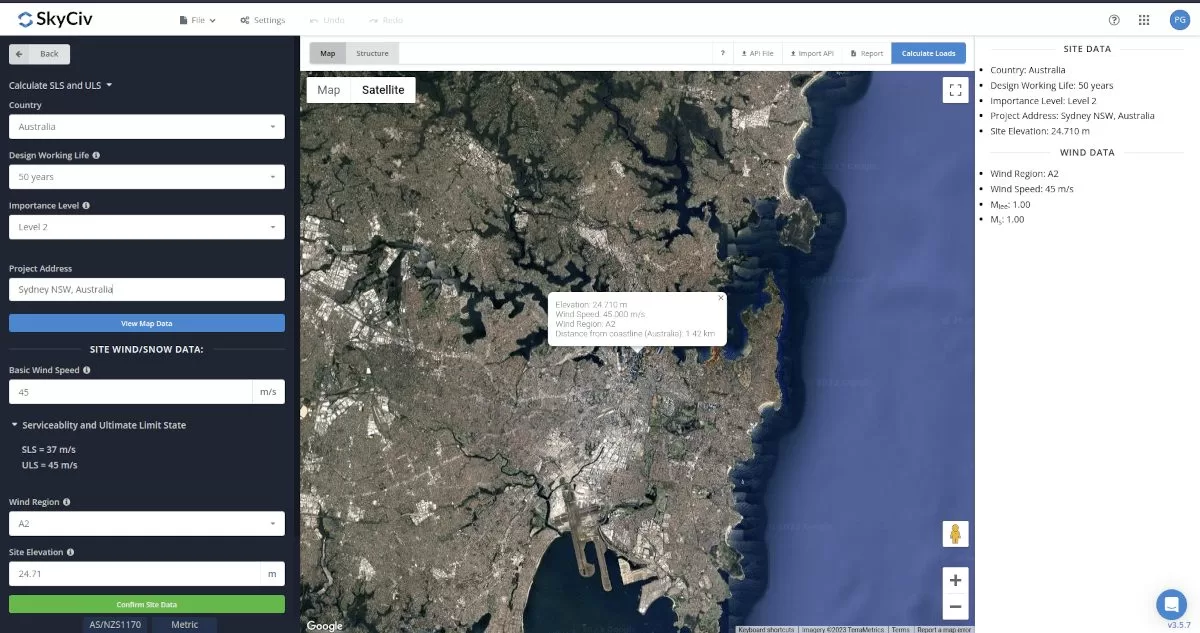
Here is an example of the SkyCiv Load Generator getting the basic wind speed for Queenstown, New Zealand (by default the basic wind speed will be the largest of SLS and ULS values):
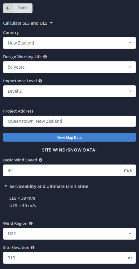
Note that the user should double check if the wind region detected for the location is accurate based on Figures 3.1(A) and 3.1(B) of AS/NZS 1170.2 in order to obtain the appropriate wind speed for the structure. The Site Data should look like this:
Site Input Parameters for Wind Load Calculation
Basic Wind Speed- the basic wind speed to be used in calculating the design wind pressure. This is automatically determined based on Annual Probability of Exceedance and Project Address and can be modified by the user
Wind Region – Used in determining the basic wind speed V value
Site Elevation – determined from Google Maps API
Once the parameters above are completed, we can now proceed to the Structure Data section.
Structure Data
The structure data and the wind and snow parameters are separated into different accordions. In order to calculate design wind pressures, the wind load checkbox should be checked. You need to define first the Structure you are analyzing. Right now, the available structures for AS/NZS 1170.2 are as follows:
- Building – supports the following roof profile:
- Gable, Hip, Monoslope (enclosed, partially enclosed, or partially open)
- Troughed, Pitched, Open Monoslope (open)
- Solar Panels
- Ground-mounted (array)
- Rooftop
- Pole
In this documentation, we will focus on Solar Panels structure.
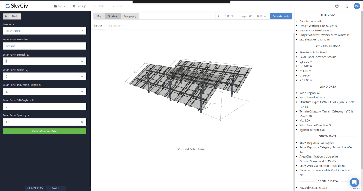
Structure Input Parameters for Ground-mounted Solar Panel (array)
Solar Panel Location – Set to Ground
Solar Panel Length – the dimension of the solar panel as shown in the figure
Solar Panel Width – the dimension of the solar panel as shown in the figure
Solar Panel Mounting Height – the dimension of the solar panel as shown in the figure. Used in calculation of velocity pressure
Solar Panel Tilt Angle – the angle of tilt the solar panel makes with the level ground
Solar Panel Spacing – spacing of the solar panel arrays
Structure Input Parameters for Rooftop Solar Panel
Solar Panel Location – Set to Rooftop
Solar Panel Length- the dimension of the solar panel as shown in the figure
Solar Panel Width – the dimension of the solar panel as shown in the figure
Roof Profile – Used in pressure coefficient values based on the selected roof profile and roof pitch angle
Building Length – the dimension of the solar panel as shown in the figure
Building Width – the dimension of the solar panel as shown in the figure
Mean Roof Height – the dimension of the structure from ground to the middle height of the sloping roof. Used in calculation of velocity pressure
Roof Pitch Angle – the roof slope in degree. Used in calculation of pressure coefficients
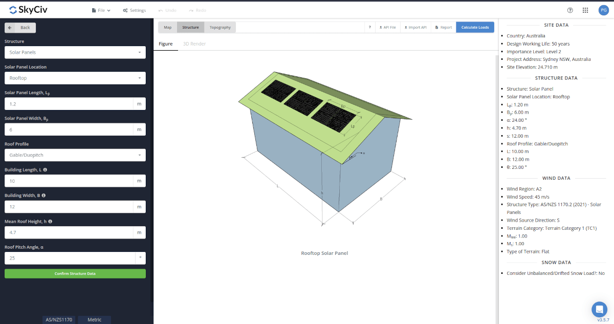
Figure 5. Structure data input for rooftop solar panel.
Once the parameters above are completed, we can now proceed to the Wind Load Parameters section.
Wind Data
To proceed with our wind load calculation, we need to check the checkbox first beside the Wind Load button. By default, this is checked when the site wind data has been defined.
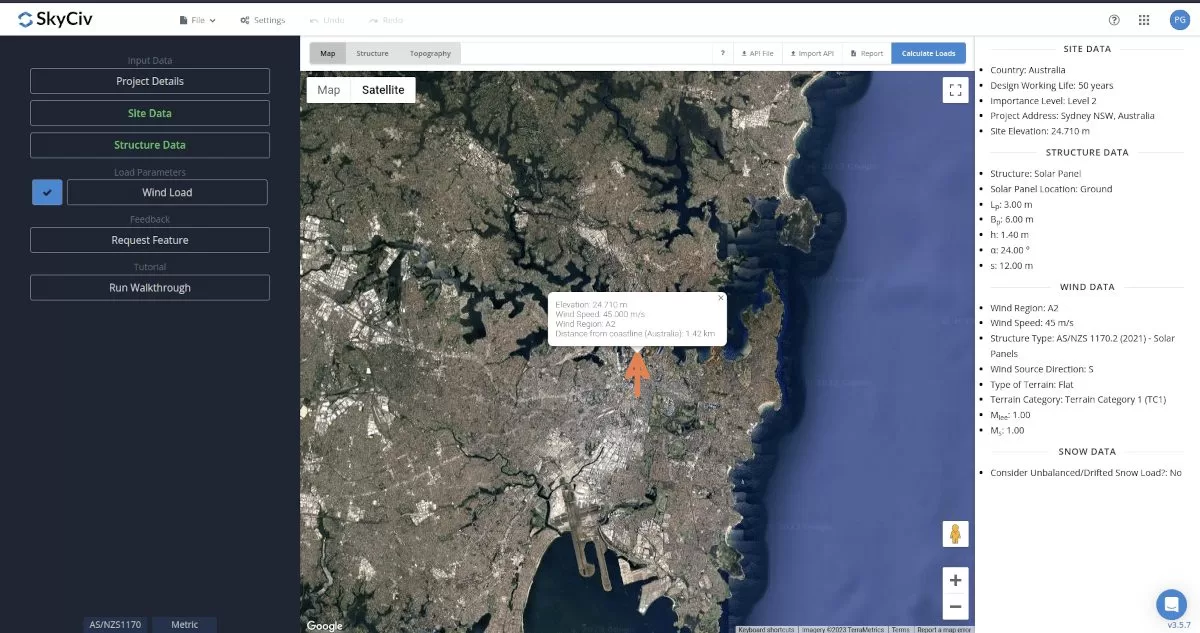
Figure 6. Checkbox for Wind Load Data.
The next step, is to define the Wind Source Direction the corresponding Terrain Category of the upwind area. The Wind Direction parameter is used in obtaining the upwind (left side) and downwind (right side) ground elevations to calculate for Hill-shape Multiplier, Mh. In addition, the Terrain Category is used in determining the Terrain/Height Multiplier Mz,cat. For standalone users or Professional account, you determine the select the worst wind source direction by clicking the View Design Wind Inputs for All Directions button so you can set the Terrain Category per upwind Wind Source Direction as represented by a 45-degree sector.
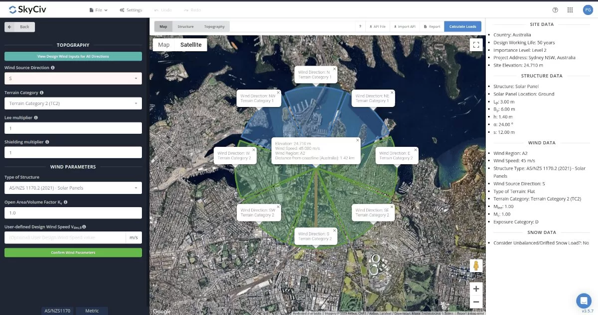
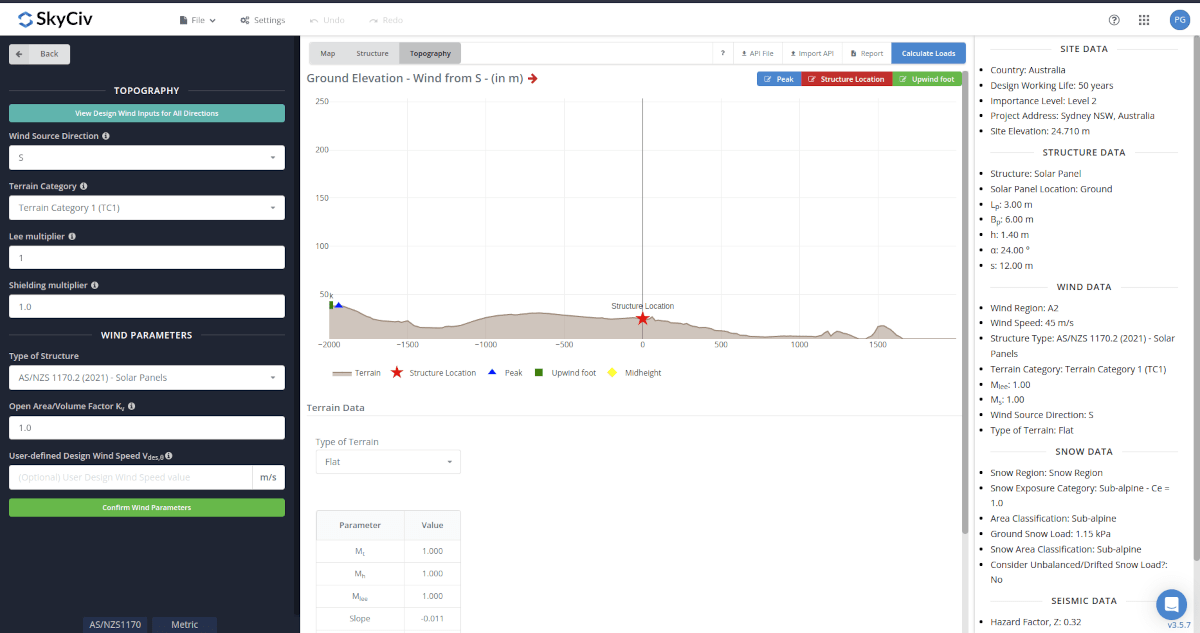
Figure 8. Elevation Data from Google Maps for upwind (left) and downwind side (right).
Topography Input Parameters
Wind Source Direction – used to obtain the elevation data on a specific direction section of the area. These elevation ata are used in determining the Hill-shape Multiplier, Mh
Lee Multiplier – (for New Zealand) used as value for Mlee and used in determining the Topographic Multiplier, Mt. Default value is equal to 1.0
Shielding Multiplier – used as value for Ms and used in determining the design wind speed. Default value is equal to 1.0
Type of Terrain – Options to select Flat, Escarpment, Hills and Ridges
H – Height of obstruction/terrain. For type of terrain is set to option other than Flat terrain, this is used in calculating the Hill-shape Multiplier, Mh
Lu – Horizontal distance from peak to the middle height of the obstruction. For type of terrain is set to option other than Flat terrain, this is used in calculating the Hill-shape Multiplier, Mh
x – Horizontal distance of structure to the peak of the obstruction with the peak as the point of reference. For type of terrain is set to option other than Flat terrain, this is used in calculating the Hill-shape Multiplier, Mh
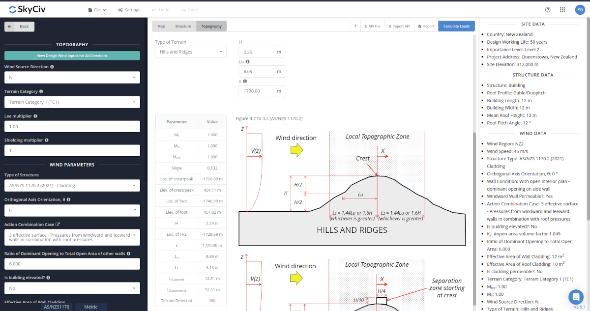
Figure 9. Topography Parameters for AS/NZS 1170.2.
Wind Input Parameters for Solar Panels (Ground and Rooftop)
Type of Structure – Required to be set to AS/NZS 1170 Solar Panels
User-defined Design Wind Speed Vdes,θ – For user-defined override on the Design Wind Speed used in the wind pressure calculation
Figure 10. Wind Parameters for Ground and Rooftop Solar Panels.
After all these parameters are defined, the next step is to click the Calculate Loads on the upper right side of the UI.
Results
The results of the calculation are shown as follows:
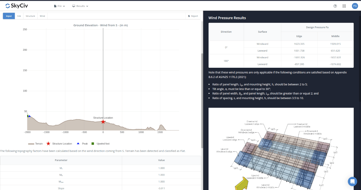
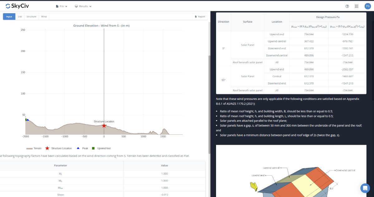
Figure 12. Wind results for Rooftop Solar Panels.
The summarized results are shown on the right side of the screen. Other results are shown on the detailed report.
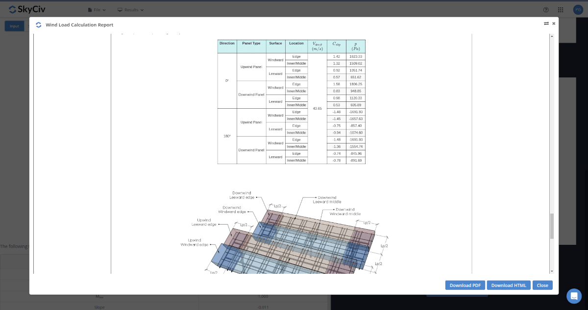
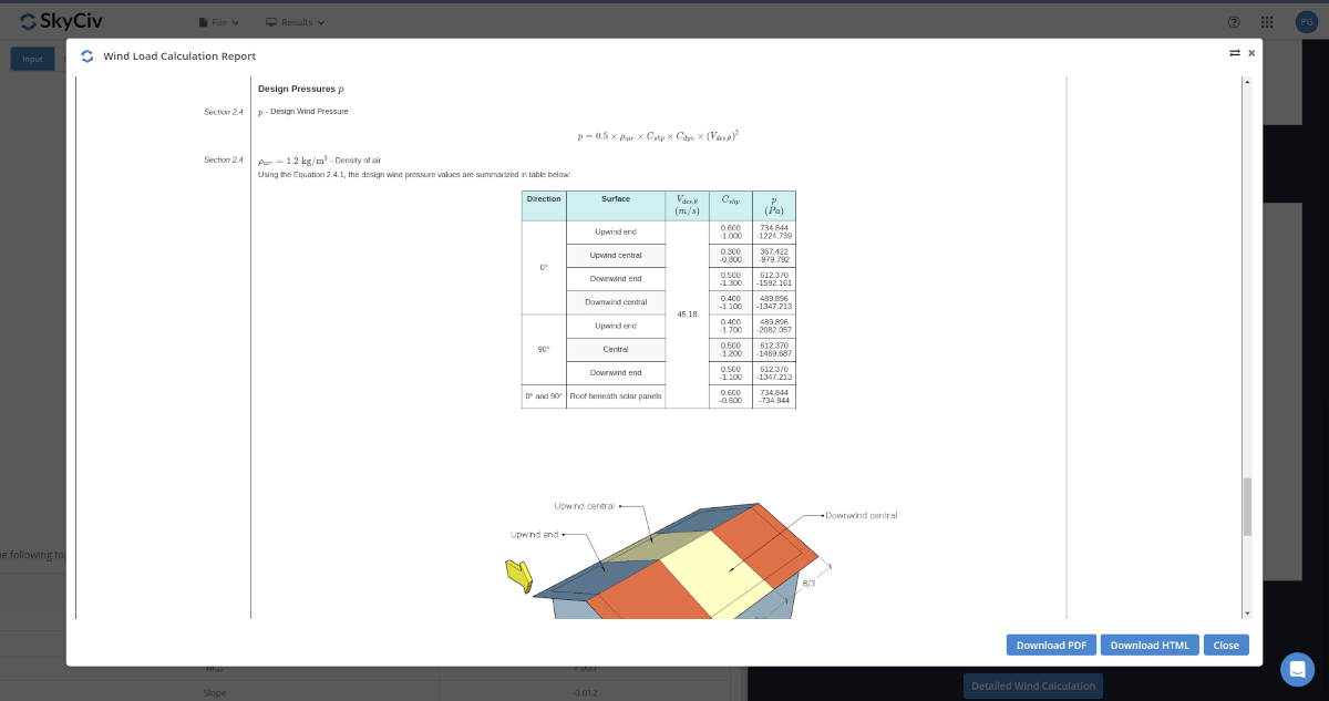
Detailed Calculation
The detailed wind load calculations can be accessed only by Professional account users and those who purchased the standalone load generator module. All the parameters and assumptions used in the calculation are displayed on the report to make it transparent to the user. You can download a sample detailed calculation thru the following links:
AS/NZS 1170.2 Detailed Report for Ground-mounted Solar Panels
AS/NZS 1170.2 Detailed Report for Rooftop Solar Panels
Ground Solar Panel
For additional resources, you can use these links for reference: