A walk-through and example of calculating snow drift loads and how to apply them
Roof designs usually present multitudes of roof elevations and rarely offer one single roof height. Because of this, there are roof areas higher and lower than each other and are subject to snow drifts. The amount of additional snow load, or surcharge, can and will make a large impact of the design of the members in these areas.
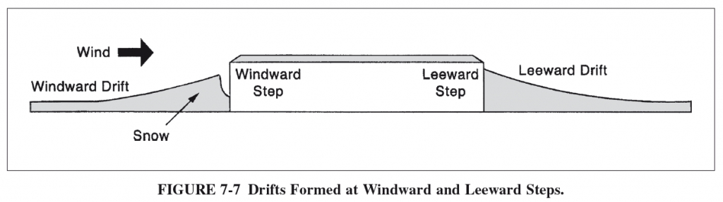
Geometry of the roof and the direction of the wind are the two drivers that lead to snow drifts. The two directions of wind that cause snow drifts are “windward” and “leeward”. Windward snow drifts occur when wind blows snow from a lower elevation roof towards the wall of an adjacent, higher roof. Leeward snow drifts occur when wind blows snow off of a higher elevation roof down onto an adjacent lower roof. See Figure 7-7 from ASCE 7-10 below for a succinct depiction:
Lets assume our project is in Madison, Wisconsin and we have already calculated our balanced, roof snow load here. From our example, our ground load and flat roof snow load were found to be 30 psf and 21 psf, respectively. Provisions on how to calculate the snow drift surcharge for structures can be found in Section 7.8 of ASCE 7-10.
Our example structure’s roof has two varying roof heights and therefore we need to calculate the snow drift surcharge and apply it to our members. In our case, our beams are spaced at 10 feet.
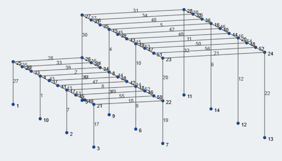
Figure 1: Isometric view of our example structure
Lets first gather the relevant geometric information about our structure. The lower bay and upper bay size is 25 feet and 37 feet, respectively. The lower and higher roof elevations are 15 feet and 30 feet from grade, respectively. Most of the geometric values can be associated with variables. Lets take a look at all the pertinent variables for this calculation.
\({p}_{g}\) = ground snow load
\({l}_{u}\) = length of upper roof
\({l}_{l}\) = length of lower roof
\({h}_{d}\) = height of snow drift
\({w}\) = width of snow drift
\({h}_{b}\) = height of balanced snow load
\({h}_{c}\) = clear height from top of balanced snow load to closest point of adjacent roof
\({h}_{r}\) = height difference between roofs
\({p}_{s}\) = design snow load from Chapter 7
\({γ}\) = snow density
\({p}_{d}\) = snow drift load
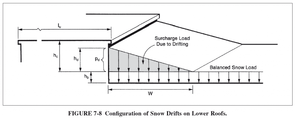
Take a look at Figure 7-8 from ASCE 7-10 for a depiction of many of these terms and what they visually represent:
Finding the Snow Drift Surcharge Load
Now that we have identified what the variables are, the snow loading configurations, and the geometric constraints of our structure, lets calculate the snow drift.
First, find if snow drift loading is necessary, per ASCE 7.7-1:
If \({h}_{c}/{h}_{b} < 0.2\), then snow drift application is not necessary.
\({h}_{b} = {p}_{s}/{γ}\), where:
\({γ} = 0.13{p}_{g} + 14 ≤ 30 pcf\)
\({γ} = 0.13*(30) + 14 = 17.9 pcf ≤ 30 pcf \)
\({h}_{b} = {21 psf}/{17.9 pcf} = 1.17 ft\)
\({h}_{c} = {h}_{r}-{h}_{b}\)
\({h}_{c} = 15 ft – 1.17 ft = 13.8 ft\)
\({h}_{c}/{h}_{b} = 13.8 ft/1.17ft = 11.8 > 0.2\) and therefore, snow drift loading is necessary.
Second, find maximum drift height between both windward and leeward directions:
The height of the drift for both wind directions can be found using the equation found in Figure 7-9 of ASCE 7-10, shown below:
\({h}_{d} = 3/4*(0.43({l}_{l})^{1/3}({p_g}+10)^{1/4}-1.5)\) for windward drift
\({h}_{d} = 0.43({l}_{u})^{1/3}({p_g}+10)^{1/4}-1.5\) for leeward drift
Windward drift height:
\({h}_{d} =3/4*(0.43(25 ft)^{1/3}(30 psf+10)^{1/4}-1.5)\)
\({h}_{d} = 1.25 ft\)
Leeward drift height:
\({h}_{d} = 0.43(37 ft)^{1/3}(30 psf+10)^{1/4}-1.5\)
\({h}_{d} = 2.1 ft\)
The maximum drift height between the windward and leeward drift height will be used for design, therefore:
\({h}_{d} = 2.1 ft\)
Next, find the width of the snow drift surcharge:
The width of the snow drift load, \({w}\), depends on \({h}_{c}\) and \({h}_{d}\)
Per Section 7.7.1,
If \({h}_{d} ≤ {h}_{c}\), then \({w} = 4{h}_{d}\)
If \({h}_{d} > {h}_{c}\), then \({w} = 4{h}_{d}^2/{h}_{c}) and subsequently \({h}_{d} = {h}_{c}\)
In our case, \({h}_{c} = 13.8 ft\) and \({h}_{d} = 2.1 ft\), and therefore:
\({h}_{d} ≤ {h}_{c}\), and
\({w} = 4*(2.1 ft)\)
\({w} = 8.4 ft\)
Note, per ASCE 7-10 the snow drift width shall never exceed \(8{h}_{c}\)
Last, calculate the snow drift surcharge load:
To find the maximum surcharge load, multiply the drift height by the snow density:
\({p}_{d} = {h}_{d}{γ}\)
In our case,
\({p}_{d} = (2.1 ft)*(17.9 pcf)\)
\({p}_{d} = 37.6 psf\)
The maximum snow drift surcharge load is then superimposed on the balanced snow load:
\({p}_{max} = {p}_{d}+{p}_{s}\)
\({p}_{max} = 58.6 psf\)
Applying the Snow Drift Surcharge Loads
Lets look at the middle frame of our structure. The distributed area for the beams in this plane is 10 ft because of the constant 10 ft beam spacing. Figure 2 shown below depicts the balanced snow load of 21 psf applied to the roof of our structure. Note, all values are unfactored, service loads.
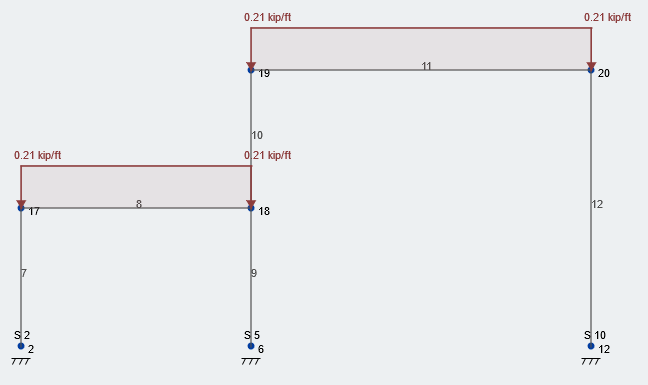
Figure 2: Typical loading condition of balanced snow load
Now, lets take the snow drift surcharge load and superimpose it on our structure. Figure 3 depicts the additional drift load at the correct location. As you can see, our total snow load is 58.6 psf – rounded up to 59 psf – located at the face of the wall and then decreases linearly over the 8.4 ft drift width back to the constant balanced snow load. This loading condition follows the entire length of the wall, in our course, the length of the structure.
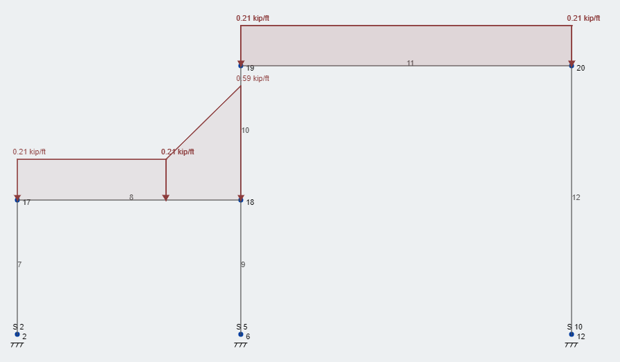
Figure 3: Typical loading condition service level snow design loads
At this point the snow loads are ready for analysis in conjuncture with other load cases and load combinations based on ASCE 7-10 and other pertinent building codes. Make sure to read through Chapter 7 of ASCE 7-10 for more information about successive provisions for partial snow loading and unbalanced snow loading, as those conditions were not evaluated here.
References:
- Minimum Design Loads for Buildings and Other Structures. (2013). ASCE/SEI 7-10. American Society of Civil Engineers.