Pressures in SkyCiv Structural 3D are a force applied to a surface per unit area over which the force is distributed. Pressures are ONLY applied to plates. Users can apply Area Loads to other model elements.
Pressures that are applied at an angle to the plate can be specified by providing the X, Y, and Z components.
To apply pressure on a plate, simply specify values for:
- Pressure ID – The numerical ID used to identify each pressure.
- Plate ID – The plate number where the pressure is applied.
- X Magnitude – Magnitude of pressure in the X-direction.
- Y Magnitude – Magnitude of pressure in the Y-direction.
- Z Magnitude – Magnitude of pressure in the Z-direction.
- Load Group – Loads can be grouped with Load Group numbers. The Load Groups can then be multiplied by a factor in the ‘Load Combos’ menu. Optional.
- Advanced Input
- Load Distribution – Uniform or Linear
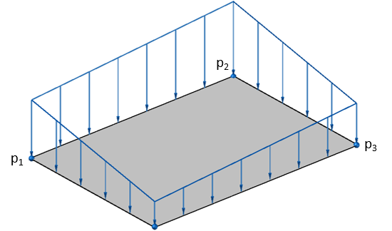
If the Linear Load Distribution is selected from the advanced input, new values are required:
- Pressure ID – The numerical ID used to identify each pressure.
- Plate ID – The plate number where the pressure is applied.
- Load Direction – Direction of the linear pressure.
- P1 Node ID – See the picture below for reference
- P1 Magnitude – See the picture below for reference
- P2 Node ID – See the picture below for reference
- P2 Magnitude – See the picture below for reference
- P3 Node ID – See the picture below for reference
- P3 Magnitude – See the picture below for reference
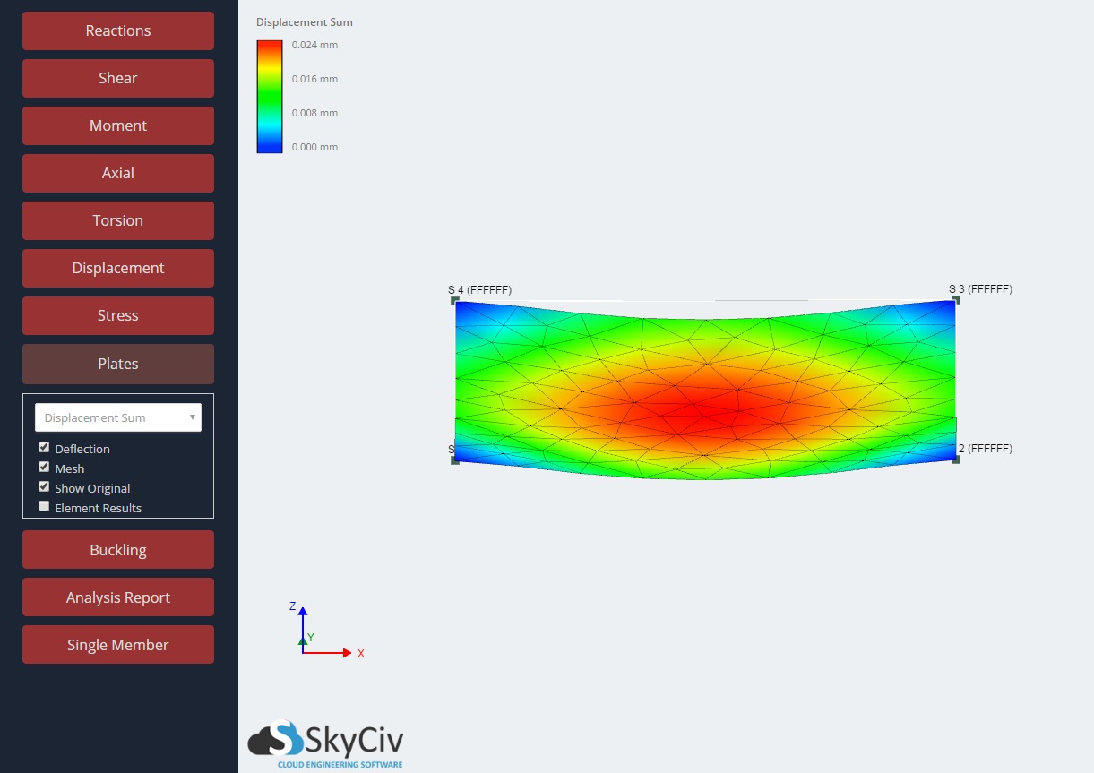
Example 1 – Applying a uniform pressure to a plate
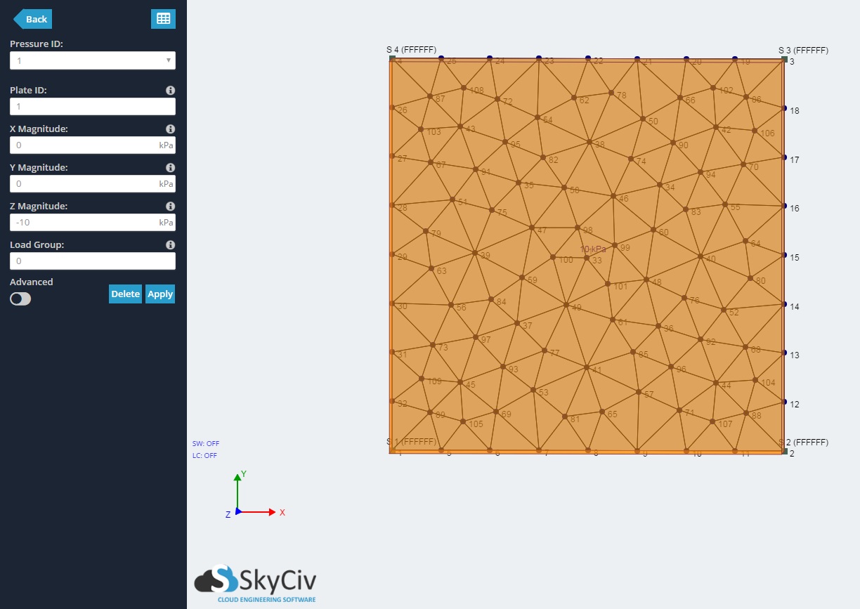
In this example, we will apply pressure to a plate that has already been created, had supports applied to its nodes, and has been meshed. Check out the Software Documentation about Modelling Plates and Meshing Plates if you haven’t.
1) Click into the ‘Pressures’ menu from the left navigation bar. Enter 1 for the ‘Plate ID’ and -10 for the ‘Z Magnitude’. Click Apply.
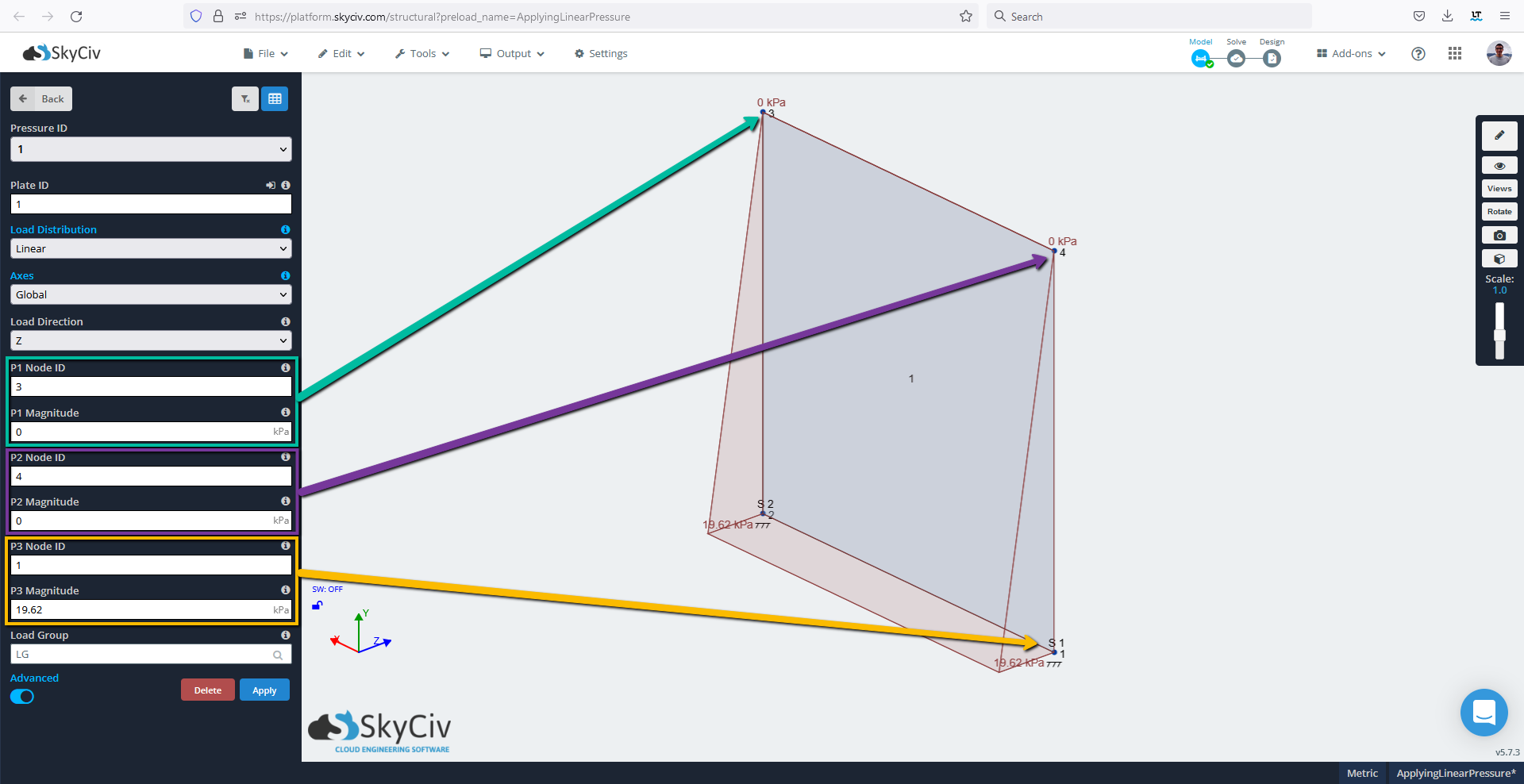
Example 2 – Applying a linear pressure to a plate
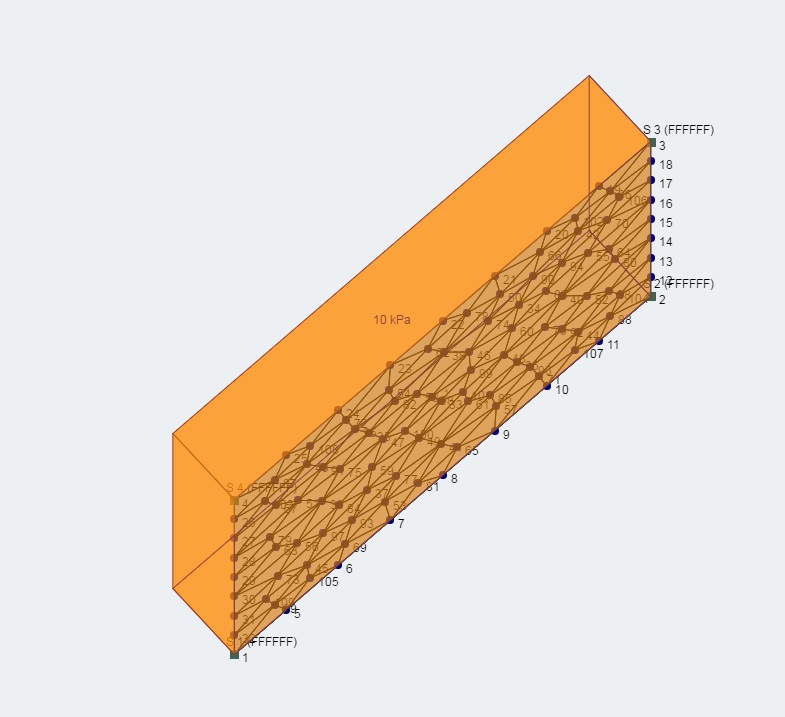
In this example, we will apply variable linear pressure, following the distribution of hydrostatic pressure, to a plate that has already been created, had supports applied to its nodes, and has been meshed. Check out the Software Documentation about Modelling Plates and Meshing Plates if you haven’t.
1) Click into the ‘Pressures’ menu from the left navigation bar. Toggle the Advanced input and enter:
- Plate ID: 1
- Load Distribution: Linear
- Axes: Global
- Load Direction: Z
- P1 Node ID: 4
- P1 Magnitude: 0
- P2 Node ID: 3
- P2 Magnitude: 0
- P3 Node ID: 2
- P3 Magnitude: 19.62
2) Click Apply.
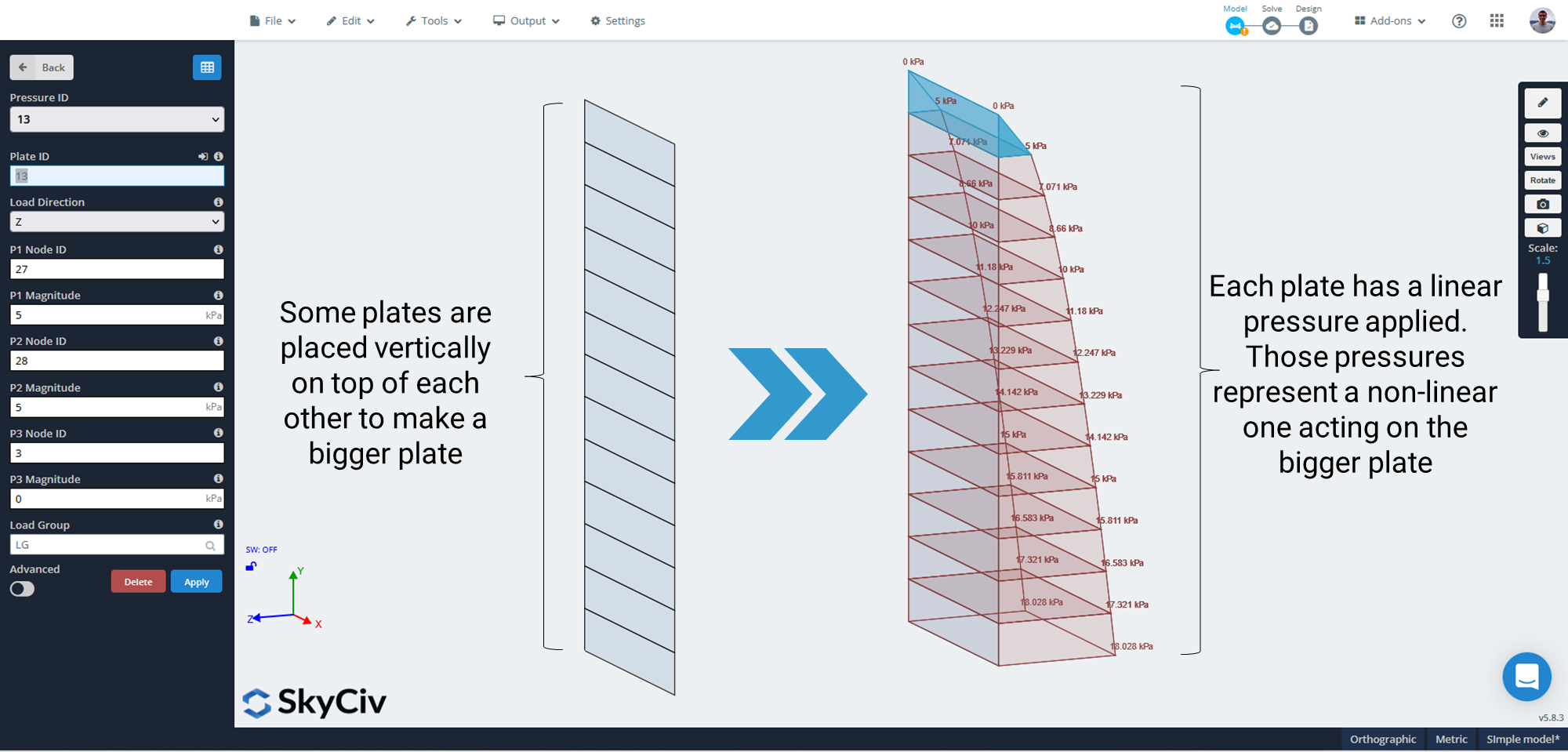
Example 3 – Applying a non-linear pressure to a plate
In some cases, a linearly variating pressure is not accurate enough for representing the actual distribution of the pressure acting on a plate. For example, the pressure exerted by the grains or powder stored in a silo might follow a highly non-linear distribution. Using SkyCiv S3D, it is possible to model non-linearly distributed pressures on plates, by discretizing the pressure distribution using some linearly varying pressures.
It is always possible to manually do it, creating each plate and then applying a linear pressure on each plate. However, taking advantage of the datasheet functionality offered by SkyCiv and an external spreadsheet, this modeling process becomes much easier. If not sure about how to use SkyCiv’s datasheets, please check our documentation on datasheets. At SkyCiv, we prepared a template spreadsheet to aid the process:
Step 1 – Define four nodes as the plate boundary
Manually create the nodes that define the global plate’s boundary. If using the template spreadsheet, make sure the coordinates are pasted in clockwise order, starting from the bottom-left corner.
Step 2 – Create the rest of the nodes
Add all the intermediate nodes required for creating the small plates. If using the template spreadsheet, simply paste the new nodes generated into S3D.
Step 3 – Create the plates
Using the previously created nodes, add all the plates to the model. If using the template spreadsheet, simply paste the plates table into the plates’ datasheet in S3D.
Step 4 – Assign a linear pressure to each plate
Create the linearly variating pressure for each plate, according to the distribution followed by the stored/retained material.
Note: The template spreadsheet assumes that “Y” is the vertical axis, and the global plate is parallel to this axis.