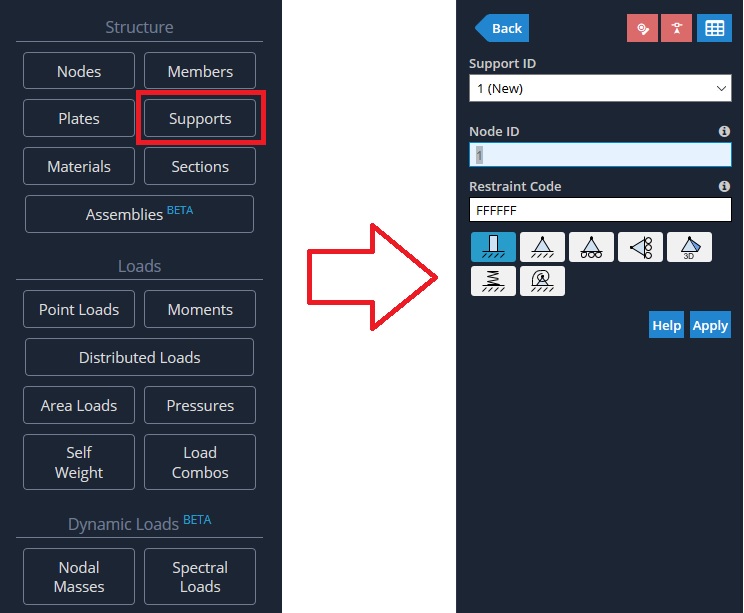
Supports need to be added in order to restrain the structure. If no supports were present then the structure would not be static and be unsolvable. It is important to remember that a structure must be restrained in every direction at some point by any of the supports. i.e. every degree of freedom must be accounted for by at least one ‘F’ in the structure.
Similar to the connections between members, the supports are given a 6-digit code to specify which of the node’s degrees of freedom are restrained. Each of the degree of freedom’s must be defined as either Fixed (‘F’), Released (‘R’) or Spring(‘S’). The degrees of freedom are in the following order:
- X Translation
- Y Translation
- Z Translation
- X Rotation
- Y Rotation
- Z Rotation
There are 3 types of letters (or of releases) you can use:
- “F” – Fixed – This means the degree of freedom is fully fixed and the member will transfer this force to the node
- “R” – Released – The force is not being transferred for this degree of freedom
- “S” – Spring – The force is being transferred with some stiffness factor. This will require additional input.
A pin support (which only allows rotation about the z-axis) would be denoted by the code ‘FFFFFR’ whereas a roller (which allows rotation about the z-axis and movement in the x-direction) would be given the code ‘RFFFFR’.
- Fixed Support – ‘FFFFFF’ – Fixed in all translations (x,y,z) and rotations (Mx, My, Mz).
- Pinned (Hinge) Support – ‘FFFFFR’ – Fixed in all translations (x,y,z) and but free to rotate about the z-axis (in this 2D case).
- Roller Support (in x) – ‘RFFFFR’ – Free to ‘roll’ along the x axis and rotate about the z-axis.
- Roller Support (in y) – ‘FRFFFR’ – Free to ‘roll’ along the y axis and rotate about the z-axis.
- Spring Support (in y) – ‘FSFFFR’ – There is a spring support allowing some force to be transferred in the y translation.
Any support outside of these pre-configured ones can be manually typed into the “Restraint Code” field.
When supports are applied, the fixity codes are based on the global axis of your project, not the local axis of the member that is connected to it. For more information on these fixity codes, please visit our blog piece on fixity codes.
Supports can restrain movement in both axes directions or just one axis direction. The 6-character Direction Code in the format XYZxyz specifies the directions that the support restrains (X,Y,Z = Translational DOF in GLOBAL X,Y,Z axes and x,y,z = Rotational DOF about GLOBAL X,Y,Z axes).
For each degree of freedom in translation and rotation, it is possible to define a direction as follows:
- B = Both Axis Directions
- P = Positive Axis
- N = Negative Axis’)
For example: ‘BNBBBB’ = Restrains movement in both axis directions, except the global Y-axis which is only supported in the negative direction.
Settlements
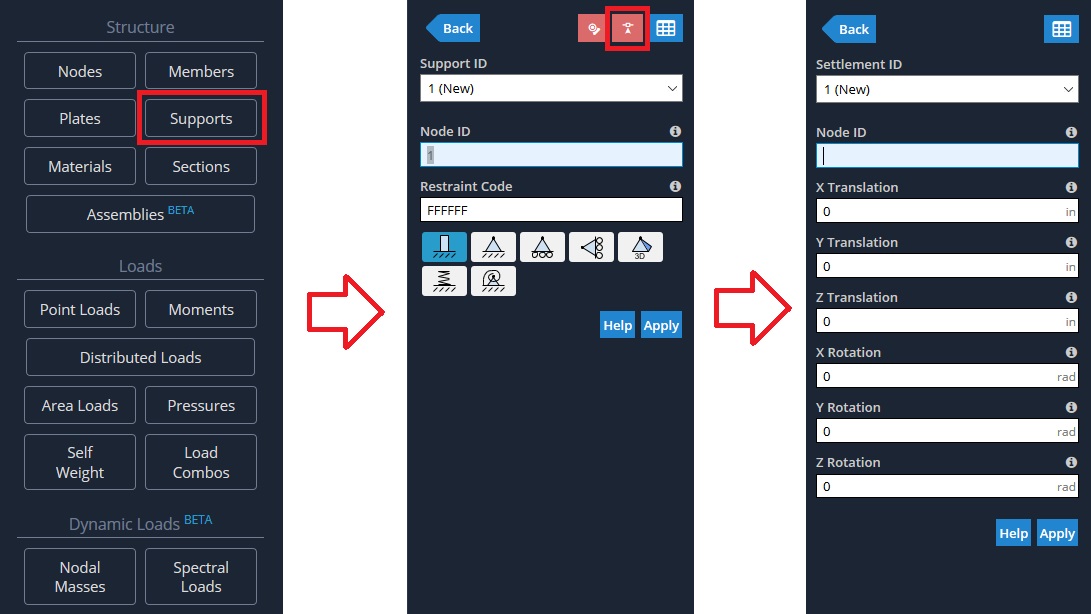
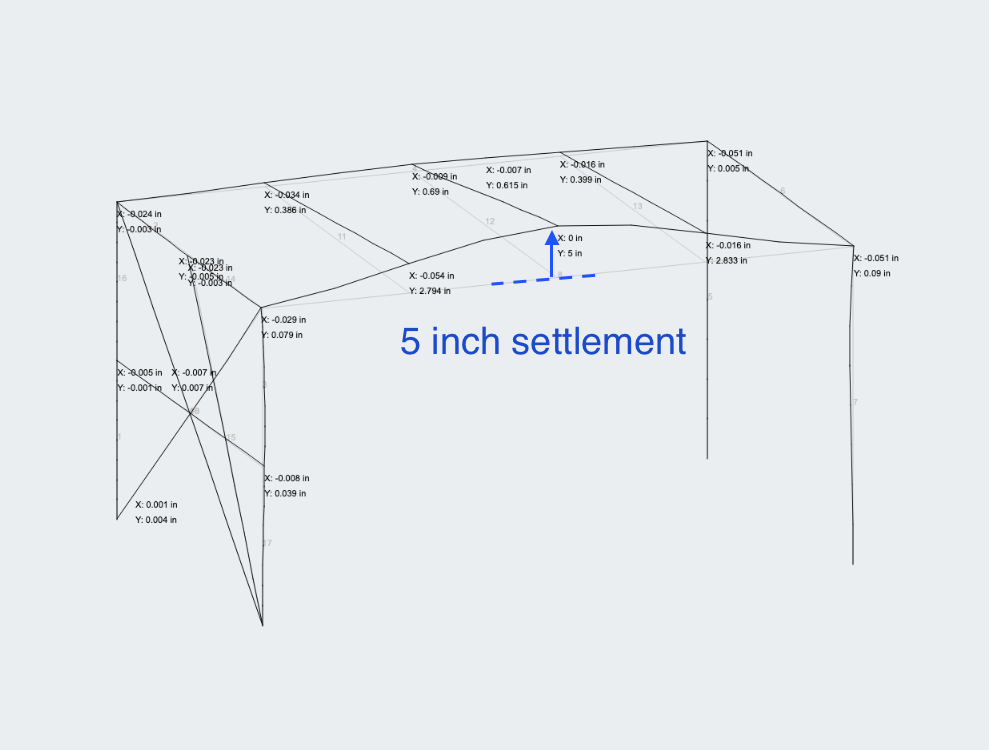
Settlements can be used as a way to define a deflection load or fixed deflection at that location. For instance, you could apply a support and settlement displacement at a midspan of a member and the analysis will apply that displacement at that node location. In the below example, a positive settlement of 5 inches has been added to camber the beam upwards:
Spring Supports
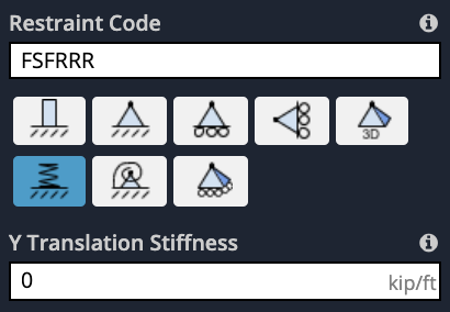
Once the user enters an ‘S” in a particular direction, another input will appear to prompt the user to enter a Stiffness for that particular direction. e.g. if the user enters a Vertical Spring (like the above example) an input for Y Stiffness will appear. The stiffness input is entered as force/distance (kip/ft, kN/m, etc..) which essentially represents how much force is required to compress the spring by a given distance (foot, meter).
The spring stiffness (normally denoted as k) can be calculated in a few different ways (based on Hooke’s Law (F/displacement), or based on the material EA/L) or can be supplied by the manufacturer of the spring support.
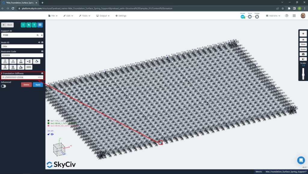
Surface Spring Supports
SkyCiv has a powerful integration of springs for Mat foundations. This will help you include the soil elastic stiffness in your model as spring supports. This soil property (Modulus of Subgrade Reaction) is obtained from the geotechnical reports of the site.
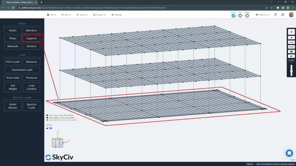
In order to define surface spring supports in SkyCiv S3D, first, you have to select all the plates at the level where the supports will be defined.
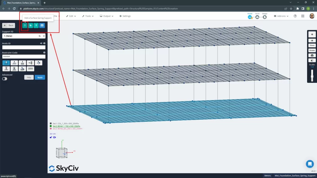
Then, go to the support button and select the option “Add a Surface Spring Support”.
When the prompt window appears, define the “Modulus of Subgrade Reaction” (units of force over volume), which SkyCiv will convert into node springs.
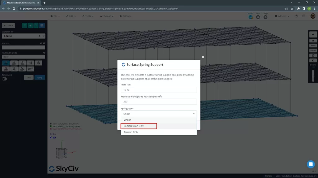
And finally, the software creates a spring support with the equivalent stiffness on each node of the meshed plate.
Inclined Supports
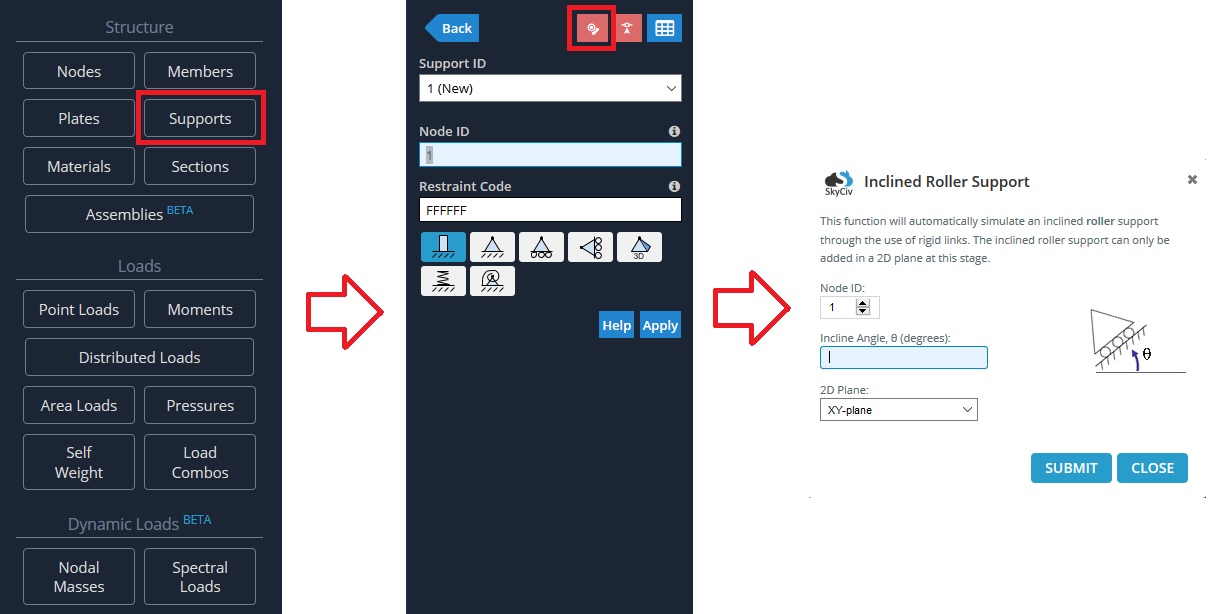
If you have a support that is not parallel with the X-Z plane, you can add an inclined support. These supports are not fully fixed or pinned, but are “roller” supports that are free to move in the rotated plane. The reaction results at inclined supports will be orthogonal to the rotation of the support. You must select a node before clicking on the inclined support button as shown.
To model an inclined support, go to the “Supports” menu, then click on the inclined support button. The Inclined Roller Support popup will appear, input the necessary data.
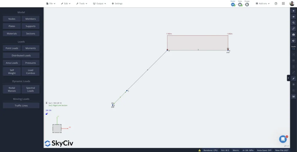
Supports always work in the global axes, so this will introduce a rigid member connected to a support at the angle specified in order to perform the analysis on the member. When solved, the software you can display the inclined reaction in the model.
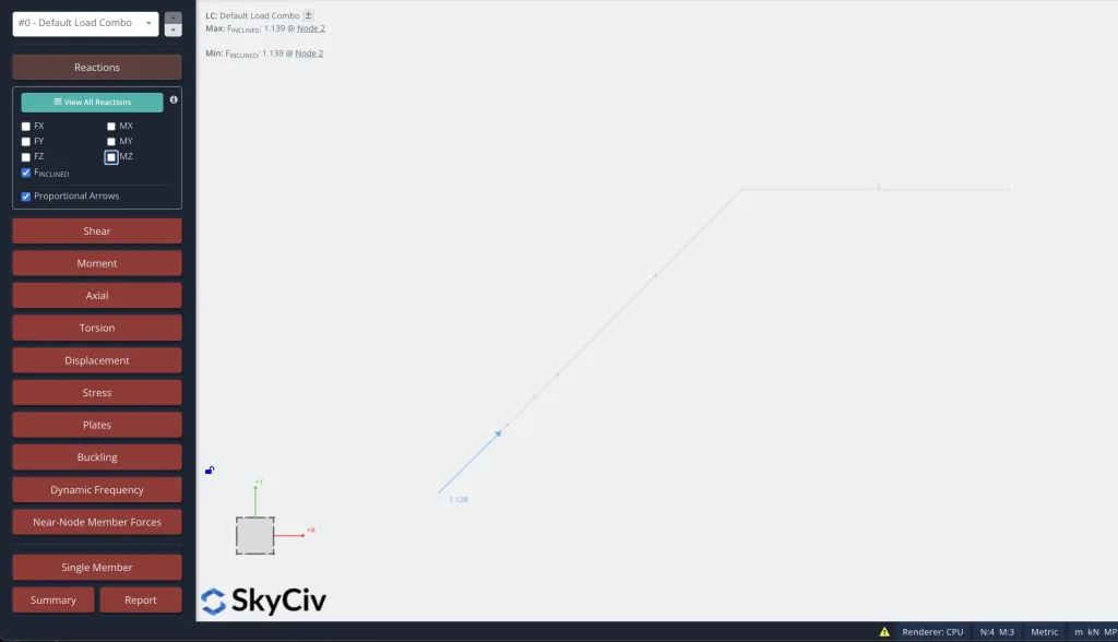
The reactions will be calculated in the usual X,Y,Z global coordinates. However, you can tick on F Inclined to see the equivalent reactions forces at the angle of the support:
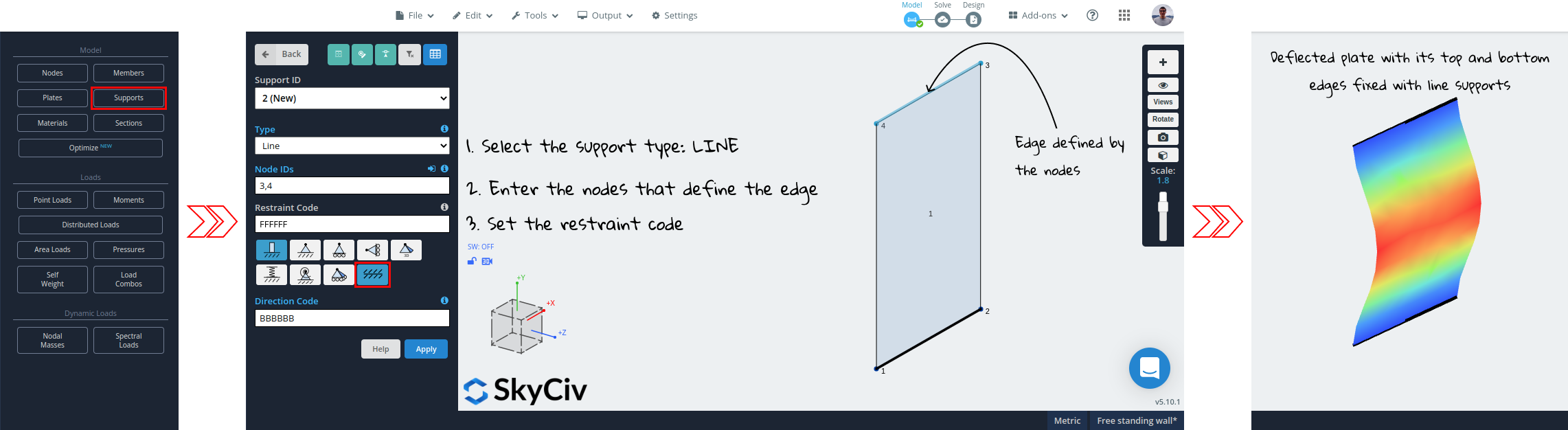
Line Supports
For adding a line support to the edge of a plate, follow the next steps:
- Navigate to the supports view in the left panel
- Select “line” as the type of support (using the dropdown or the icon)
- Type the IDs of the nodes that define the plate’s edge
- Define the six-characters-long restraint code to set if each degree of freedom is fixed (F), released (R) or spring (S)
- Hit Apply
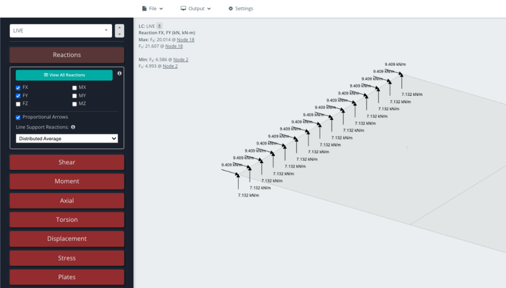
In the results tab, users can pick from three types of linear reactions:
- Nodal Reactions: Displays the actual reaction at each node in the line support. No averaging is performed. Force reactions are in kN and moment reactions are in kN-m
- Point Average: Average the nodal reactions in each line support and display that average value at each node. The average is the sum of forces along the line support, divided by the number of nodes within the line support. Force reactions are in kN and moment reactions are in kN-m.
- Distributed Average: Calculate the distributed reaction over the length of each line support and display that value at each node. The distributed reaction is the sum of forces along the line support, divided by its length. Distributed force reactions are in kN/m and distributed moment reactions are in kN-m/m.
Selecting one of these options (in this example Distributed Average) will show the results of the linear support along it’s length: