Introduction
Greenhouse structures are relatively simple and light structures that are often used in agricultural developments to protect plants from extreme weather conditions, especially during winter season. The selected material is usually steel or aluminum. In this tutorial, we will show you how to model a greenhouse structure using SkyCiv Structural Analysis Software.
Structural behavior
A greenhouse typically consists of horizontal purlins, primary beams, vertical posts, and eventually bracing systems. The purlins are used to distribute the vertical loads as well as the upward and inward wind loads acting on the roof to the primary beams. For this reason, moment connections are typically used to connect purlins and primary beams. The primary beams transfer the vertical and lateral loads to the vertical posts, which act in a similar way as columns in buildings. The posts should be able to transfer the loads to the ground without buckling. In cases of relatively large greenhouses for the stability of the structure as a whole and in order to limit the lateral displacements, bracing systems are often used, composed of truss members (usually in the form of X).
Modeling aspects using SkyCiv
For the numerical modeling of the different structural members, SkyCiv offers a variety of options both for cross-sections and for boundary conditions. Vertical posts are typically pinned at their base (FFFFRR) and continuous at the connection with primary beams on the top (FFFFFF). The diagonal members of the bracing system, if present, are pinned at both ends and therefore can receive only axial deformations. On the other hand, purlins and primary beams can also receive bending moments and shear forces.
This example shows the response of a greenhouse with 30 nodes and 35 members subjected to wind loading in the x direction only (self-weight is excluded). The selected material is structural steel. For the purlins a rectangular hollow section RHS 100 x 50 x 3.0 is used while for the primary beams a section channel and angle sections are used. For the diagonal members, angular sections are adopted. When defining the truss members, the bending moment is released at both ends (FFFFRR) by selecting “Truss” instead of “Frame” below the Member ID textbox.
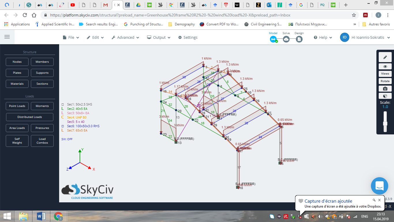
Figure 1: Structural members including end releases and distributed wind loads on the greenhouse.
Results at global and local level
SkyCiv makes it possible to visualize the analysis output both locally in terms stresses and node displacements as well as globally in terms of internal forces. In the following a snapshot of the bending moment diagram is illustrated in the classic diagram form, with which most engineers are familiar. It can be seen that the maximum moment is rather low (0.6 kNm).
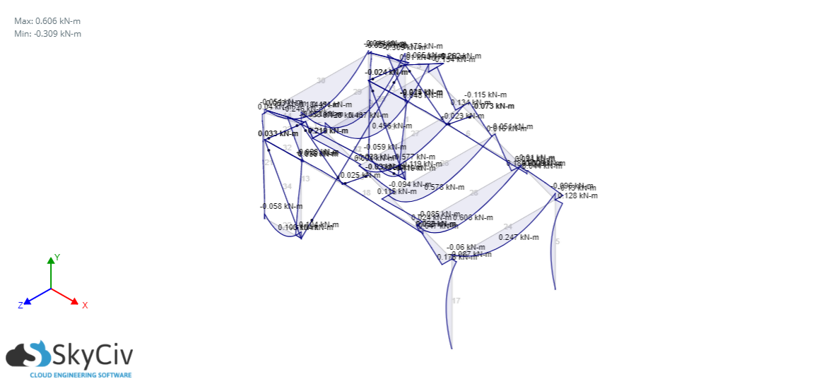
Figure 2: Bending moment diagram of the greenhouse structure.
The following figure shows the deformed shape of the analyzed structure as well as the node displacements in the x direction. Note that the maximum displacement is the resultant of the displacements parallel to x, y, and z directions and is therefore greater that the horizontal node displacement of the frame in the x direction.
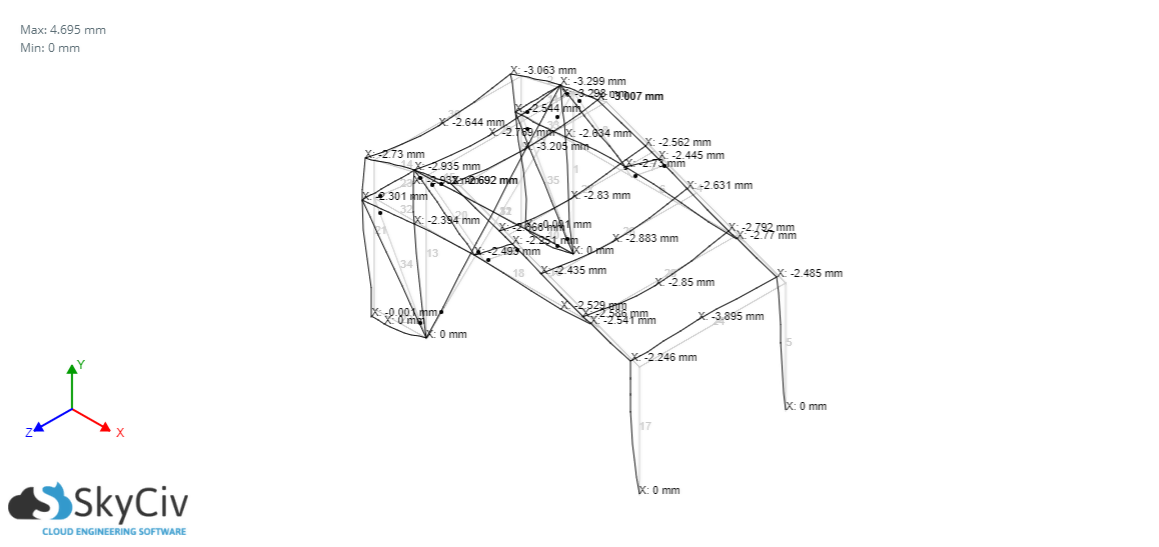
Figure 3: Deformed shape of the greenhouse under wind loads.
In the following snapshot the axial forces acting on the different members can be viewed as arrows. Tension is illustrated in red color (arrows pointing away from the node of interest) while compression is shown in blue color (arrows pointing towards the node of interest). It can be seen that the vertical posts of the rear and the horizontal members connecting the rear face of the greenhouse with the front face are the most loaded members. The diagonal members also receive significant axial forces. It should be noted that members subjected to compression should always be verified for buckling. This too can be analyzed in SkyCiv by running a Buckling Analysis. In this example the maximum compressive load is rather small (8.7 kN).
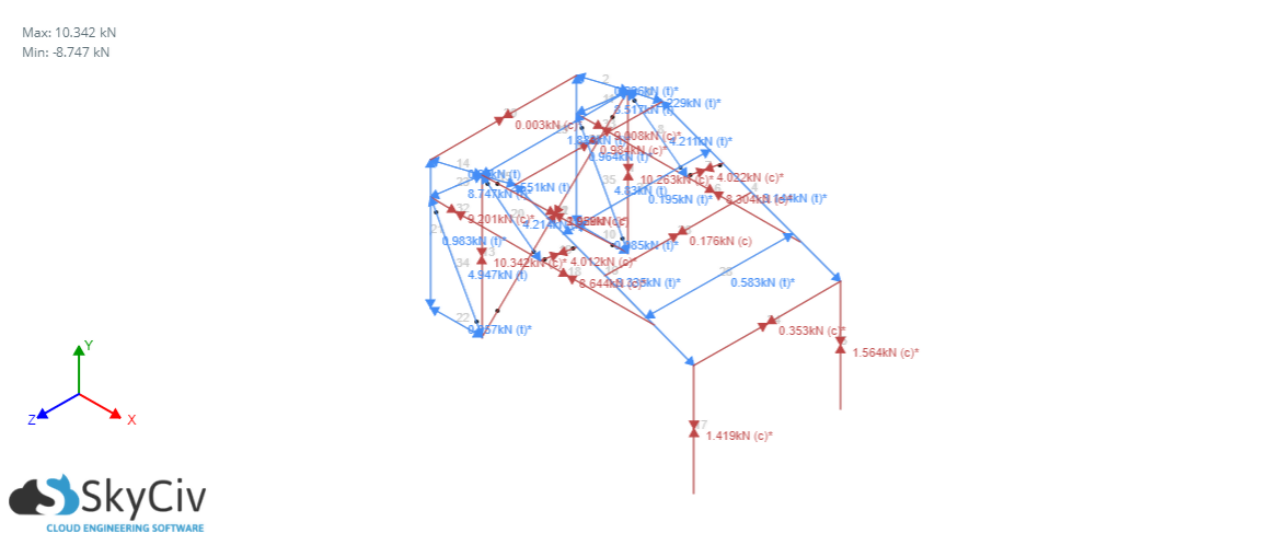
Figure 4: Axial forces acting on the structural members of the greenhouse under wind loads.
This last snapshot illustrates another versatile feature of SkyCiv which is to visualize the structure output in 3D using colors to indicate locations where the maximum values of the plotted factor are attained. Here the stress for bending about the z direction is shown. It can be observed that the purlins are the most heavily stressed members but the maximum stress is 57.7 MPa, which means that structural safety is guaranteed. The user is always free to modify the structural system so that the structure meets all structural and non-structural requirements (for instance available space).
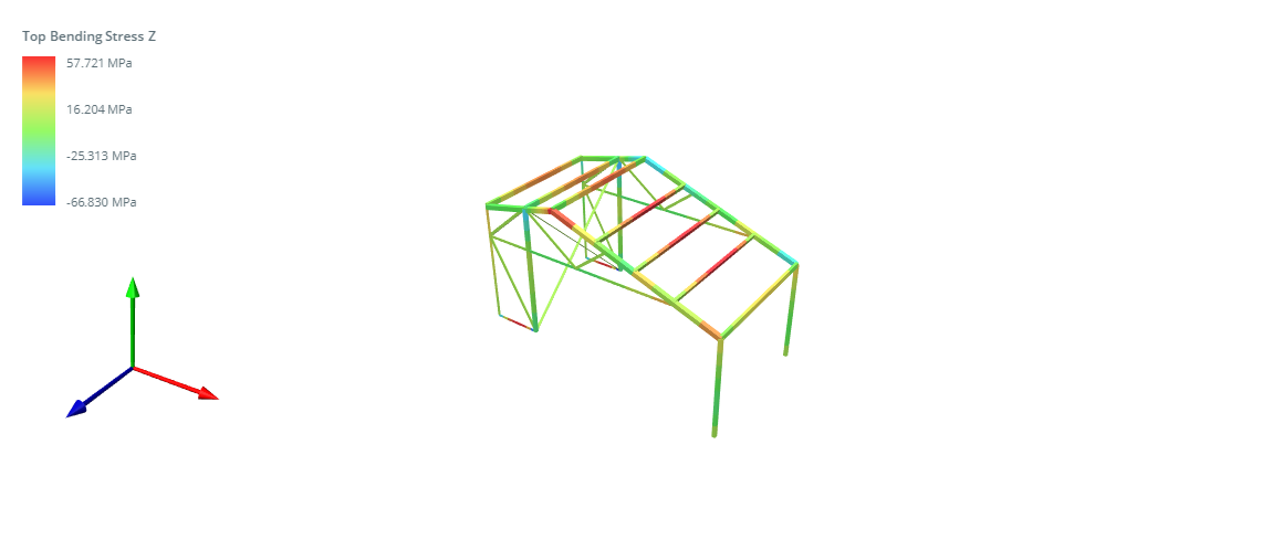
Figure 5: 3D visualization with color of the intensity of bending stresses about z axis.
SkyCiv Structural 3D
I hope this tutorial has helped you understand the process of modeling a greenhouse. Sign up today to start your project!