Composite Beam Design
as per ANSI/AISC 360-16
When it comes to the non-residential multistorey building structures, Composite construction is preferred over purely Steel or RCC Construction. The key of efficiency of composite construction over the other Constructions can be expressed in a simple way. Steel is good in tension and Concrete is good in compression. These are utilized in a way that leads to lightweight beams. SkyCiv’s Composite Design Module/Program is capable of enabling the user to design the composite beams efficiently complying to the provisions of American,European and Australian Standards.
In this article, we will walk you through the Composite Beam Design considering the ANSI/AISC 360-16 design code.
Key Points
- Support for ASD & LRFD
The composite beam program supports both the methods of AISC namely ASD & LRFD. The user can choose the method on the UI as an input and design the beam accordingly.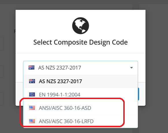
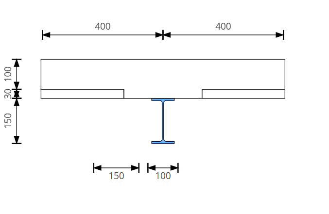
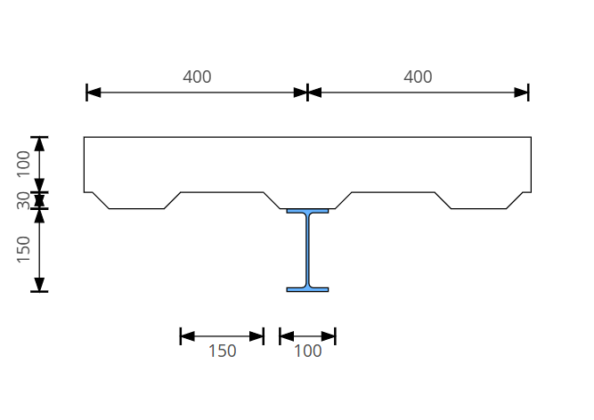
- Design of Beam with any Deck Orientation.
The module performs the design of composite beams either with deck or without deck. The deck orientation having decking angle >20 degrees is considered as “beam with perpendicular deck” whereas the angle < 20 degrees is considered as “beam with parallel deck”.
Decking Angle 45°
Decking Angle 0°
- Moment Capacity
The program considers the case of sagging as well as hogging bending moment capacity estimation.
These capacities are available for various possible options as listed below:
Various deck layouts are possible:
1. No deck
2. Clipped pan parallel to beam
4. Clipped pan perpendicular to beam
5. Corrugated open trough parallel to beam
6. Corrugated open trough perpendicular to beam
7. Re-entrant Corrugated parallel to beam
8. Re-entrant Corrugated perpendicular to beam
- Stress Block Diagrams
Stress block parameters are intelligently calculated by the program for various degrees of shear connection with respect to the PNA position to arrive at the ultimate moment of resistance of the given section. They are represented in a tabular form. Refer fig below
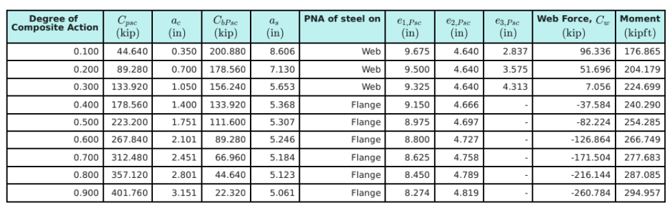
Moment Resistance for Different Degree of Composite actions
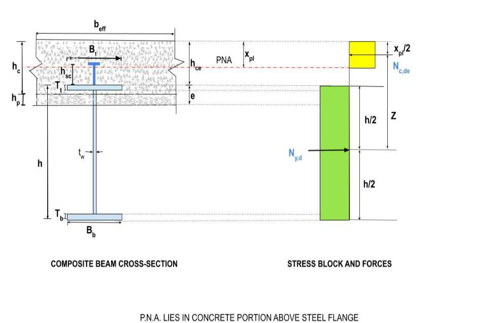
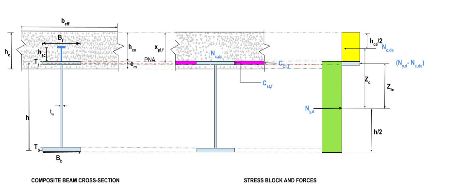
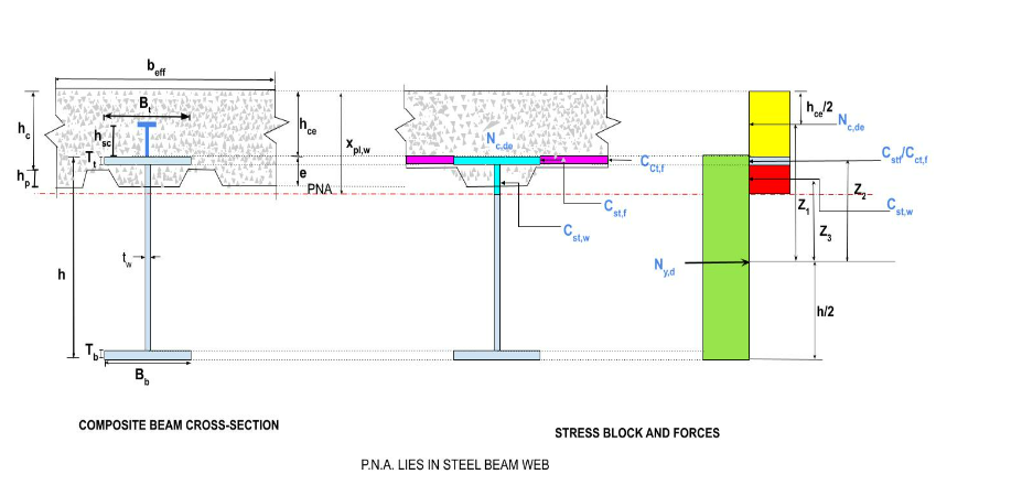
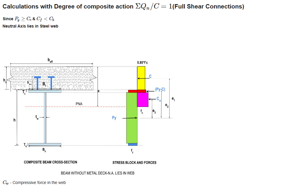
3 Possible cases of PNA position for a case of beam without deck are shown viz
i) PNA lies in CONCRETE SLAB
ii) PNA lies in STEEL FLANGE
iii) PNA lies in STEEL WEB
- Relationship between Degree of Shear Connection and Moment Resistance Ratio
Bending moment capacity calculation is shown for various degrees of shear connection via UNIQUE GRAPH so that user can:
i) evaluate the moment capacity for present state of shear connector
ii) forecast the moment capacity for a different set of shear connector data
Refer fig below
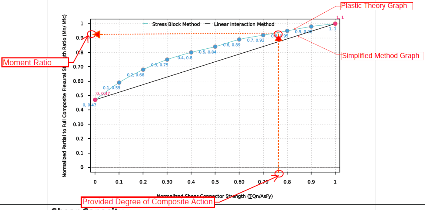
Relationship between Degree of Shear Connection and Moment Resistance Ratio
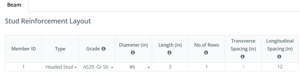
How to use the Graph and Table of Partial Composite action?
Refer to the Shear Studs Specifications i.e., Diameter & Spacing of Stud from the SkyCiv Report you will get after using the program and running the Design Check. Sample Snapshot of the specification is as shown below.
-
- Select the value of “Degree of Composite action” On X-axis.
- Get the respective value of Moment resistance ratio on Y-axis of graph.
- Get the value of Moment Resistance for respective degree of Composite action from Fig2.
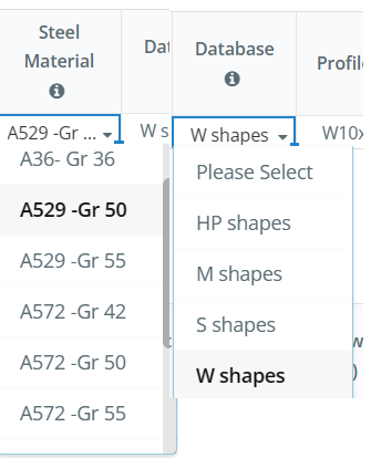
- Material Grades:
The program can evaluate the design for various material grades as shown below.
- Classification of Steel Section
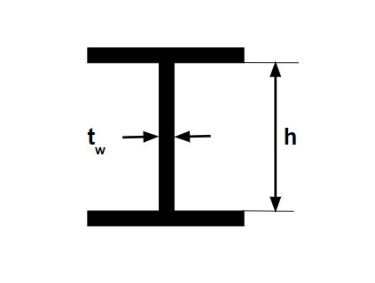
The Moment Capacity Calculations of the Composite Beam depends on the Classification of the Steel Beam Cross-Section Element.
a. Calculate the ratio h/tw
where,
h = the clear distance of web between the flanges
tw =thickness of web
Compare the ratio with the values in Chapter B, Table B4.1b
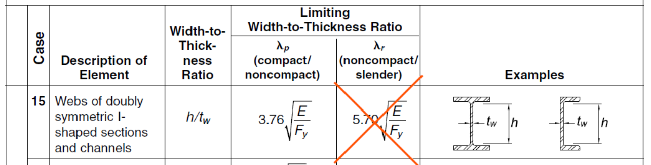
c. Determine the classification of the steel section element.
d. It is to be noted that only Compact and Non-Compact steel sections are used. Cross-sections having slender elements are avoided in Composite Beams.
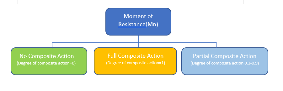
- Moment Capacity:
Designing the composite beam for strength criteria involves calculation of moment capacity. The module is capable of evaluating the sagging moment capacity of a beam as a case of Simply Supported beam. There are the three possibilities that need to be considered while designing the Composite Beam. The program considers all the three possibilities and provide the detailed calculations for each of the cases.
-
- Full Composite Action (Full Shear Connections)
The moment capacity is calculated considering that the entire horizontal shear is transmitted by the shear connectors.
-
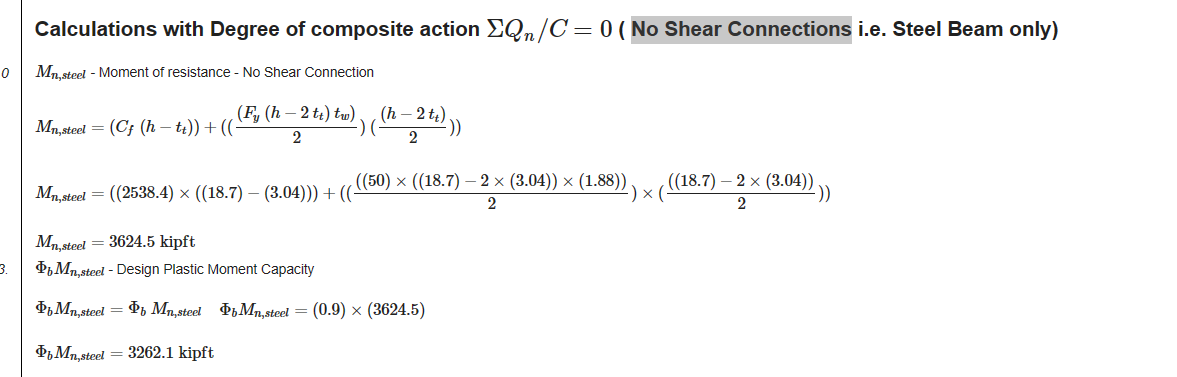
- No Composite Action (No Shear Connections)
The moment capacity is calculated for the steel beam only for this case. This case happens to occur during a short period of time during construction.
-
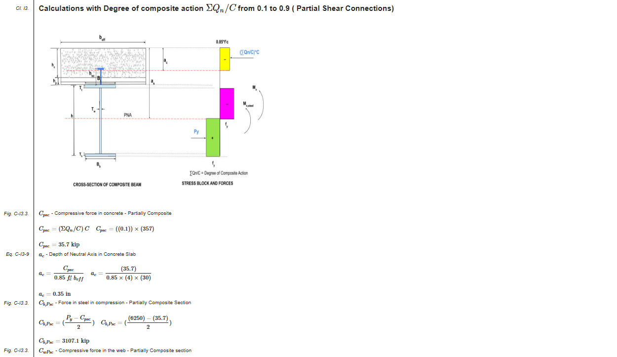
- Partial Composite Action (Partial Shear Connections)
Moment capacity is calculated considering the partial transfer of horizontal shear through shear connectors. The appropriate selection of degree of shear connection can provide the highly efficient use of Steel and Concrete properties.
- Shear Capacity:
Shear Capacity is calculated for transverse shear as well as longitudinal shear. 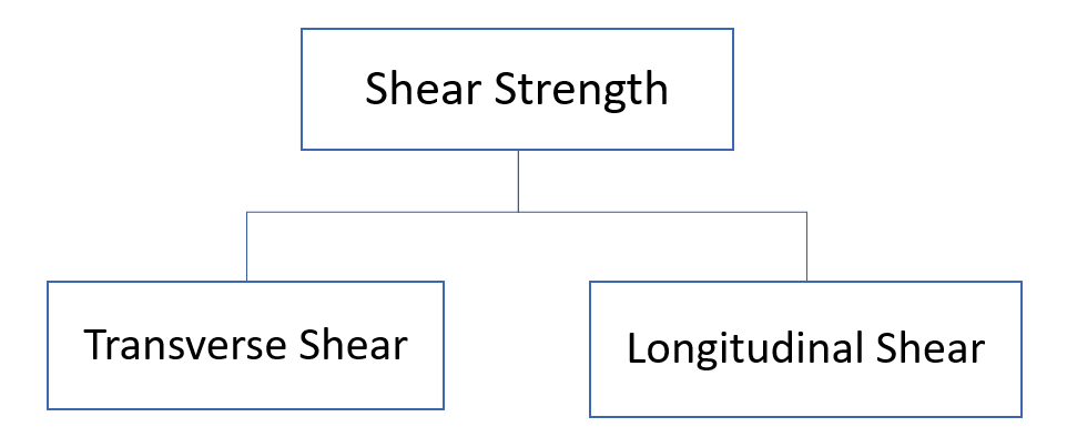
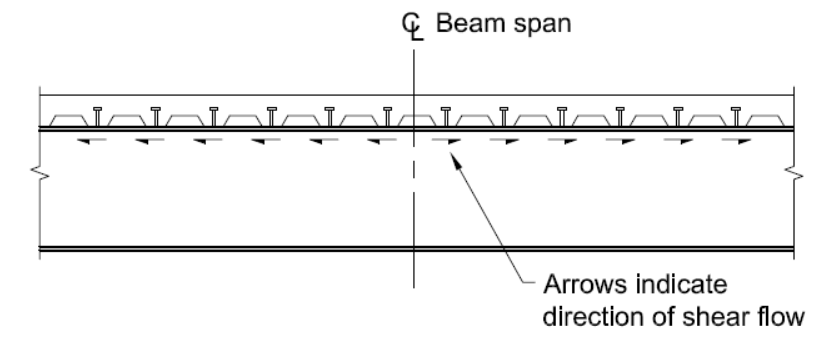
Longitudinal Shear:
-
- The entire Longitudinal shear at the interface between concrete slab and steel beam for simply supported beams is assumed to be transferred by the steel headed studs or steel channel anchors.
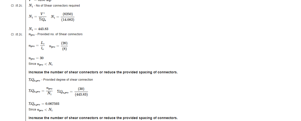
- The Partial Composite action evaluation steps can guide the user about optimization Steel Anchors based on the criteria of horizontal shear resistance.
The step-by-step calculations also gives the required and provided number of shear connectors along with the checks against them with proper message to the user as shown below
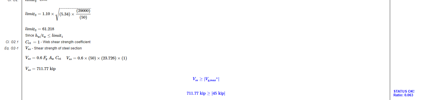
Transverse Shear:
The vertical shear resisted by the given cross section is evaluated based on contribution from structural steel only (as per AISC 360-16). The detailed calculations gives the Transverse shear strength as well as the comparison of the same with the input to determine the Utility ratio and the status as shown below.
- Testing and Validation:
We have taken the outputs from our program for the 9 various cases and validated them with the tools available in the market for the Composite Beam Design.
Here is the list which covers all the cases:
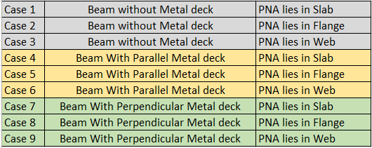
Here is the comparison of results presented in graphical format:
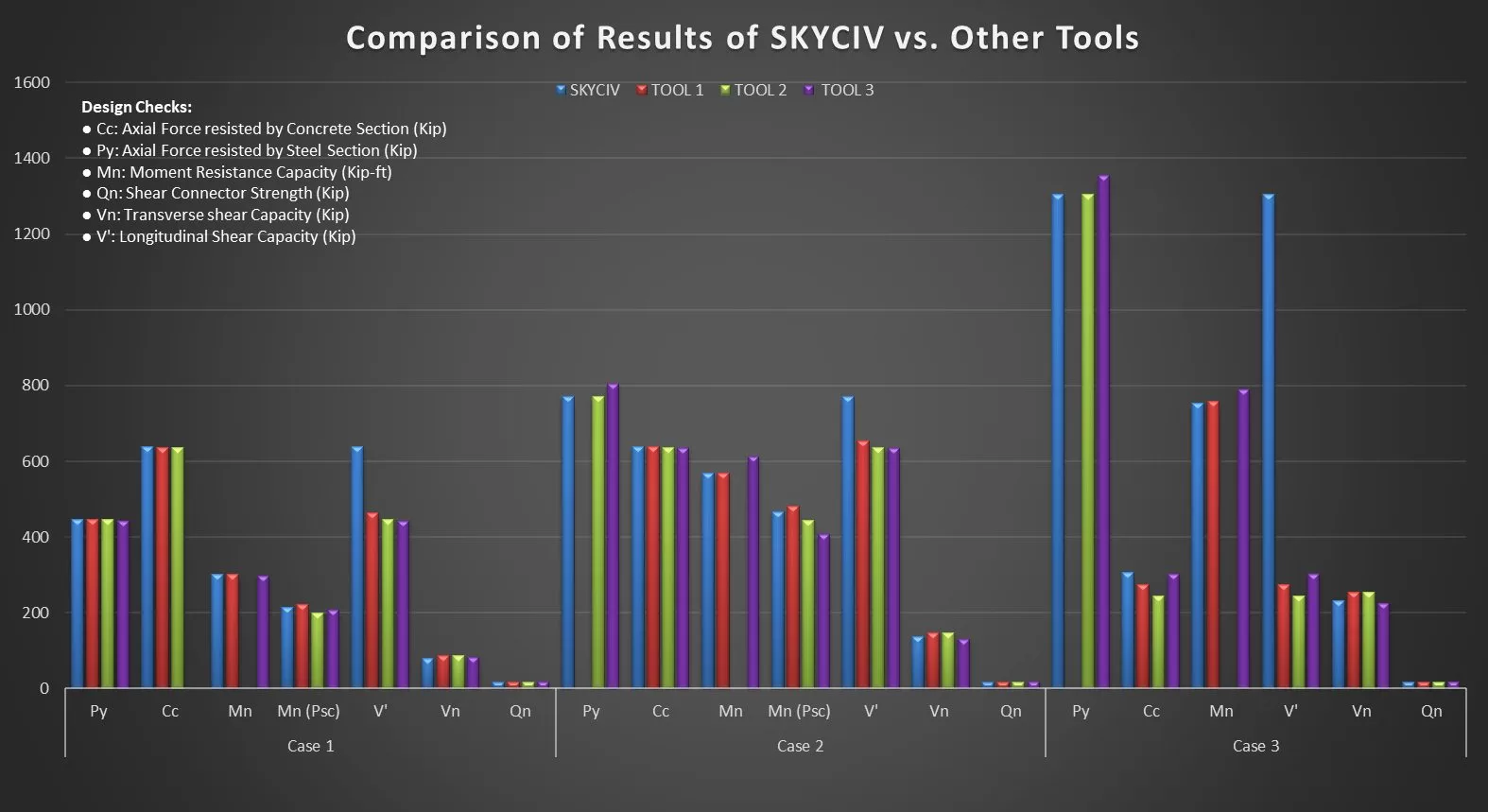
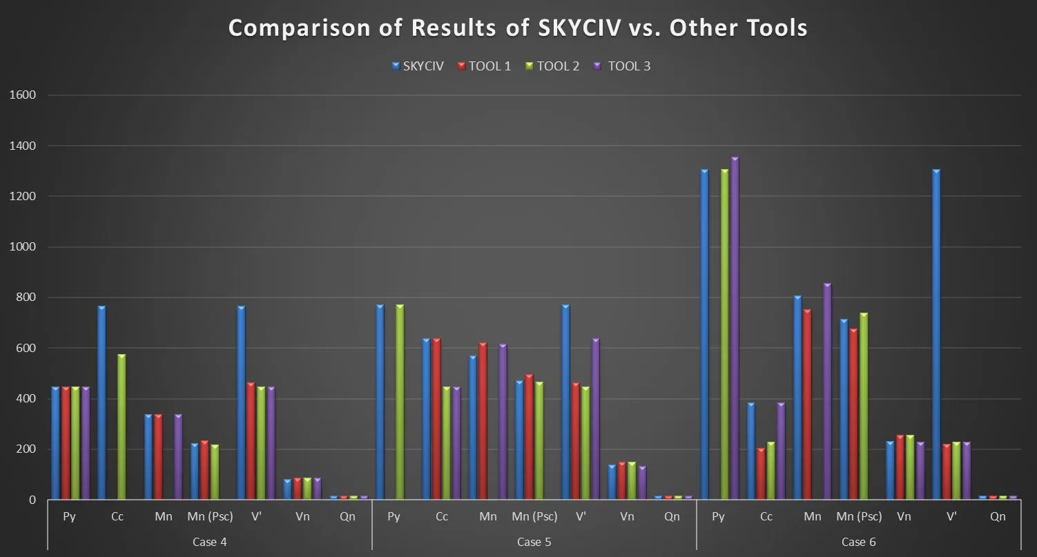
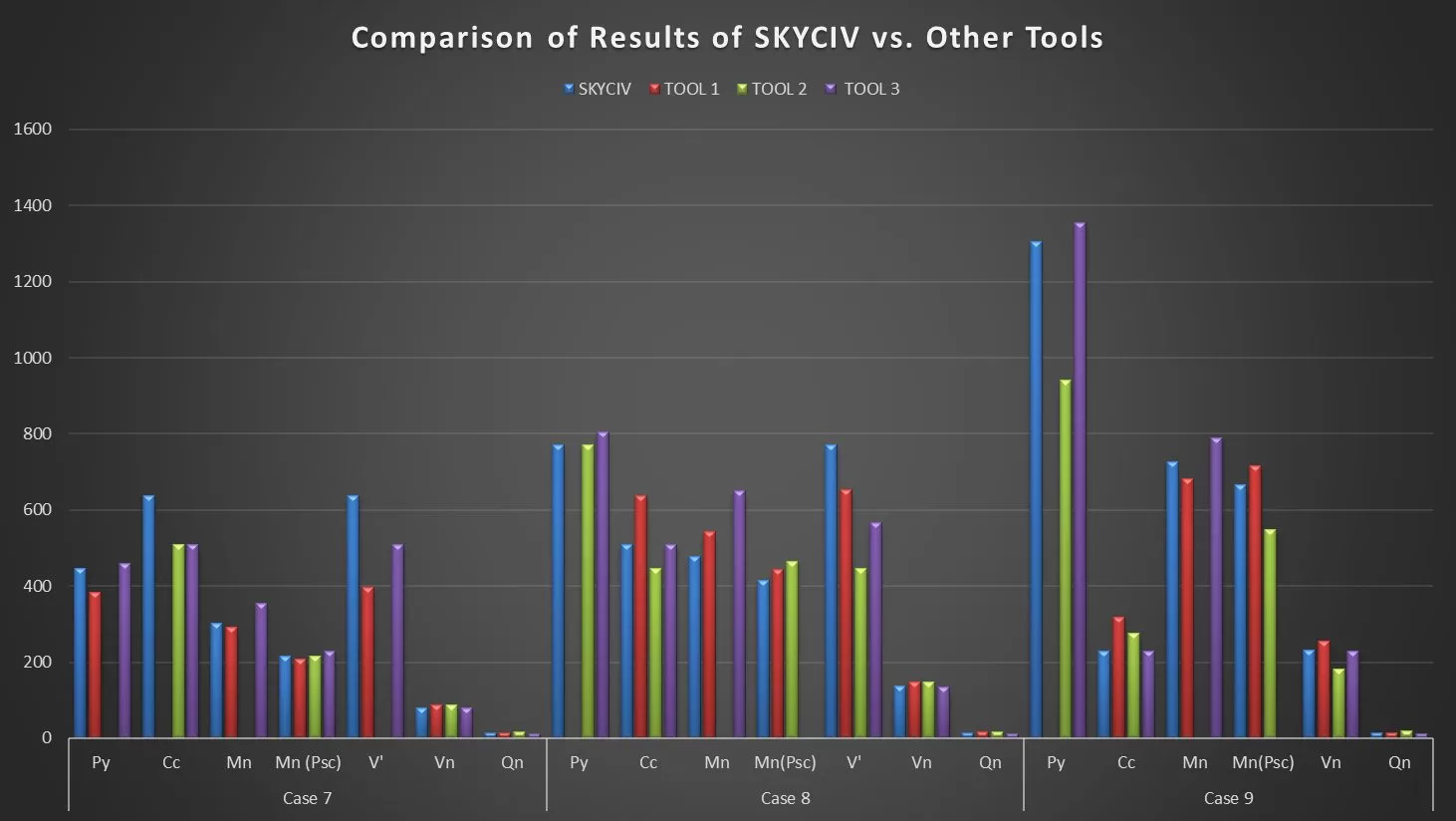
The testing is carried out to verify the technical considerations made, sections/clauses applicable, calculations carried out. Below are the snapshots of the comparison of results of SkyCiv and other tools.