Using the SkyCiv Load Generator in NBCC 2015 Wind Load Calculations
To calculate the wind load pressures for a structure using SkyCiv Load Generator, the process is to define first the code reference. From there, the workflow is to define the parameters in Project Tab, Site Tab, and Building Tab, respectively. However, free users can only use the calculation for a gable and open pitched/duopitched roof for a maximum of 3 solves per week. With a Professional Account or by purchasing the standalone Load Generator module, you can use all the features of this calculation as long as you want You can purchase the standalone module thru this link.
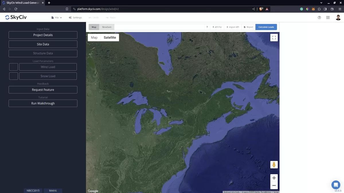
Figure 1. SkyCiv Load Generator UI.
Site Data
Users can get the hourly wind pressure by location any time from the SkyCiv free wind speed map database. Using NBCC 2015, the first step is to define the Recurrence Interval to either 10 years or 50 years to obtain the appropriate hourly wind pressure, q, from the database. Then, select the Limit State whether you are considering the Service or Ultimate Limit State, and the Importance Category of the structure depending on its occupancy. These parameters are used in obtaining the Importance Factor, Iw. After these steps, you just need to put the address located in Canada and the module will search for the location from Table C-2 of Appendix C of NBCC 2015. The corresponding Hourly Wind Pressure and other location-specific data will be obtained from the database. You can also override the basic wind speed to get a more appropriate design wind pressure.
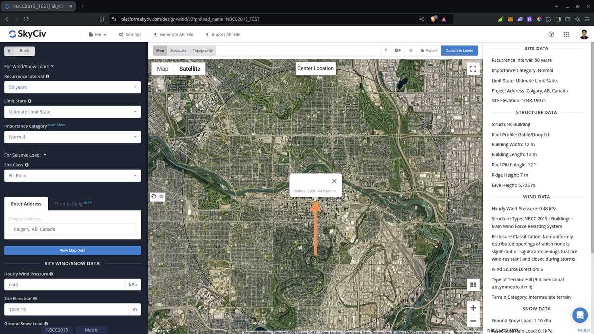
Figure 2. Site data of SkyCiv Load Generator.
SkyCiv has digitalized the map as per the paperback standard. This means, you can simply enter in the site location and the software will automatically pull the wind speeds based on this input. The software will use our internal interpolator to calculate values between the contours, to ensure accurate wind speeds are used in your designs.
Site Input Parameters for Wind Load Calculation
Recurrence Interval – The annual probability of occurrence: (10-year and 50-year return period) of the wind pressure
Limit State – options are Ultimate Limit States (ULS) and Serviceability Limit States (SLS)
Importance Category –for calculating the Importance Factor Iw based on Table 4.1.2.1.
Project Address – Used for getting the nearest wind speed based on the wind region and country
Hourly Wind Pressure – the hourly wind pressure to be used in calculating the design wind pressure. This is automatically determined based on Project Address and can be modified by the user
Once the parameters above are completed, we can now proceed to the Structure Data section.
Structure Data
The structure data and the wind and snow parameters are separated into different sections. You need to define first the Structure you are analyzing. Currently, only Building structure is supported in NBCC 2015.
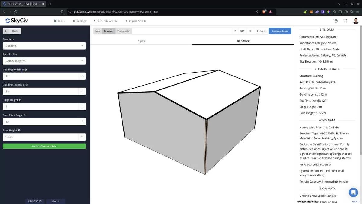
Figure 3. Structure data input for buildings.
For building structure, we need to fill the structure dimensions as shown in the building figure above. The option for the roof profiles are as follows:
- Gable/Duopich
- Monoslope/Monopitch
- Hip
For free users, only Gable roof is available for Building. Once you have completed all the structure data inputs, you can visualize the structure by clicking the 3D Render at the right side. In addition, note that the building length is defined as the dimension parallel to the wind direction (as shown in arrow) and the building length is perpendicular to the wind direction.
Structure Input Parameters for Wind Load Calculation
Roof Profile – Used in pressure coefficient values based on the selected roof profile and roof pitch angle
Building Length – the dimension parallel to the wind direction as defined in NBCC 2015. Used in calculation of pressure coefficients
Building Width – the dimension perpendicular to the wind direction as defined in NBCC 2015. Used in calculation of pressure coefficients
Ridge Height – the dimension of the structure from ground to the roof apex.
Roof Pitch Angle – the roof slope in degree. Used in calculation of pressure coefficients
Eave Height – the dimension of the structure from ground to the roof eaves. This is automatically calculated upon completion of Ridge Height and Roof Pitch Angle.
Once the parameters above are completed, we can now proceed to the Wind Load Parameters section.
Wind Data
To proceed with our wind load calculation, we need to check the checkbox first beside the Wind Load button. By default, this is checked when the site wind data has been defined.
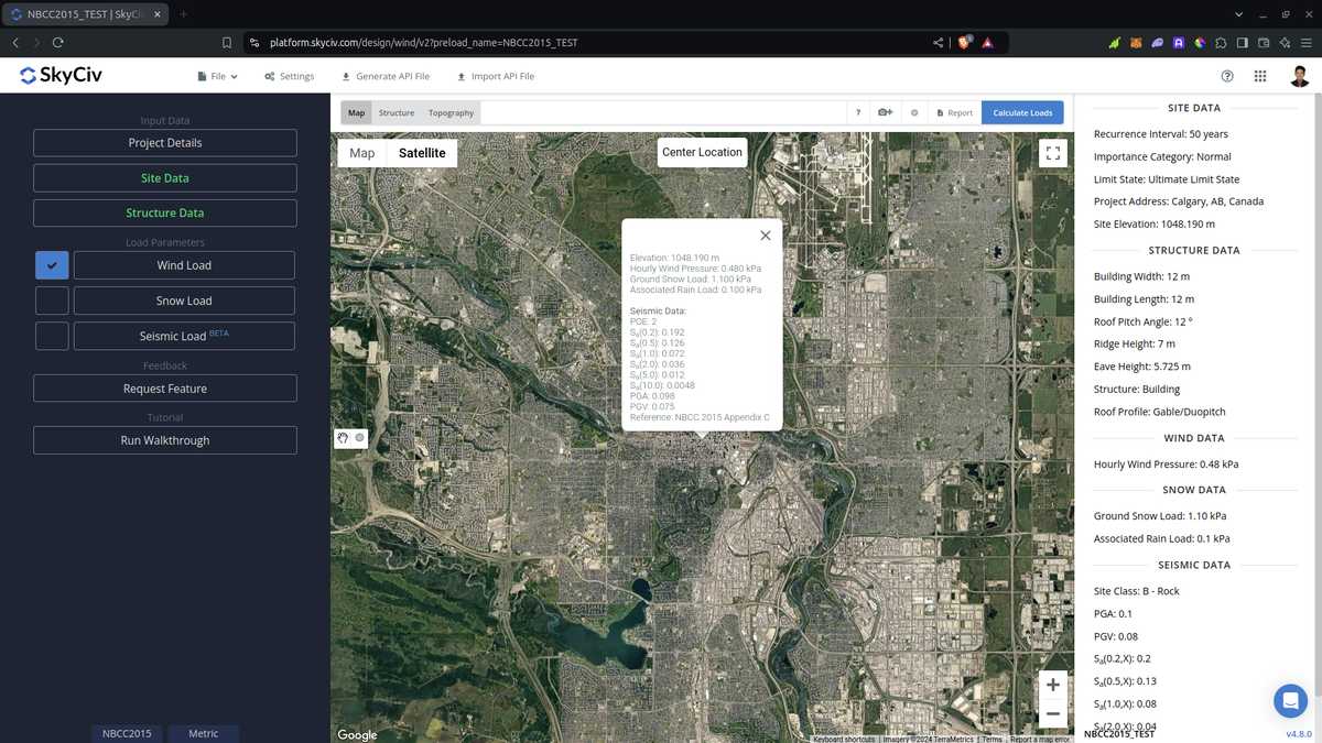
Figure 4. Checkbox for Wind Load Data.
The next step, is to define the Wind Source Direction the corresponding Terrain Category of the upwind area. The Wind Direction parameter is used in obtaining the upwind (left side) and downwind (right side) ground elevations to calculate for Topographic Factor, Ct. In addition, the Terrain Category is used in determining the Exposure Factor Ce.
From version v4.7.0, Intermediate terrain option was introduced to calculate the Exposure Factor \( C_{e} \) for intermediate terrain roughness on the upwind side. You just need to fill up the Upwind Extent of Rough Terrain value. This is the length of rough terrain, as defined in Section 4.1.7.3(5) of NBCC 2015, measured from the structure location. If this distance is greater than or equal to 1km or 20 times the structure height, whichever is greater, the terrain can considered as Rough Terrain, and if the distance is less than 50 m, it is considered as Open Terrain. Otherwise, it will calculate the interpolated Exposure Factor \( C_{e} \) as per Section 4.1.7.3(5). With regard to this, new tools are introduced – Measure Distance and Distance Radii tools.
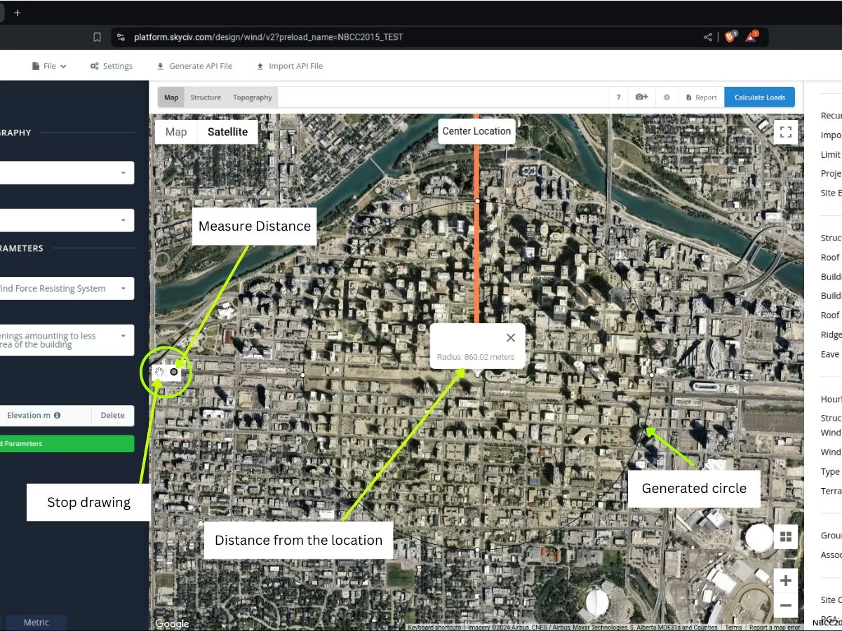
Figure 5. Distance measuring tools added to SkyCiv Load Generator.
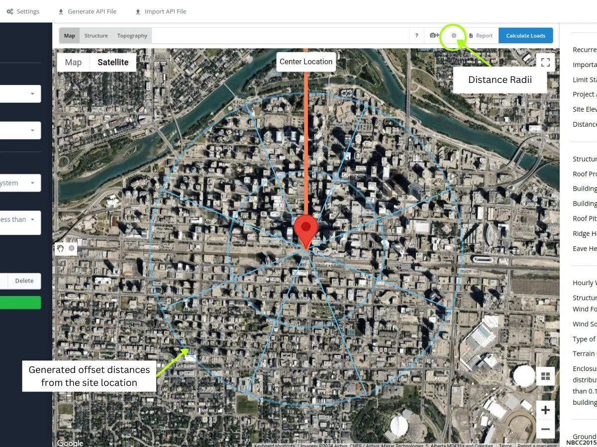
Figure 6. Distance Radii tool added to SkyCiv Load Generator.
The Measure Distance tool is used for generating a circle from a clicked point in the map and show its radius in meters. This way, you can measure the distances from the location being analyzed the certain locations. This can be used in determining the value for the Upwind Extent of Rough Terrain. On the other hand, the Distance Radii is introduced so users can draw circles with specified distances from location for each wind source category. Using this for NBCC 2015, you can put values of 50m and 1000m (or 20 times the structure height) as these are the criteria for quickly determining the Terrain Category for each wind source direction. That is, if the rough terrain is still visible beyond the 1000m (or 20 times the structure height) circle, therefore, the terrain can already considered as Rough Terrain. If the rough terrain is only visible inside the smaller distance circle (50m radius), then the terrain category is Open Terrain. Otherwise, if the rough terrain length is in between these distance circles, you will need to select the Intermediate Terrain in the Terrain Category and measure the rough terrain length using the Measure Distance Tool. To edit the radius of the Distance Radii, just go to the Settings and put a comma separated value of the radii in meters.
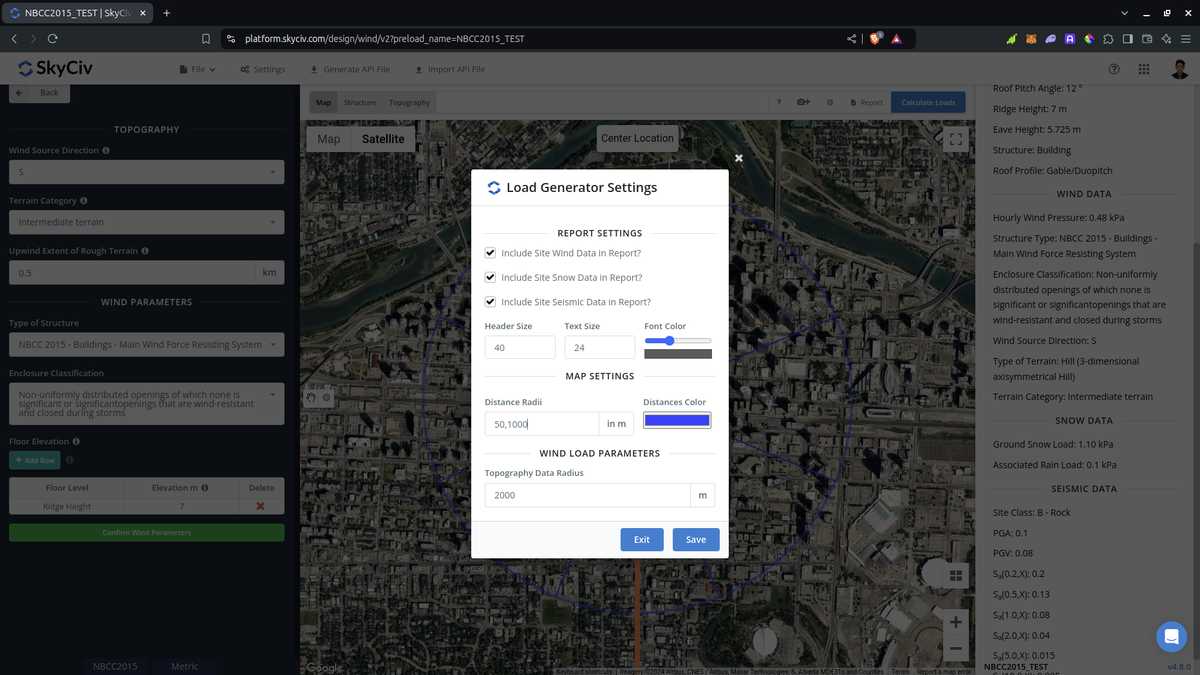
Figure 7. Option in settings to edit the distances for the Distance Radii tool in SkyCiv Load Generator.
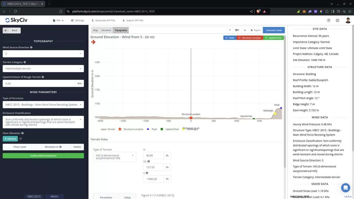
Figure 8. Elevation Data from Google Maps for upwind (left) and downwind side (right).
Topography Input Parameters
Wind Source Direction – used to obtain the elevation data on a specific direction section of the area. These elevation data are used in determining the Topographic Factor, Ct
Type of Terrain – Options to select Flat, Hill, Escarpment, Ridge
H – Height of obstruction/terrain. For type of terrain is set to option other than Flat terrain, this is used in calculating the Topographic Factor, Ct
Lh – Horizontal distance from peak to the middle height of the obstruction. For type of terrain is set to option other than Flat terrain, this is used in calculating the Topographic Factor, Ct
x – Horizontal distance of structure to the peak of the obstruction with the peak as the point of reference. For type of terrain is set to option other than Flat terrain, this is used in calculating the Topographic Factor, Ct
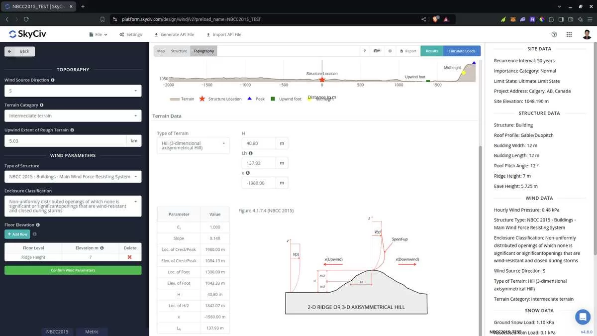
Figure 9. Topography Parameters for NBCC 2015.
Wind Input Parameters for MWFRS
Type of Structure – Required to be set to NBCC 2015 Buildings – Main Wind Force Resisting System (MWFRS)
Enclosure Classification – Options are: Uniformly distributed small openings amounting to less than 0.1% of the total surface area of the building; Non-uniformly distributed openings of which none is significant or significantopenings that are wind-resistant and closed during storms; and Large openings likely to remain open during storms. Used in obtaining the internal pressure coefficients Cpi
Floor Elevation – Since the wind pressure acting on the windward is parabolic in nature, this is used to approximate this pressure by assigning multiple rectangular pressure acting on the wall in between the level
Figure 10. Wind Parameters for NBCC 2015 MWFRS.
Wind Input Parameters for Components and Cladding
Type of Structure – Required to be set to NBCC 2015 Buildings – Components and Cladding
Enclosure Classification – Options are: Uniformly distributed small openings amounting to less than 0.1% of the total surface area of the building; Non-uniformly distributed openings of which none is significant or significant openings that are wind-resistant and closed during storms; and Large openings likely to remain open during storms. Used in obtaining the internal pressure coefficients Cpi
Wind Blockage – For calculation of GCN for open roof profiles
Effective Area of Wall Cladding – Can be a comma-separated value (i.e. 23,44,20) for multiple effective wind area. Used in calculating the design wind pressure for wall cladding or components
Effective Area of Roof Cladding – Can be a comma-separated value (i.e. 23,44,20) for multiple effective wind area. Used in calculating the design wind pressure for roof cladding or components
Cladding Pressure considered? – Option to include/exlude internal pressure for the component/cladding
Floor Elevation – Since the wind pressure acting on the windward is parabolic in nature, this is used to approximate this pressure by assigning multiple rectangular pressure acting on the wall in between the level
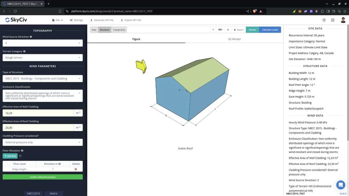
Figure 11. Wind Parameters for NBCC 2015 Components and Clading.
After all these parameters are defined, the next step is to click the Calculate Loads on the upper right side of the UI.
Results
The results of the calculation are shown as follows:
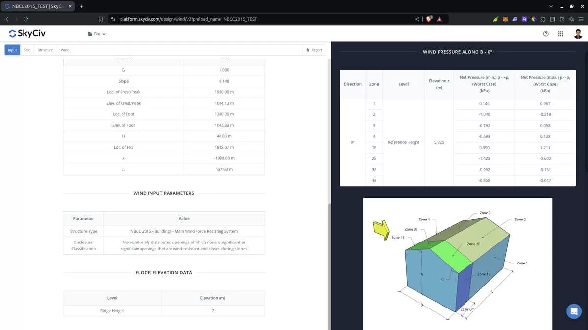
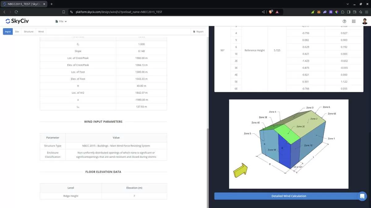
Figure 13. Wind results for Building – Components and Cladding
The summarized results are shown on the right side of the screen.
Detailed Calculation
The detailed wind load calculations can be accessed only by Professional account users and those who purchased the standalone load generator module. All the parameters and assumptions used in the calculation are displayed on the report to make it transparent to the user. You can download a sample detailed calculation thru the following links:
NBCC 2015 MWFRS
NBCC 2015 Components and Cladding
For additional resources, you can use these links for reference: