A guide on how to run a response spectrum analysis on a low-rise steel building
General description and example definition
In zones of seismic activity, construction codes such as ASCE-07 establish seismicity in terms of inertial forces. There are two main approaches to obtaining these forces, static and dynamic. This article is focused only on dynamic forces. If you need to learn how to calculate using the static procedure, we recommend you to read these articles: SkyCiv Seismic Loads Generator and SkyCiv Fully Worked Example of ASCE 7-16 Seismic Load Calculation using Equivalent Lateral Force Procedure.
A Response Spectrum Analysis (RSA) is a linear (strains directly related to stresses) dynamic procedure that uses a structure’s natural vibrations properties in order to obtain the maximum force generated in a motion seismic event. Due to this motion being transferred from ground supports to the full structure, inertial forces will be developed, that is, as Newton’s second law says, Force = mass * acceleration. The source mass is taken from the material building and the level of acceleration has to be defined by the Code. Feel free to check a previous SkyCiv article about RSA: Introduction to Response Spectrum Analysis with SkyCiv S3D.
The following image shows a structural model rendered which consists of a low-rise steel building. The lateral resistance is provided by two different structural systems along the main directions in the plan: concentrically braces frame for longitudinal and moment resistant frames for transverse.
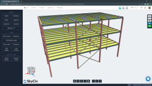
Figure No.1. Rendered Tridimensional Model.
Model creation in SkyCiv S3D
You can go through the following steps to create a model and be able to run an RSA. (For more detailed tutorials regarding modeling, go to our SkyCiv documents: SkyCiv S3D Getting Started)
- Plan and height dimensions. The building has three and two spans in longitudinal and transverse directions, respectively. In elevation, it has three story levels.
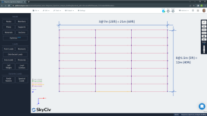
Figure No.2. Plan dimensions.
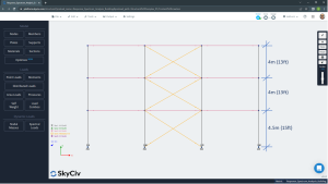
Figure No.3. Story level definition.
- Lateral force resisting systems. To follow good practices in steel structure configuration, it is needed to use accordingly design code recommendations. In this article, we define braced frames along the longitudinal direction (“X”) in which all structural elements have to be connected as a pinned joint. Braces are hollow structural shapes (HSS) commonly square types. For the short direction (transverse) we have established moment-resistant frames considering the capacity to transfer flexural moments between elements through their nodes. For these latter frames, beams and columns are W steel shapes. It’s very important in this structural configuration to assign adequate supports at the column’s base, to correctly catch up with the behavior wanted.
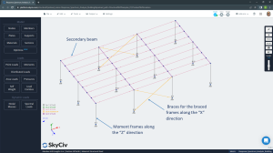
Figure No.4. Braced and resistant moment frames definition.
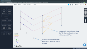
Figure No.5. Supports releasing “Z” rotation degree of freedom.
Braced frames need to accommodate rotation to develop only axial forces (tension or compression). Moment frames need fixed supports at least in their plane. The way to accomplish both requirements is by assigning a fixed degree of freedom for displacement and rotation in each direction (“x”, “y”, “z”) with the only exception of releasing the rotation along the “z” axis. The restraint code to apply is “FFFFFR”; the first three characters for linear displacement and the last three for rotation.
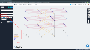
Figure No.6. Group of supports and restraint code assignment.
Floors using Rigid Diaphragms
It is recommended to define rigid diaphragms to reduce the number of degrees of freedom to three per level, two for translational displacement and one for the rotation in the plan.
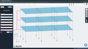
Figure No.7. Rigid diaphragms at stories.
How a rigid diaphragm constraint works is it creates a master node of reference, commonly named “Center of Mass (CM)” and links to the nodes using Rigid Links. One simple definition is the point or node in a system at which the whole mass may be considered as concentrated. For seismic loads, lateral forces are applied to the CM.
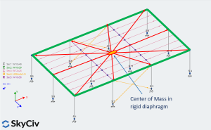
Figure No.8. Master and slave nodes in a rigid diaphragm.
The complete geometric model is shown in the figure below.
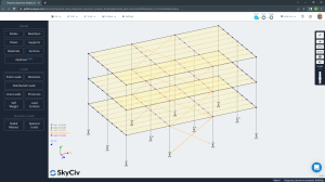
Figure No.9. 3D view of the completed model.
Adding static loads to your model
Construction codes define the loads and the way a combination of them is considered. In this article, only gravitational and lateral forces will be defined.
-
- Gravitational loads: self-weight, superimposed dead and live loads.
- Lateral loads: linear dynamic seismic forces from response spectrum analysis in each plan direction.
To define self-weight load, look at the left ribbon and select in the loads section the option “Self-weight”, then turn on clicking the button “ON”. Next, assign a value of -1 in the vertical direction (in this case is Y-axis Gravity) and finally go to apply button to create this load case.
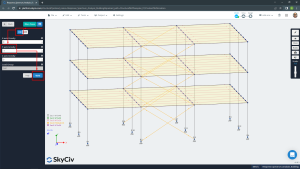
Figure No.10. Self-weight case load definition.
A similar procedure as we did before for self-weight load is required to assign and create user gravitational loads:
- Select “Area Loads” from the Loads section.
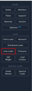
- Select the four corner nodes from a particular floor plate to define the area load perimeter, then assign the pressure magnitude, 2.5 kPa for superimposed and 2.o kPa for live loads. Feel free to give names as you consider convenient for each load case.
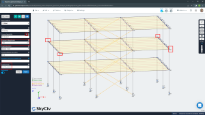
Figure No. 11. Corner plate nodes selection to create area loads.

Figure No. 12. Area loads: Superimposed dead (2.5kPa) and live loads (2.0kPa).
- Go to the visibility settings located on the right ribbon and select “Equivalent Area Loads” to watch the distribution of area loads in every secondary beam in proportion to their tributary width. SkyCiv S3D uses this line force instead area loads itself.
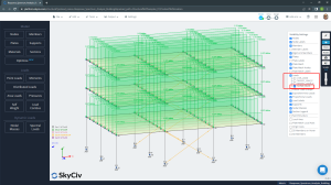
Figure No. 13. Equivalent line load applied to secondary beams: Superimposed dead load.

Figure No.14. Equivalent line load applied to secondary beams: Live load.
Response spectrum analysis, RSA – applying loads
To calculate lateral seismic forces dynamically using this method (RSA) you can follow the next steps:
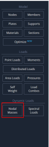
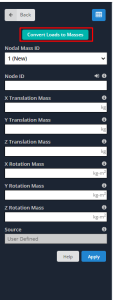
- Nodal masses. You can define masses by putting them directly in structure nodes or through the conversion of applied loads.
Most building codes have considered only as a source of mass the self-weight and superimposed dead loads to calculate seismic inertial forces. In some uncommon cases, a fraction of live loads are also accounted for.
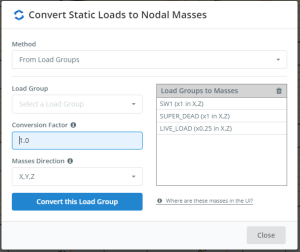
Figure no. 15. Mass sources including self-weight, superimposed dead and 25% of live load.
- Spectral Loads. In this section, you will define all data required to build the spectrum plot.
There are two manners to create the plot for RSA. SkyCiv S3D offers you using a user input or with a default template that includes the ASCE-07, NBCC 2020 and Eurocode 8 codes.
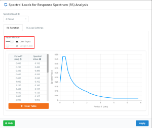
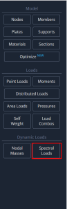
Figure no.16. Spectral loads option in SkyCiv S3D.
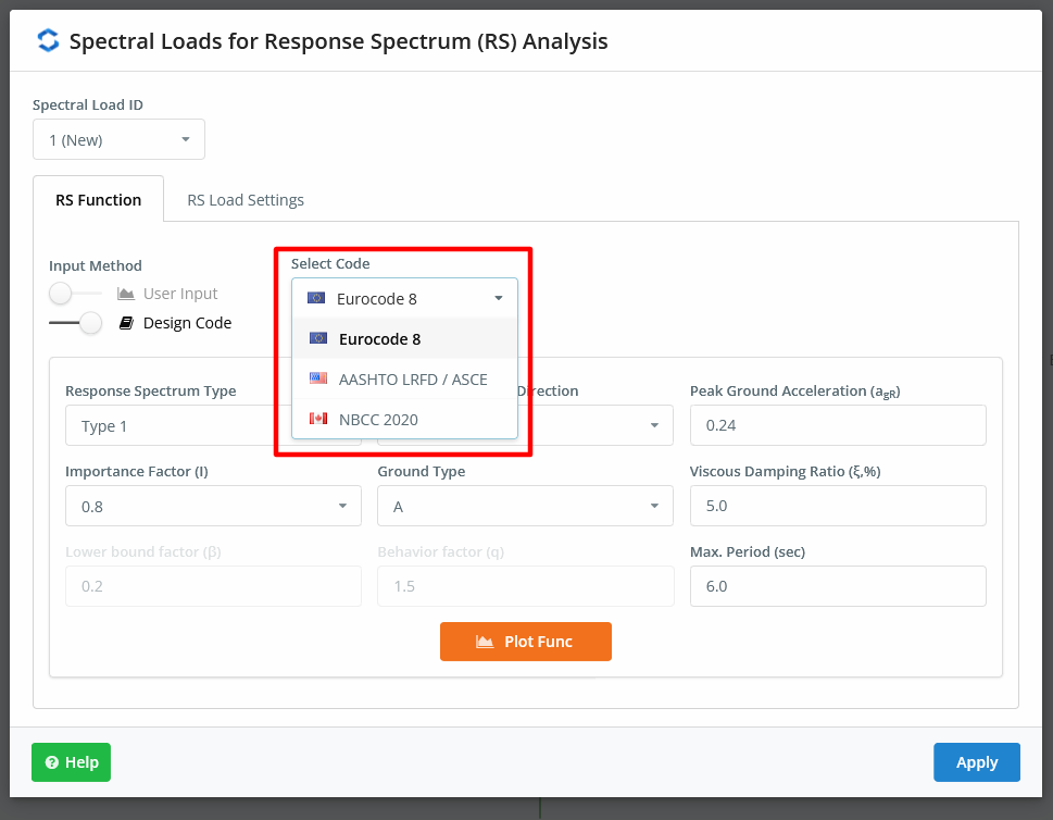
Figure no.17. Default construction codes to spectral loads.
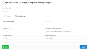
Figure no. 18. Settings related to modal response
Due to the RSA being a dynamic analysis method based on the modal response, there has to be a previously defined procedure to combine these different modal responses. Most adequate methods are indicated below and is fully recommended to use the CQC method: “Complete Quadratic Combinations”. For more information about modal combination methods, check this article.
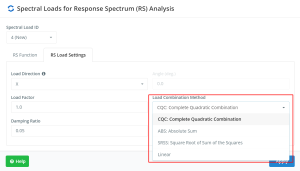
Figure no. 19. Rules to combine modal results
- Reduced Design Spectrum. It is almost impossible to design any building to resist elastic seismic forces due to the high construction costs this would imply. For this reason, a majority of building codes allow the use of lower seismic forces than those mentioned before. To do that, every construction system has properties such as ductility and strength which permit dissipate seismic energy and accommodate horizontal displacement. Therefore, you can reduce the lateral design forces through the Reduced Design Spectrum.
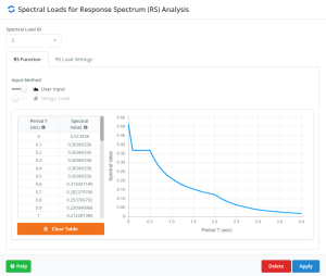
Figure no.20. Reduced Design Spectrum Plot.
The example we’ve been working with has two different lateral resistance systems: braced and moment frames. Both systems respond inelastically in different modes so that, ductility and strength factors will modify the Reduced Design Spectrum to be used in each main direction.
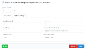
Figure no.21. Reduced Design Spectrum Analysis Settings in “X” direction.
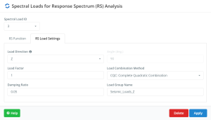
Figure no.22.
Reduced Design Spectrum Analysis Settings in “X” direction.
Reviewing natural vibration frequencies
Once all dynamic properties have been defined you may run a Response Spectrum Analysis. Go to “Solve” and then select “Response Spectrum” to obtain the final results. We can review the natural vibration periods or frequencies for all modes considered in the analysis.
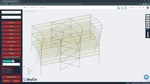
Figure no.23. First mode of natural vibration result. Period, T1 = 1.412 seconds
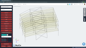
Figure no.24. Second mode of natural vibration. Period, T2 = 1.021 seconds

Figure no.25. Third mode of natural vibration. Period, T3 = 1.021 seconds.
Finally, you can access tables with the RSA results. The next images show the frequencies and participation masses for all modes of vibration in the analysis.
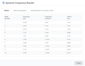
Table no.26. Dynamic Frequency Results – 10 modes of vibration.
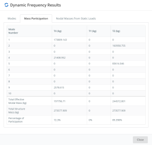
Table no.27. Dynamic Frequency Results – Mass participation.