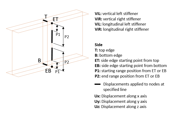
Stiffeners
The displacements can be applied to the nodes arranged on the edges of stiffeners. Here in the table row, you select the stiffener and its edge and then define the directed displacement with its value. The displacement will be distributed equally among the nodes of the selected edge. The nodal displacement with the values can be previewed by clicking on the Preview button.
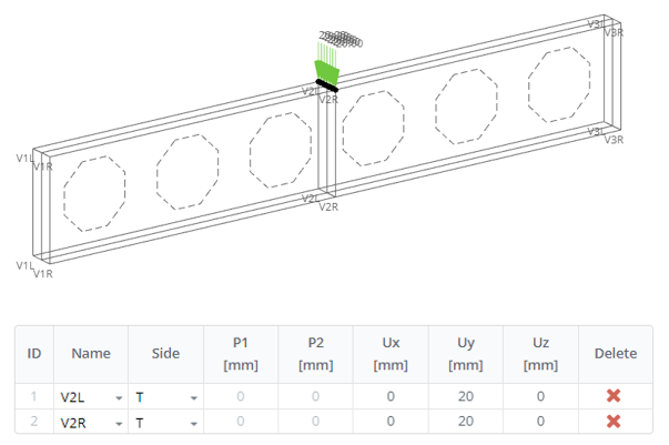
Example of input
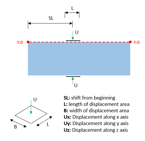
Area
The displacement is applied to the area on a beam flange. Here you select the flange, position of the center of a load area from the left side of a beam (SL), length (L), and width (B) of the area, and directed displacement with its value. The displacement will be distributed among the nodes inside the area. The nodal displacement with the values can be previewed by clicking on the Preview button.
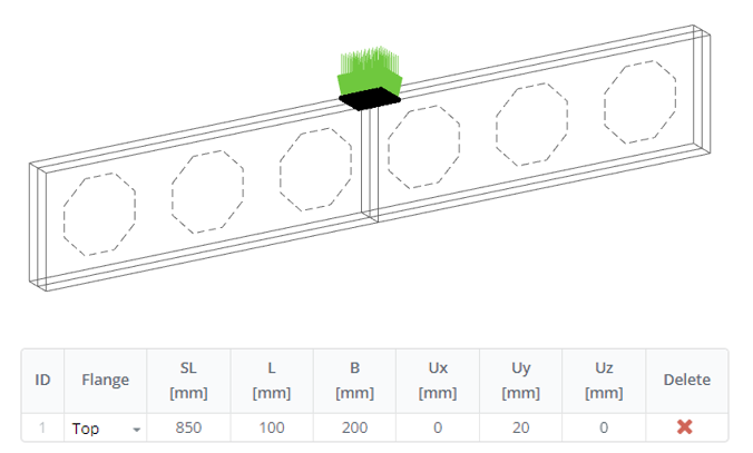
Example of input
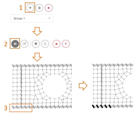
Nodes (Custom)
Start by creating a new group using the ‘+’ button. Then, select the nodes and define displacements for them. If you need different displacements, create another group for nodes. Selection or deselection can be achieved using either the frame or polygon tools
Load Amplitude
The applied displacement is incorporated into the load-time amplitude group. For more details, refer to Analysis > Load Amplitude