General Settings

Units Settings
These settings can be accessed by clicking the ‘Settings’ button on the top bar when using SkyCiv Structural 3D. The three tabs at the top of the settings box will allow you to toggle between the various settings.
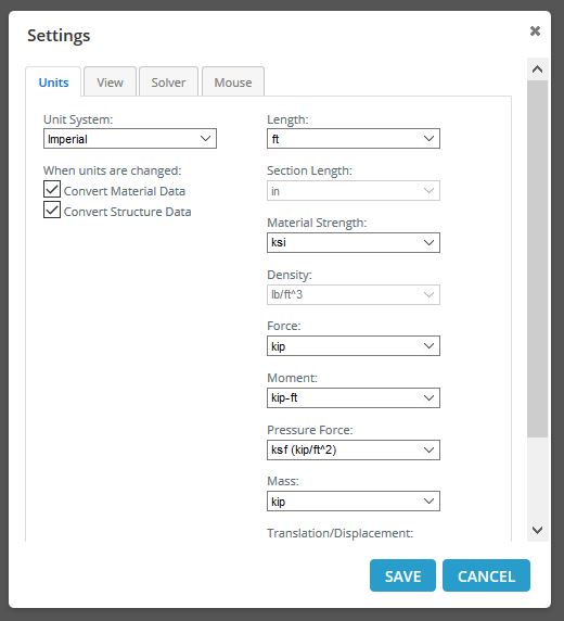
- Unit System: Choose between Metric (kN, m, MPa) and Imperial (kip, ft, ksi) unit systems for force, length, and pressure.
- Convert Material Data: If this is ticked on, then whenever the unit system changes the material data values will be converted to the new unit system.
- Convert Structure Data: If this is ticked on, then whenever the unit system changes the data values of the structure (except materials) will be converted to the new unit system.
View Settings
View settings controls how your wireframe model is viewed.
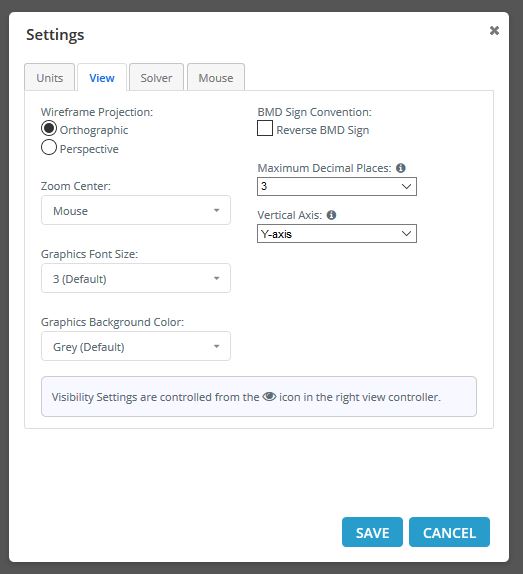
- Wireframe Projection: Select one of these options to change the current projection mode view of your wireframe model. The Perspective view provides a more realistic view, but it is harder to visualize 3D coordinates and lengths compared to orthographic projection.
- Reverse BMD Sign: This setting reverses the sign convention of the bending moment diagrams in post-processing.
- Zoom Center: Changes which location the model space will zoom in/out on. With Mouse selected, it will zoom wherever your cursor is.
- Maximum Decimal Places: The rounding of all results on diagrams to a specific number of decimal places. The default is 3 decimal places.
- Vertical Axis: Choose which axis you prefer as the vertical axis (Y or Z).
- Graphics Font Size: Change the size of graphic labels in the model space. These include node labels, member labels, load labels, etc.
- Graphics Background Color: Change the color of the background in the model space.
Note that the visibility settings of the model can be changed within Visibility Settings.
Solve Settings
These settings typically relate to how the solver will calculate the solution for the analysis of the model.
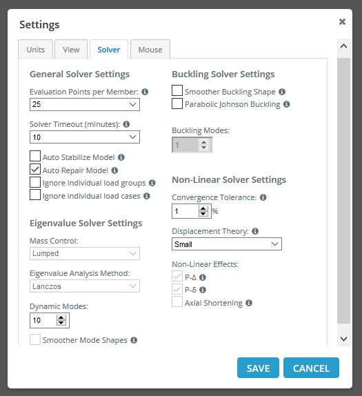
On the left you will find General Solver Settings:
- Evaluation Points per Member: The number of evaluation points used for each member. Increase this for higher accuracy results but slower solve time and responsiveness. SkyCiv recommends using 9 (the default) unless the structure is large, in which case using 5 will be make the software behave faster.
- Solver Timeout: The maximum time span allowed for the solver to run before timing out (measured in minutes). Change this based on the size of your structure. 1.5 minutes is the default and should be more than enough time for most structures under 300 members.
- Auto Stabilize Model: The solver will attempt to automatically stabilize your model if it has trouble converging due to instabilities. This is especially useful with non-linear analyses that fail to converge.
- Auto Repair Model: If ticked on, then the Repair Model function will automatically run before solving to check if the model has issues that may need repairing. It will only check for missing sections and nodes that need merging.
- Ignore individual load groups: Disregard individual load groups from your model’s envelope results
- Ignore individual load cases: Disregard individual load cases from your model’s envelope results
Below this section you will find the Eigenvalue Solver Settings:
- Mass Control: Decide what idealized mass system to attribute to your structure during the seismic analysis
- Eigenvalue Analysis Method: Choose which algorithm you would like to solve for the eigenvalues
- Dynamic Modes: Change the number of dynamic modes that you wish your model to exhibit during dynamic frequency.
On the right you will find the advanced Buckling and Non-Linear Solver Settings:
- Parabolic Johnson Buckling: Toggle the use of the parabolic or J.B. Johnson formula when engaging with buckling analysis. This is a more conservative approach to buckling analysis of intermediate-length columns.
- Convergence Tolerance: The Non-Linear Solver will continue to solve until this tolerance is met. A smaller number takes longer to solve as a more accurate solution is obtained during the convergence of residuals and displacements.
- Displacement Theory (Small or Finite): This controls the displacement theory for the Non-Linear Solver. Finite displacement theory is similar to Large displacement theory in that it takes into account the full movement of the structure during the analysis and is suitable when the displacement is large. The default is “Small” as usually displacement is not so significant – in this case, the results between Small and Finite theory should be similar.
- Non-Linear Effects: When the displacement theory is changed, certain non-linear effects are taken into consideration as indicated by these checkboxes. At the moment P-Delta (P-Δ), P-delta(P-δ), and Axial Shortening effects cannot be toggled by the user and are automatically chosen depending on the Non-Linear theory chosen.
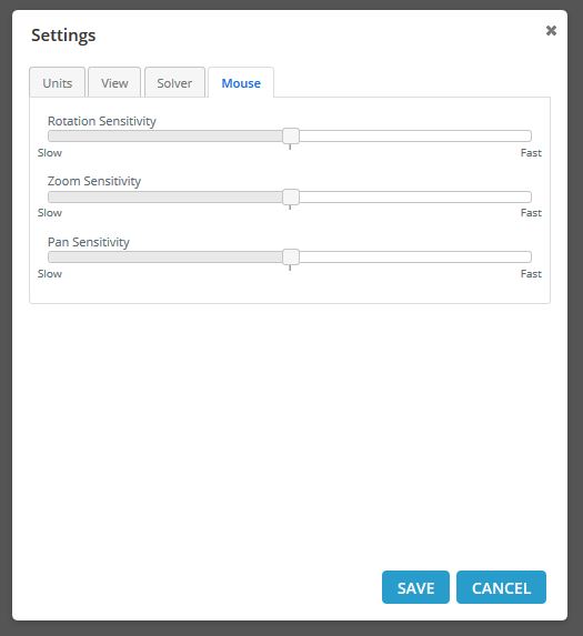
Mouse Settings
These settings adjust the sensitivity of your mouse actions in the model space.
Visibility Settings
Visibility Settings allows you to control what is being shown on your structure. With structures of increasing complexity (e.g. with multiple members, plates, loads), the information being presented on the structure becomes more and more cluttered. To selectively filter the information being presented, enter the Visibility Settings by clicking the ‘Eye’ icon on the right menu:
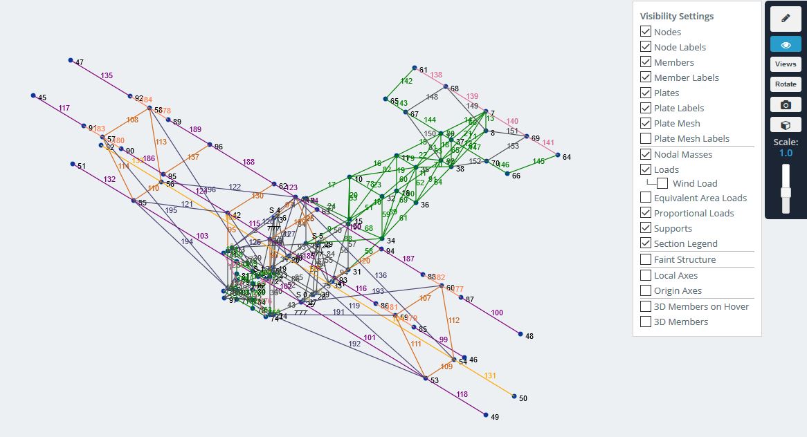
- Nodes: toggles the display of Nodes themselves.
- Node Labels: toggles the display of Node IDs.
- Members: toggles the display of Members themselves.
- Member Labels: toggles the display of Member IDs.
- Plates: toggles the display of Plates themselves.
- Plate Labels: toggles the display of Plate IDs.
- Plate Mesh: toggles the display of Plate Meshes themselves.
- Plate Mesh Labels: toggles the display of Mesh IDs.
- Nodal Masses: toggles the display of any applied nodal masses.
- Loads: toggles the display of Loads which is further broken down into your Load Groups.
- Equivalent Area Loads: toggles the display of the equivalent load distribution on members of applied area loads
- Proportional Loads: toggles the display of proportional loads based on their relative values to each other
- Supports: toggles the display of your Supports.
- Section Legend: toggles the display of your Section Legend.
- Faint Structure: slightly fades the members of the structure.
- Local Axes: toggles the display of a Members Local axis.
- Origin Axes: toggles the display of the zero coordinate Global Axis.
- 3D Members on Hover: when selected, hover over your wireframe members to show the faint 3D rendered version.
- 3D Members: another way to toggle on or off the 3D rendered version of your model.