What is an eccentric load?
An eccentric load is any load that is not applied to the centroid of the member. In finite element analysis, point loads, distributed loads, and other forces are generally applied to the centroid of the section (i.e. the geometric center of the section). However, in certain scenarios you may wish to apply a force off center – for instance, applying a load to the flange of an I-beam, rather than the web. Assuming this is a lateral load, this will create a torsional force and an overall different loading behavior in the member.
How to apply eccentric loads to a model
Here we’ll take you through an example of how you can use Rigid Links to apply such an eccentric load. By using Rigid Links, we can transfer the load from the centroid of the member to a different location. Rigid Links are extremely useful for this sort of work, as it automatically calculates the resultant moment and other forces from one location to another.
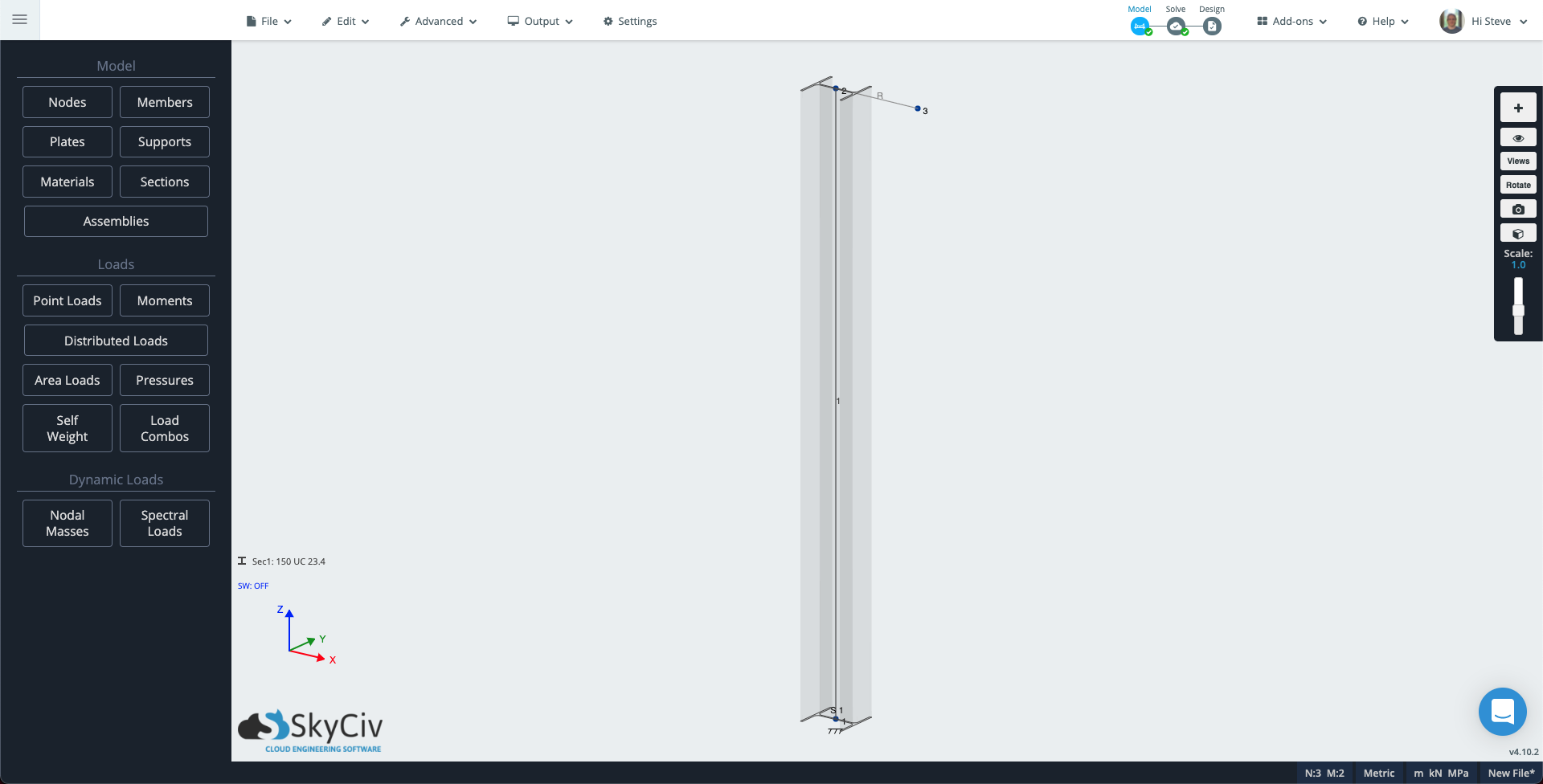
Head over to S3D and create a new model. Next, select the pen tool in the right panel or by tapping V. Click once to place the first node at the origin, then draw upward about 2m (6.5ft) to create a column.
Down in the corner by the coordinate system, click Sec1: Not Defined, then in the left panel, click Builder to open section builder. Choose a column section, for this tech-note I have selected an Australian 150UC23.4, this is about a 6×6 I section for our imperial friends. In the left panel, click supports and add fixed support at Node 1.
Now we will add another member so we can create an eccentric load that induces torsion and another that creates a buckling effect on our column.
To see the orientation of your column, click the visibility icon on the right panel and select 3D Members. Use the pen tool to draw a 300mm (1ft) member in the X direction from the top of the column. If “3D member” is switched on, you will see this member uses the column section. Click the new member, then in the left panel, change the type attribute to Rigid and click Apply.
Your model should look similar to the below:
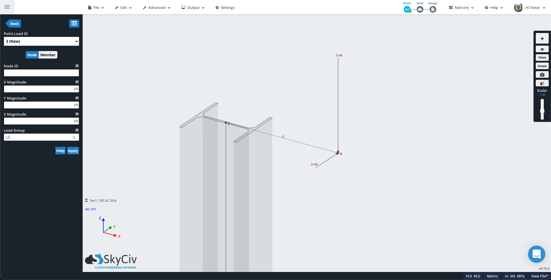
Click Point Loads in the left panel. Fill out the attributes with the following values:
- Node ID: 3
- Z Magnitude: -5 (If your model uses the Y-axis as vertical, add this value to Y Magnitude instead).
- Load Group: Buckling Load
Click apply and the point load will be added to the model. The Point Load ID will increment to 2 (New) so add another load to create torsion in the column:
- Node ID: 3
- Y Magnitude: 2 (If your model uses the Y-axis as vertical, add this value to Z Magnitude instead).
- Load Group: Torsion Load
Node 3 of your model should now look something like the following.
Run the solver, then open render mode – the cube icon in the right panel. Change the drop-down in the left panel to Buckling load, the deflection scale to Auto, and the Member Results dropdown to Displacement Sum. You can now see how the first eccentric load is causing a buckling effect.
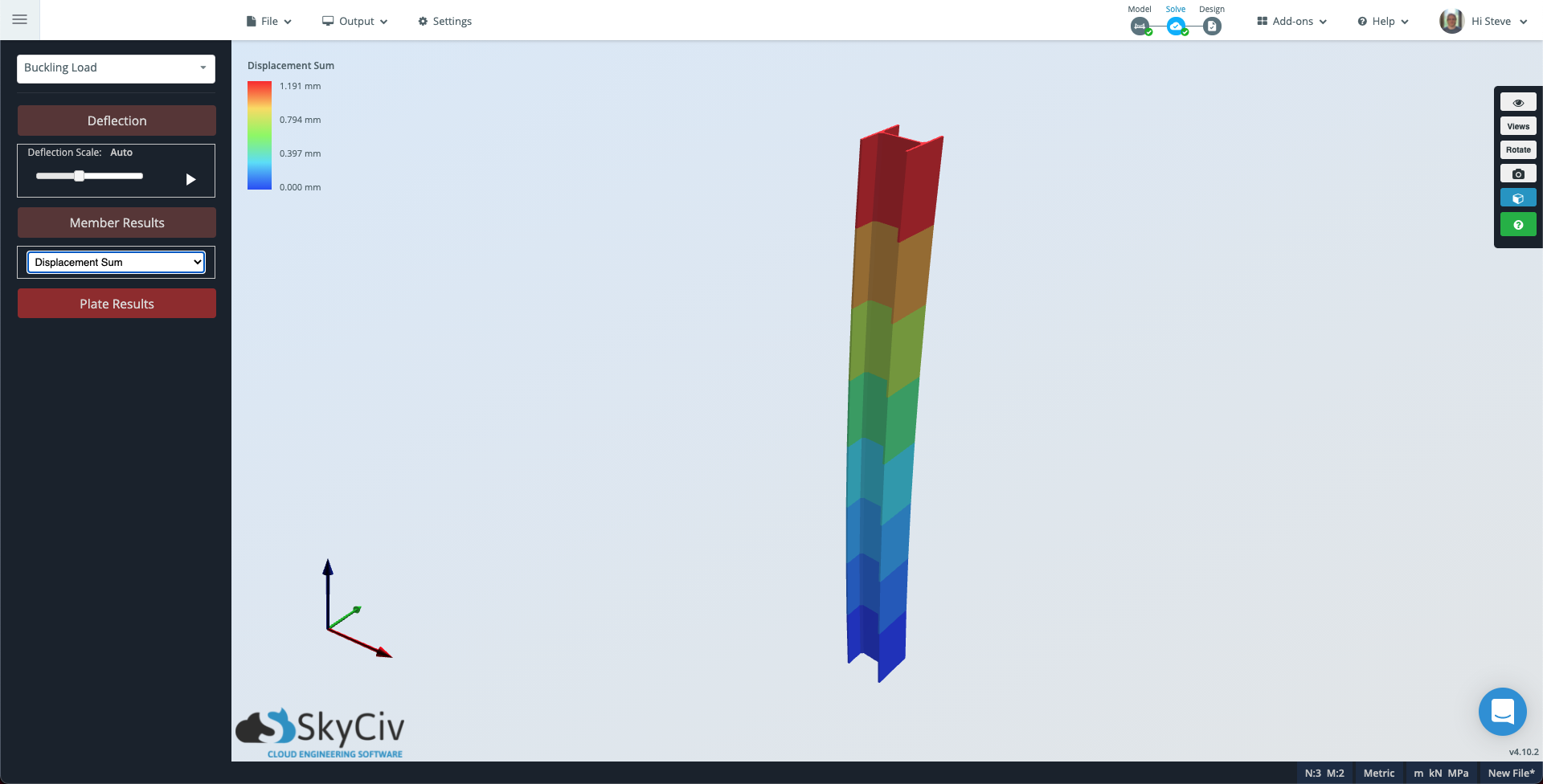
Note that if you would like to see a finer subdivision of the member you can go to Settings → Solver, change the Evaluation Points per Member to a suitable number and run solve again.
Now change the dropdown from Buckling Load to Torsion Load and the Member Results to Torsion Stress. In this case, the member will appear grey as the torsion load is consistent throughout the member.
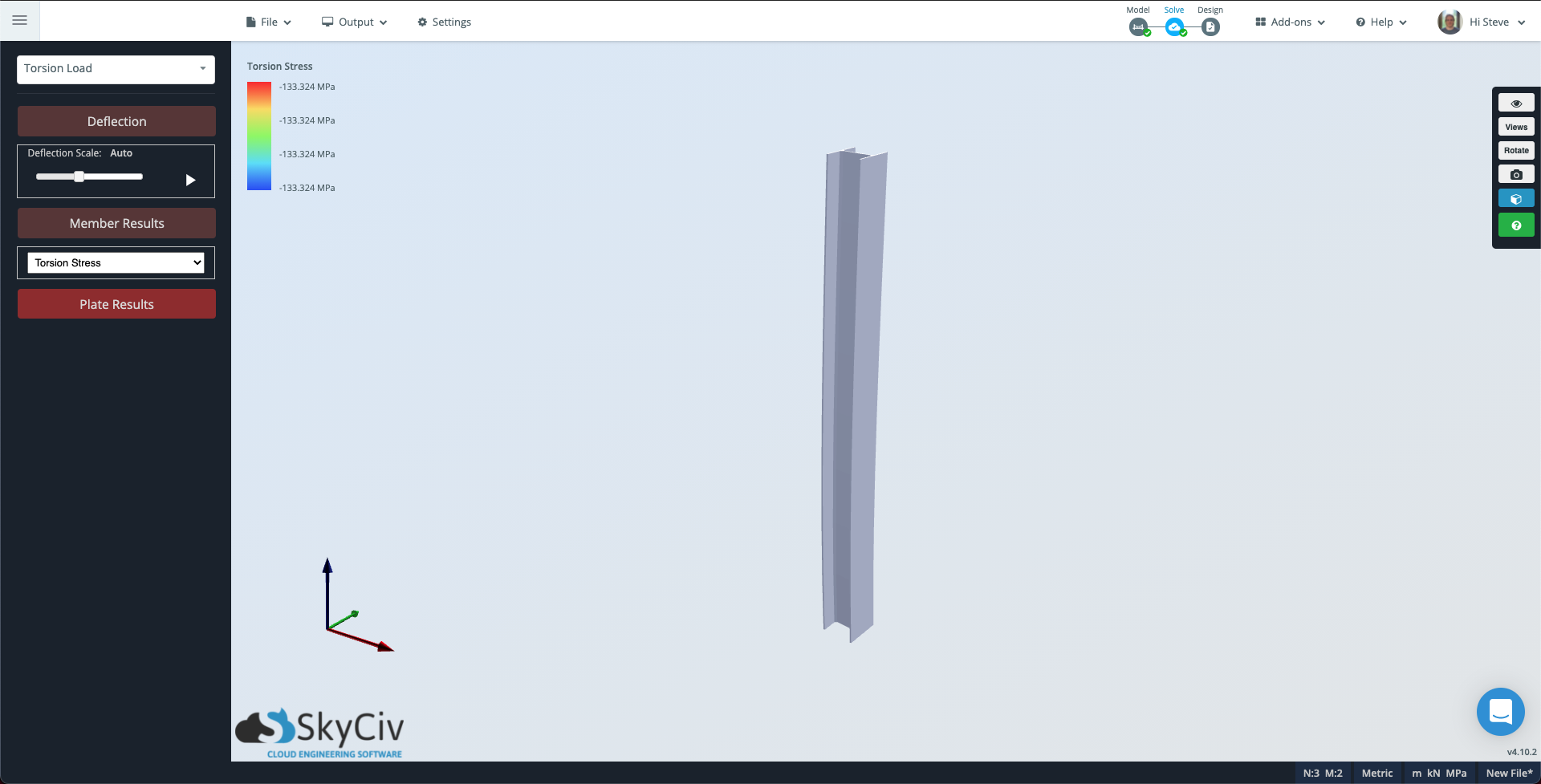
Notice that the contour scale in the top left still shows the magnitude of torsion that the column is experiencing.