Model Details and Parameters
Determine the displacements of a hemispherical shell subjected to concentrated tensile and compressive loads in two orthogonal radial directions.
Only a quarter model may be analyzed due to symmetry.
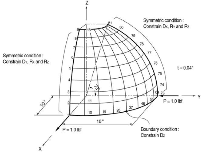
Structural geometry
- Analysis Type
3-D static analysis - Dimension
Radius: 10.0 in - Plate Type
Mindlin Plane Stress - Material
Structural Steel
Young’s Modulus: 68250 ksi
Poisson’s Ratio: 0.3 - Element Property
Plate Thickness: 0.04 in - Boundary Supports
Nodes 1 – 9: Constrain Dy, Rx and Rz. (Symmetric about X-Z plane)
Nodes 73 – 81: Constrain Dx, Ry and Rz. (Symmetric about Y-Z plane)
Node 37: Constrain Dz. (To prevent the rigid body motion in the Z direction) - Loads
A concentrated load, 1.0 lbf is applied to the node 1 in the X direction
A concentrated load, 1.0 lbf is applied to the node 73 in the -Y direction
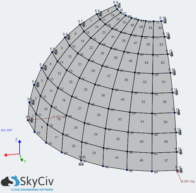
Analysis model
Results
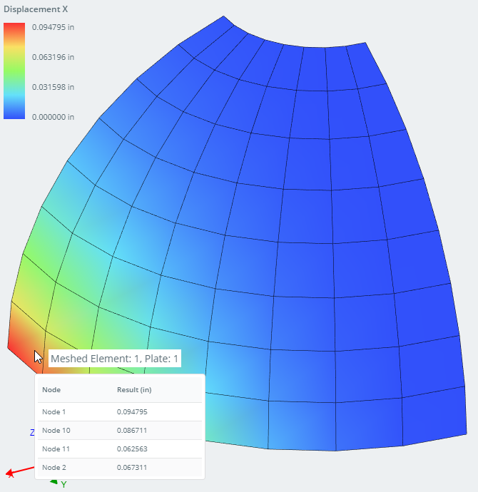
X-displacements of the structure (Node 1)
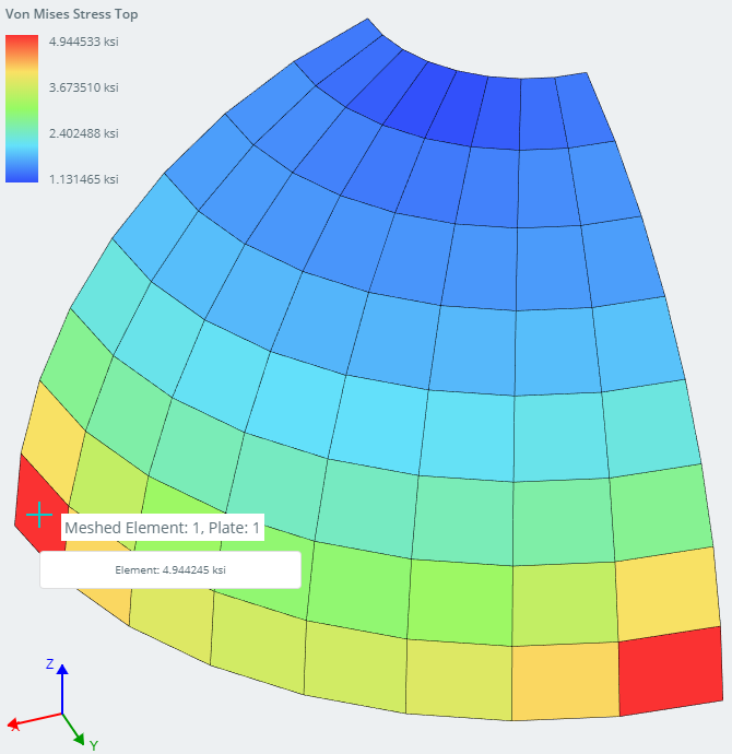
Von Mises Stress of the structure (Element 2)
Comparison of Results
| Result | Location | SkyCiv | Theoretical | Difference 1 | Third-Party 2 | Difference 2 |
| Max Displacement X (in) | Node 1 | 0.094795 | 0.094000 | 0.85% | 0.094789 | 0.01% |
| Max Von Mises Stress – Element (ksi) | Element 1 Top | 4.944245 | 4.989211 | 0.90% |
Reference
MacNeal, R. H. and Harder, R. C., “Proposed Standard Set of Problems to Test Finite Element Accuracy”, Finite Elements in Analysis and Design 1, 1985, pp. 3-20, NorthHolland.
Extra Considerations
- This verification model was created and checked on 26 April 2020. Since this date, the plate solver and S3D software may have been further improved to achieved greater accuracy.
- Plates are not exact elements like beam and frame elements and therefore the mesh plays a huge role in the results. Always try to use a structured mesh when it is possible to do so.
- Results between software will never be exactly the same since different elements are used and the nature of plates are approximate