A fully worked example of Ground-mounted Solar Panel Wind Load and Snow Pressure Calculation using ASCE 7-16
With the recent trends in the use of renewable energies to curb the effects of climate change, one of the fasting growing industries as a solution to this problem is the use of solar energy. Moreover, solar panels are also getting popular among household consumers as an alternative source of energy as electricity has skyrocketed for the past few years. In effect, solar panel installations on roofs of houses and construction of solar farms which use ground-mounted solar panels increase in number. The need for calculating wind load on solar panels as well as the snow pressures is critical for these to achieve durability. In this article, we will be discussing how to calculate the snow and wind loads on ground-mounted solar panels using ASCE 7-16.
SkyCiv automates the wind speed calculations with a few parameters. Try our Solar Panel Wind Load Calculator
Structure Data
In this example, we will use the following data:
Table 1. Building data needed for our wind and snow load calculation.
| Location | 395 Rocky Point Rd, Cordova, Memphis, Tennessee |
| Occupancy | Miscellaneous – Solar Panel |
| Terrain | Flat farmland |
| Panel Width | 16.25 ft |
| Panel Length | 13.33 ft |
| Mounting Height | 8.33 ft |
| Tilt Angle | 30° |
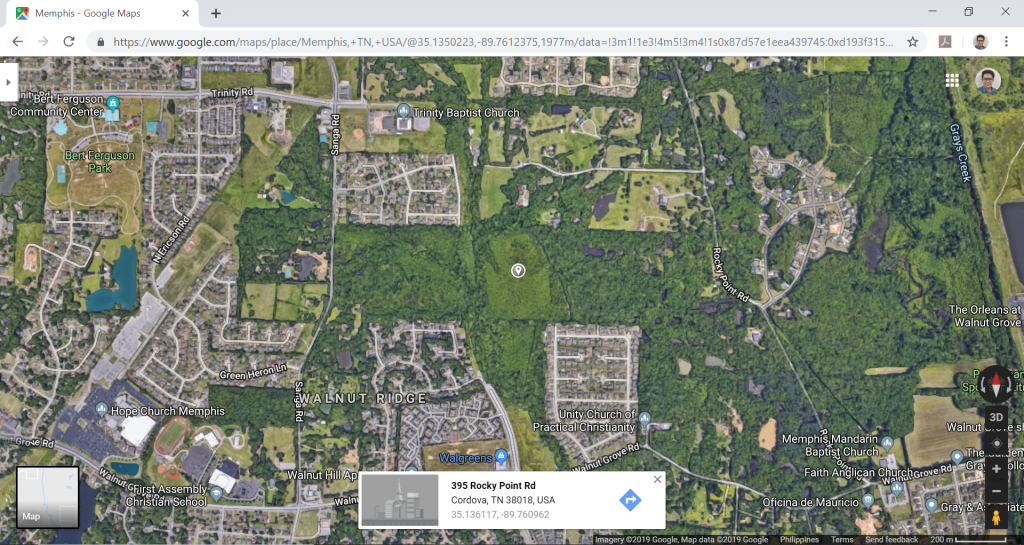
Figure 1. Site location (from Google Maps).
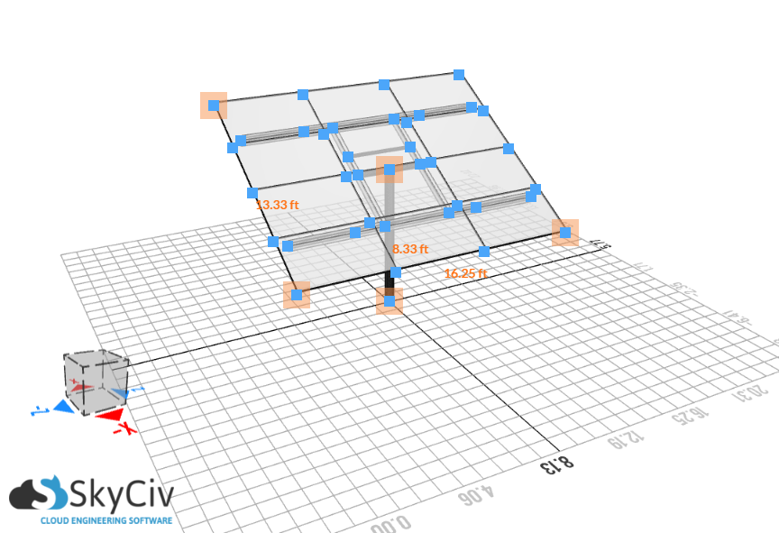
Figure 2. The solar panel dimensions.
Wind Loading
In calculating wind load on solar panels, we will be using the ASCE 7-16 Chapter 27 – Wind Load – Directional Procedure. We will consider the ground-mounted solar panel as an open building with monoslope roof when the tilt angle is less than or equal to 45° and as a solid sign for tilt angle greater than 45°.
The formula in determining the design wind pressures are as follows:
For tilt angle ≤ 45° (considered as open building with monoslope roof):
\(p = {q}_{h}G{C}_{N}\) (1)
For tilt angle > 45° (considered as solid sign):
\(p = {q}_{h}G{C}_{f}\) (2)
Where:
\(G\) = gust effect factor
\({C}_{N}\) = net force coefficient for open monoslope roof
\({C}_{f}\) = net force coefficient for solid signs
\({q}_{h}\) = velocity pressure at reference height, \(h\), in psf, given by the formula:
\({q}_{h} = 0.00256{K}_{z}{K}_{zt}{K}_{d}{K}_{e}V^2\) (3)
\({K}_{z}\) = velocity pressure coefficient
\({K}_{zt}\)= topographic factor
\({K}_{d}\) = wind directionality factor
\({K}_{e}\) = ground elevation factor
\(V \) = basic wind speed in mph
Take note that for tilt angle > 45°, we the dimensions to be used are the vertical projection of the solar panel and then use the formula for net force coeffients for solid signs. We will dive deep into the details of each parameter below.
Risk Category
The first step is to determine the Risk Category of the solar panel based on the use or occupancy. From Table 1.5-1 of ASCE 7-16, we can classify the ground-mounted solar panel in this example to Risk Category I.
Basic Wind Speed, \(V\)
The ASCE 7-16 provides a wind map where the corresponding basic wind speed of a location can be obtained from Figures 26.5-1A to 1C. From Figure 26.5-1A, Cordova, Memphis, Tennessee is somehow near where the red dot on Figure 3 below, and from there, the basic wind speed, \(V\), is 100 mph. Take note the basic wind speed value is interpolated from the nearest wind contours.
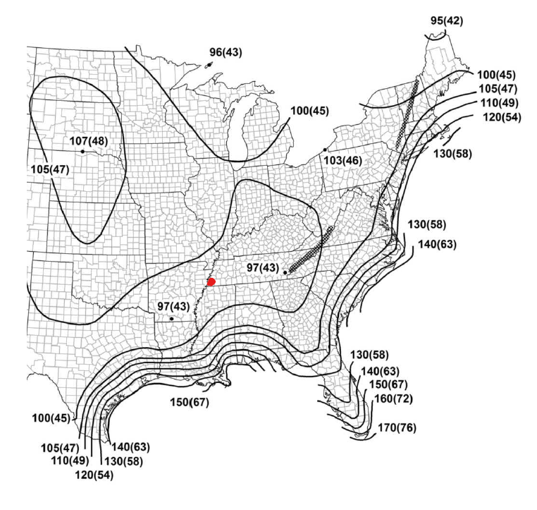
Figure 3. Basic wind speed map from Figure 26.5-1A of ASCE 7-16 (Risk Category I) with red dot to indicate the location of our solar panel.
SkyCiv automates the wind speed calculations with a few parameters. Try our Solar Panel Wind Load Calculator
Exposure Category
Depending on the wind direction being analyzed, the exposure category of the solar panel shall be determined from the upwind 45° sector based on Section 26.7 of ASCE 7-16. Moreover, Section C26.7 provides aerial photographs showing examples of Exposures B, C, and D in Figures C26.7-5 to C26.7-7.
In this example, we will only use wind coming from the South direction. Hence, based on the aerial photograph examples, we can classify the upwind terrain to Exposure C based on Figure C26.7-6(b) or “Open Terrain with Scattered Obstructions Having Heights Generally Less than 30 ft (9.1 m)” as shown in Figure 4 below. We will use Exposure Category in calculating Velocity Pressure coefficient \({K}_{z}\)span> and/or Topographic factor \({K}_{zt}\) if needed.
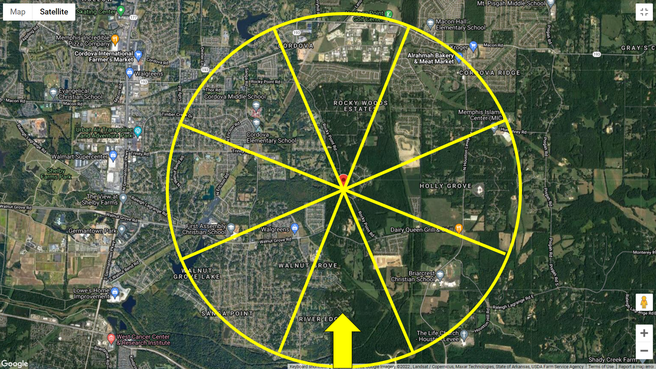
Figure 4. Aerial photograph of terrain with wind coming from the South.
Wind Directionality Factor, \( {K}_{d} \)
The wind directionality factor, \({K}_{d} \), for the solar panel is equal to 0.85 since the solar panel can be considered as MWFRS (open monoslope) when the tilt angle is less than or equal to 45° and as a solid sign for tilt angle greater than 45° based on Table 26.6-1 of ASCE 7-16.
Ground Elevation Factor, \( {K}_{e} \)
The ground elevation factor, \({K}_{e} \), can be calculated using Table 26.9-1 of ASCE 7-16. For this example, since the site elevation is equal to 350.48 ft, \({K}_{e} \) can be calculated using the formula:
\( {K}_{e} = {e}^{-0.0000362{z}_{g}} \) (4)
\( {K}_{e} = {e}^{-0.0000362(350.48)} = 0.987\)
\( {K}_{e} = 0.987 \)
Using Equation (4), \({K}_{e} \) is equal to 0.987.
Topographic Factor, \( {K}_{zt} \)
The parameters to calculate the topographic factor, \({K}_{zt}\), are detailed in Figure 26.8-1 of ASCE 7-16. To determine if further calculations of the topographic factor are required, we need to check it using Section 26.8.1. If the site does not meet all of the conditions listed, then the topographic factor can be taken as 1.0. From the ground elevation generated from Google elevations, we can assume that the terrain is Flat, therefore, \({K}_{zt}\) can be assumed to be 1.0 for wind coming from South.
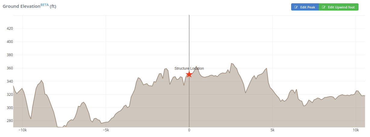
Figure 5. Elevation profile of site on S-N wind direction.
Velocity Pressure Coefficient, \({K}_{z}\)
The velocity pressure coefficient, \({K}_{z}\), can be calculated using Table 26.10-1 of ASCE 7-16. This parameter depends on the height above ground level of the point where the wind pressure is considered, and the exposure category. Moreover, the values shown in the table is based on the following formula:
For 15ft < \({z}\) < \({z}_{g}\): \({K}_{z} = 2.01(z/{z}_{g})^{2/α}\) (5)
For \({z}\) < 15ft: \({K}_{z} = 2.01(15/{z}_{g})^{2/α}\) (6)
Where:
Table 3. Values of α and \({z}_{g}\) from table 26.11-1 of ASCE 7-16.
| Exposure | α | \({z}_{g}\) (ft) |
|---|---|---|
| B | 7 | 1200 |
| C | 9.5 | 900 |
| D | 11.5 | 700 |
For this example, we will consider the solar mounting height elevation.
\({K}_{z} = 2.01((15)/(900))^{2/(9.5)} = 0.85 \)
\({K}_{z} = 0.85 \)
Velocity Pressure
From Equation (3), we can solve for the velocity pressure, \( {q}_{h}\) in psf, at mounting height equal to 8.33 ft.
\({q}_{h} = 0.00256{K}_{z}{K}_{zt}{K}_{d}{K}_{e}V^2\)
\({q}_{h} = 0.00256(0.85)(1.0)(0.85)(0.987)(100)^2 = 18.256 psf\)
\({q}_{h} = 18.256 psf\)
To calculate for the design wind pressure, we will be using Equation (1). Details of these parameters are shown below.
Gust Effect Factor, \(G\)
In determining the gust effect factor, \(G\), we first need to calculate the fundamental natural frequency of the structure \( {n}_{1} \). If \( {n}_{1} \) is less than 1 Hz, it will be classified as flexible structure, hence we will need to calculate for \(G\) using Section 26.11.5. In this example, for simplified approach, we will assume that our solar panel is rigid, where \(G\) is equal to 0.85 based on Section 26.11.1 of ASCE 7-16. It should be noted that due diligence in checking the fundamental natural frequency of the structure is needed in determining the gust effect factor especially for flexible structures since it will magnify this parameter.
Net Pressure Coefficient, \({C}_{N}\), Tilt Angle ≤ 45°
To determine the net pressure coefficients, \( {C}_{N} \), we will assume the solar panel as open building with monoslope roof. We can get these values from Figure 27.3-4 of ASCE 7-16 with the assumption of “Clear Wind Flow.” Take note that these values are only applicable to solar panels with tilt angle less than or equal to 45°
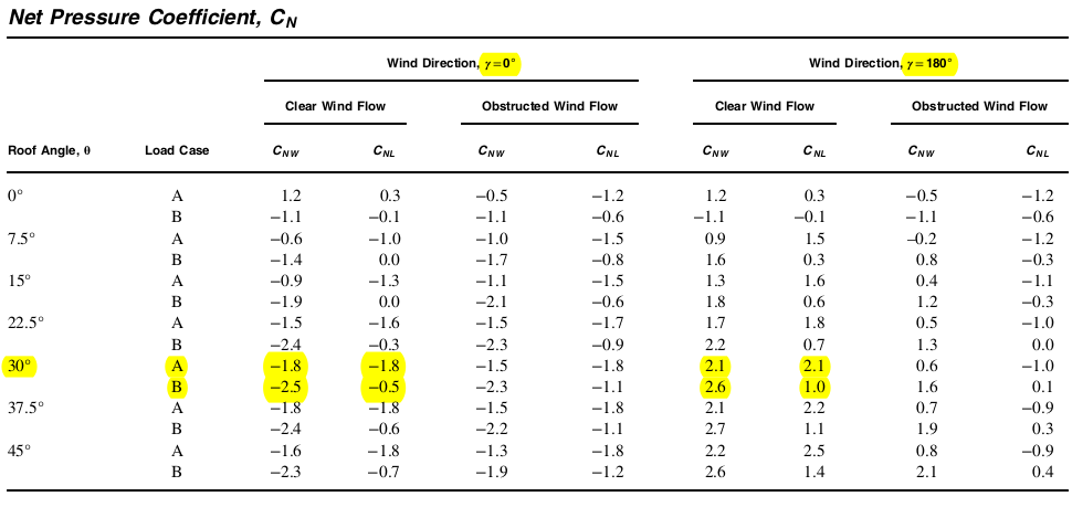
Figure 6. Net pressure coefficient, \( {C}_{N} \), values from Figure 27.3-4 of ASCE 7-16 for open building with monoslope roof.
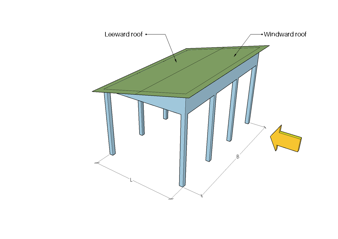
Figure 7. Windward and leeward zones for direction angle equal to 0° .
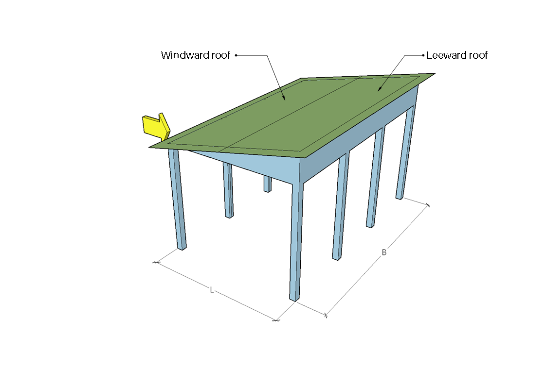
Figure 8. Windward and leeward zones for direction angle equal to 180°.
Since the tilt angle of the solar panel is equal to 30°, the corresponding net pressure coefficients, \( {C}_{N} \), to be used are as follows:
Table 4. Values of \( {C}_{N} \) to be used based on Figure 27.3-4 of ASCE 7-16.
| Load Case | Direction = 0° | Direction = 180° | ||
|---|---|---|---|---|
| \( {C}_{N,windward} \) | \( {C}_{N,leeward} \) | \( {C}_{N,windward} \) | \( {C}_{N,leeward} \) | |
| A | -1.8 | -1.8 | 2.1 | 2.1 |
| B | -2.5 | -0.5 | 2.6 | 1.0 |
Note that a negative value means that the wind pressure is acting away from the surface and positive value denotes wind pressure acting towards the surface. From Table 4, it can inferred that we will consider four (4) load cases for wind load on our solar panel.
Design Wind Pressures – Tilt Angle ≤ 45°
In calculating wind load on solar panels with tilt angle > 45°, we will be using Equation (1), hence, the wind loads on ground-mounted solar panels:
\({q}_{h} = 18.256 psf\)
\( G = 0.85\)
Table 5. The calculated wind loads on ground-mounted solar panels to be applied to the structure.
| Load Case | Direction = 0° | Direction = 180° | ||
|---|---|---|---|---|
| Windward, psf |
Leeward, psf | Windward, psf | Leeward, psf | |
| A | -27.932 | -27.932 | 32.587 | 32.587 |
| B | -38.794 | -7.759 | 40.346 | 15.518 |
Therefore, the wind loads on ground-mounted solar panels when applied are as follows:

Figure 9. Design wind pressures for direction angle 0° – Load Case A.
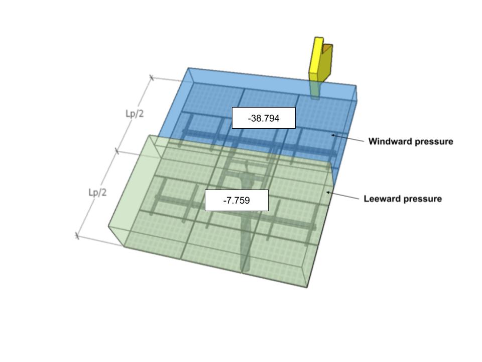
Figure 10. Design wind pressures for direction angle 0° – Load Case B.
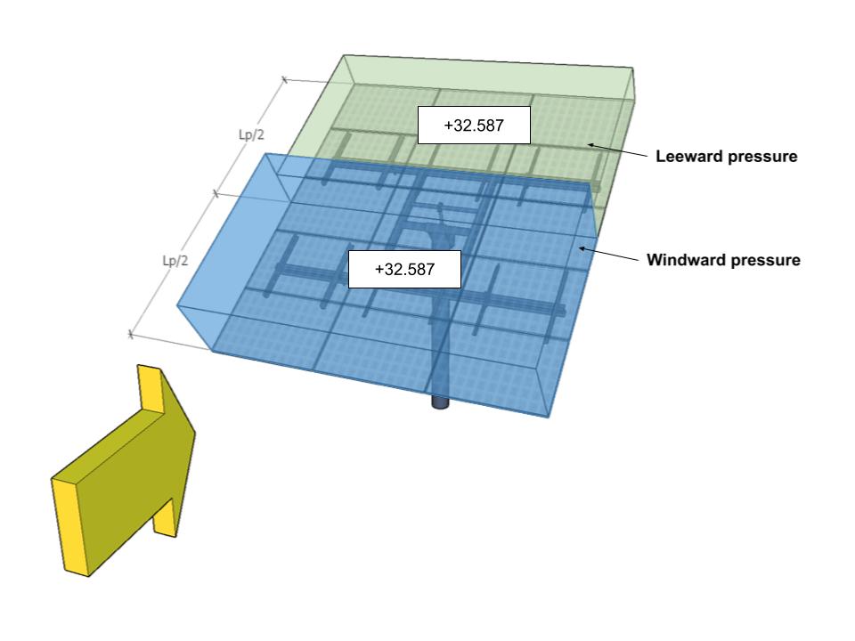
Figure 11. Design wind pressures for direction angle 180° – Load Case A.

Figure 12. Design wind pressures for direction angle 180° – Load Case B.
Net Force Coefficient, \({C}_{f}\), – Tilt Angle > 45°
Let’s say that our solar panel tilt angle was changed to 60°. We need to use the vertical projection of the solar panel and consider it as a solid sign with the velocity pressure calculated up to the top of this projection.
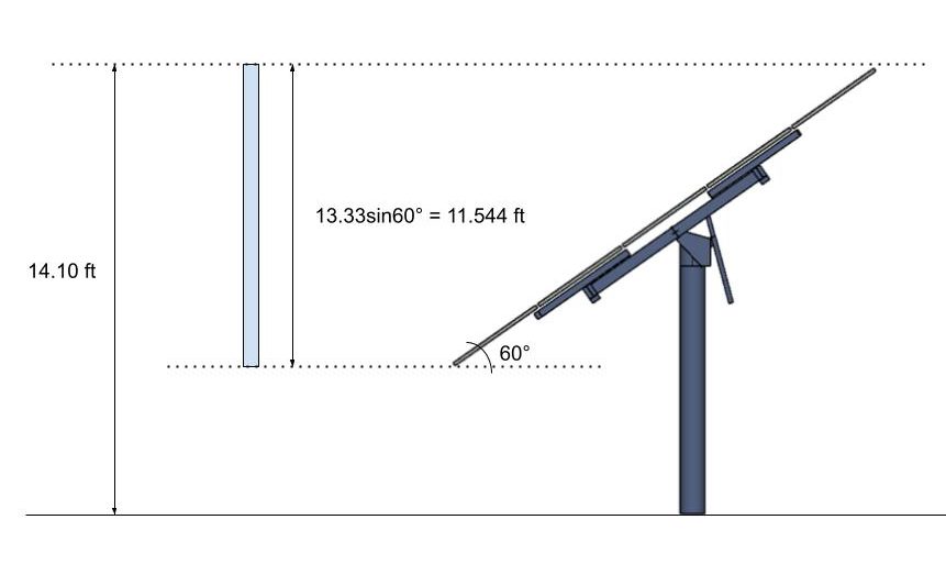
Figure 13. The vertical projection of the solar panel to be considered as solid sign.
Since the height from ground to the top of the project is still less than 15 ft, we can still use our calculated \( {K}_{z}\) above. Hence, the calculated value of \( {q}_{h}\) would still be the same. The net for coefficient, \( {C}_{f}\), to be used can be obtained from Figure 29.3-1 of ASCE 7-16. Moreover, in calculating these force coefficients, we will only consider Case A for simplified approach. From Figure 29.3-1:
\({q}_{h} = 18.256 psf\)
\( B = 16.25 ft\)
\( s = 11.544 ft\)
\( h = 14.102 ft\)
\( s/h = 0.818\)
\( B/s = 1.408\)
From the tabulated values of \( {C}_{f} \) in Figure 29.3-1, we will interpolate the known values of \( B/s \) equal to 1 and 2, and \( s/h \) equal to 0.9 and 0.7.
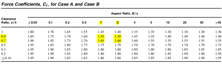
Figure 14. Net force coefficient, \( {C}_{f} \), values from Figure 29.3-1 of ASCE 7-16 for solid signs.
By interpolate the highlighted values to get \( {C}_{f} \) from our \( B/s \) and \( s/h \), we get:
\( {C}_{f} = 1.5706 \)
Design Wind Pressures – Tilt Angle > 45°
In calculating wind load on solar panels with tilt angle > 45°, we will be using Equation (2), hence, the wind loads on ground-mounted solar panels:
\({q}_{h} = 18.256 psf\)
\( G = 0.85\)
\( {C}_{f} = 1.5706 \)
\(p = {q}_{h}G{C}_{f} = (18.256)(0.85)(1.5706) = 24.372 psf\)
\(p = 24.372 psf\)
Therefore, the wind loads on ground-mounted solar panels when applied: 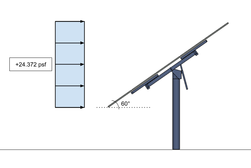
Figure 15. The design wind pressure for the solar panel as solid sign – applied to the vertical projection.
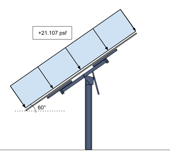
Figure 16. The converted design wind pressure for the solar panel as solid sign – applied to the surface of the solar panel.
The wind calculations can all be performed using SkyCiv Load Generator for ASCE 7-16 (solar panel wind load calculator). Users can enter the site location to get the wind speed and terrain data, enter the solar panel parameters and generate the design wind pressures. With the standalone version, you can streamline this process and get a detailed wind load calculation report for solar panels!
Snow Loading
For areas that experience snow, snow loads on solar panel should also be considered. To calculate snow loads for our solar panel, we will be using Chapter 7 of ASCE 7-16. We will be consider the solar panel structure as building with monoslope roof and we will only consider the balanced snow load (sloped roof snow load). The formulas to determine the snow load for our solar panel are as follows:
To calculate the flat roof snow load \({p}_{f} \):
\({p}_{f} = 0.7{C}_{e}{C}_{t}{I}_{s}{p}_{g} \) (7)
Where:
\({C}_{e} \) = exposure factor
\({C}_{t} \) = thermal factor
\({I}_{s} \) = importance factor for snow load
\({p}_{g} \) = ground snow load, in psf
To calculate the sloped roof snow load \({p}_{s} \):
\({p}_{s} = {C}_{s}{p}_{f} + {p}_{r} \) (8)
Where:
\({C}_{s} \) = roof slope factor
\({p}_{r} \) = rain-on-snow surcharge load
Exposure Factor, \({C}_{e} \)
The Exposure Factor, \({C}_{e} \), can be determined from Table 7.3-1 of ASCE 7-16 based on the Surface Roughness and Exposure of Roof. From the satellite image of the location that we got from Google Maps, we can classify that the location is Surface Roughness C (open terrain with scattered obstructions that have heights generally less than 30 ft) and with the assumption that the solar panels are fully exposed and without obstructions. Hence, the Exposure Factor, \({C}_{e} \), of the structure is equal to 0.9.
Thermal Factor, \({C}_{t} \)
The Thermal Factor, \({C}_{t} \), can be determined from Table 7.3-2 of ASCE 7-16 based on the thermal condition of the structure during winter. From the table, we can classify our solar panel as “Unheated and open air structures.” Therefore, the corresponding of Thermal Factor, \({C}_{t} \), is for the structure is equal to 1.2.
Importance Factor for Snow Load, \({I}_{s} \)
The Importance Factor for Snow Load, \({I}_{s} \), can be determined from Table 1.5-2 of ASCE 7-16 based on the Risk Category of the structure. Since the structure is classified as Risk Category I, from the table, \({I}_{s} \) is equal to 0.8.
Ground Snow Load, \({p}_{g} \)
The Ground Snow Load, \({p}_{g} \), can be determined from Figure 7.2-1 of ASCE 7-16 as shown below. From this figure, the ground snow load, \({p}_{g} \) for our solar panel is equal to 10 psf.
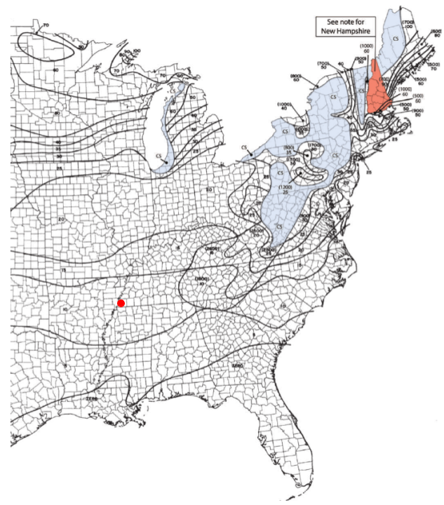
Figure 17. Ground snow load map from Figure 7.2-1 of ASCE 7-16 with red dot to indicate the location of our solar panel.
SkyCiv also automates the ground snow load calculations with a few parameters. Try our Solar Panel Wind Load Calculator
Flat Roof Snow Load, \({p}_{f} \)
From the parameters above, we can already calculate the flat roof snow load, \({p}_{f} \), using Equation (7):
\({p}_{f} = 0.7{C}_{e}{C}_{t}{I}_{s}{p}_{g} \)
\({p}_{f} = 0.7(0.9)(1.2)(0.8)(10) = 6.048 psf \)
\({p}_{f} = 6.048 psf \)
Roof Slope Factor, \({C}_{s} \)
The roof slope factor can be calculated from Figure 7.4-1 of ASCE 7-16 depending on the tilt angle, the obstruction below the roof surface, and the value of thermal factor \({C}_{t} \). For our solar panel, we will assume that our solar panel is classified as “Slippery surface.” Since the thermal factor \({C}_{t} \) is equal to 1.2, we can already interpolate the value of \({C}_{s} \) from 7-2c. From the graph, the known values are:
\({C}_{s} = 1.0 \) for 15°
\({C}_{s} = 0.0 \) for 70°
Interpolating these values we can get:
\({C}_{s} = 0.727 \) for 30°
Therefore, \({C}_{s} = 0.727 \) for our solar panel.
Rain-on-snow Surcharge Load, \({p}_{r} \)
An additional 5 psf rain-on-snow surcharge load, \({p}_{r} \), should be considered for locations where \({p}_{g} \) is less than or equal to 20 psf but not zero, for all roofs with slope angle (in degrees) less than \( W/50 \) degrees where \( W \) is the horizontal distance from eave to ridge. The value of \({p}_{r} \) only applies to the sloped roof (balanced) load case. For this example:
\(W = 13.33 cos 30° = 11.544 ft \)
\( W/50 =0.231° \)
Since \({p}_{g} = 10 psf \) but tilt angle 30° is greater than \( W/50 =0.231° \), \({p}_{r} \) can be neglected and is equal to 0.0
Sloped Roof Snow Load, \({p}_{s} \)
From Equation (8), we can calculate the sloped roof snow load \({p}_{s} \):
\({p}_{s} = {C}_{s}{p}_{f} + {p}_{r} \)
\({p}_{s} = (0.727)(6.048) + 0.0 = 4.397 psf \)
\({p}_{s} = 4.397 psf \)
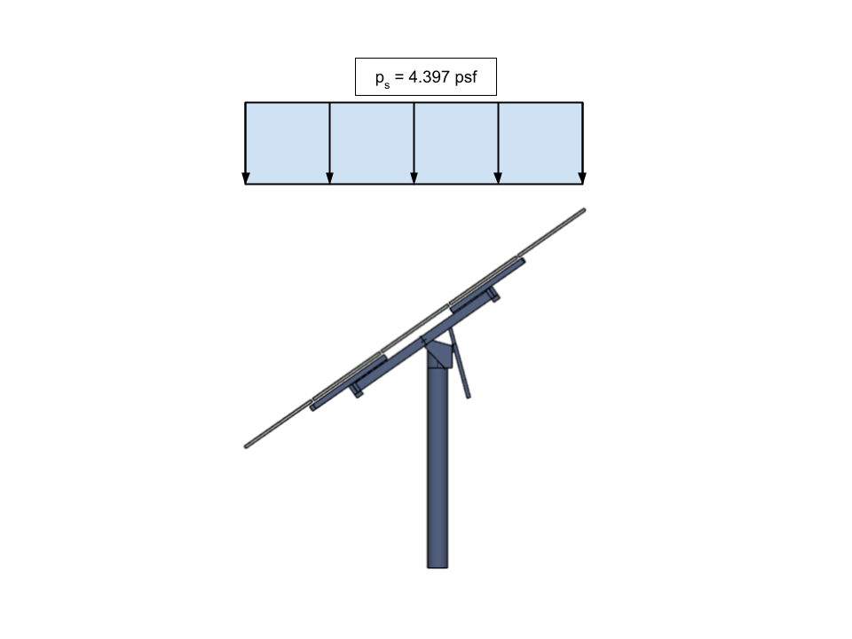
Figure 18. The calculated balanced snow load (sloped roof snow load) for the solar panel applied on the horizontal projection of the structure.
Note that \({p}_{s} \) is applied on the horizontal projection of the structure. We will need to convert this value to an equivalent sloped pressure load so we can apply it to our model.
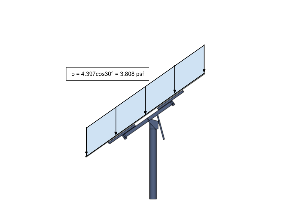
Figure 19. The converted balanced snow load (sloped roof snow load) for the solar panel to be applied to our model.
The snow load calculations can also be performed in SkyCiv Load Generator for ASCE 7-16. However, it is only available in our standalone version and Professional Account.
SkyCiv Load Generator
Using the SkyCiv Load Generator, you can get wind loads and snow loads on ground-mounted solar panels with just a few clicks and inputs. When you purchase the standalone version or signup for Professional account, you will be able to generate the detailed wind and snow calculations report for your solar panel project!
You can check the detailed wind and snow load report for the solar panel thru these links:
Furthermore, you can also create your own solar panel wind load calculator using the SkyCiv Load Generator API just like how we’ve created a solution for one of our clients. With just a few inputs, it will automatically design the solar panel system for you. You can check our API documentation through this link.
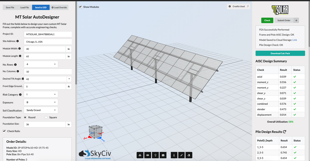
Figure 20. Our custom solution for solar panel created for MT Solar using SkyCiv API.
For additional resources, you can use these links:
- Introduction to SkyCiv Load Generator
- ASCE 7-16 Wind Load Calculations (Solar Panels)
- ASCE 7 Snow Load Calculations
- How to Calculate and Apply Roof Snow Drift Loads w/ ASCE 7-10
- Calculating Roof Snow Loads w/ ASCE 7-10

Structural Engineer, Product Development
MS Civil Engineering
References:
- Coulbourne, W. L., & Stafford, T. E. (2020, April). Wind Loads: Guide to the Wind Load Provisions of ASCE 7-16. American Society of Civil Engineers.
- American Society of Civil Engineers. (2017, June). Minimum design loads and associated criteria for buildings and other structures. American Society of Civil Engineers.
- Google Maps
- MT Solar