Introduction
In the following tutorial, we’ll explore how to create a Cold-Formed Steel Structure in Structural 3D, beginning with the modeling, analysis, and designing of a structure.
We’ll show step-by-step on how to create nodes, members, sections, materials, supports, loads, and load combinations in this cold formed steel design example.
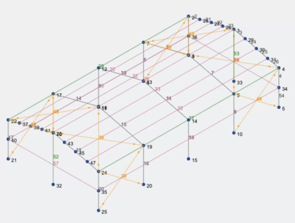
You have to open Structural 3D from your SkyCiv dashboard and create a new project, in this tutorial, we will be working on meters, so you can modify the units by going to settings > unit system and selecting metric.
Nodes Creation
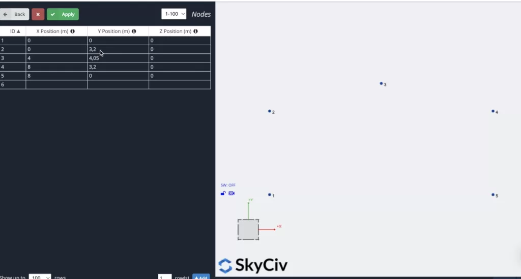
To create the nodes we can go to nodes > open datasheet and define them using coordinates from Excel, after we put the node coordinates we will see how all the nodes are created on the canvas. Use the coordinates shown in the following image.
Member creation
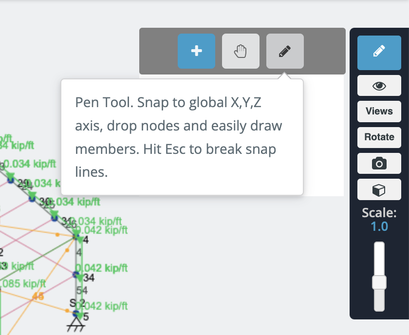
There are different ways to create members, using the form, and datasheet, but in this example, we will be using the pen tool for the member creation, you can activate the pen tool going to the right panel > pen > pen tool.
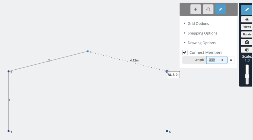
After we have the pen tool selected we can start to create all the frame members by clicking on the nodes that we created in the previous step, as shown in the next image:
Frame Duplication
To avoid the creation of more nodes and members we will duplicate the frame that we created in the previous steps. To achieve this we need to select the whole frame by doing right click on the canvas > Select all or hit Ctrl + A on your keyboard. After we select the whole frame we can go to Edit > Operations > Repeat or hit Ctrl + D.
A form will appear on the screen, we will use the information shown in the following image:
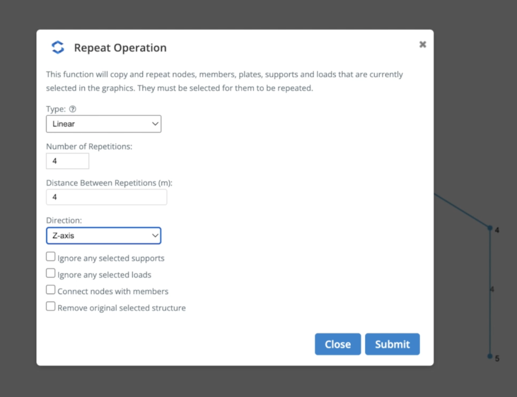
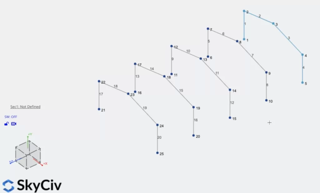
We used 4 linear repetitions every 4 meters along the Z-axis. The result should look as shown in the following image:
Sections and Materials
The next step will be the creation of sections and materials, in this example, we will be using the Section Builder module to create our sections, to access the Section Builder module we need to go to Sections > Builder. Once the section builder is opened, we can select sections from the database, in this case, we will select Database Shapes > American > AISI > C-Section W Lips (I – 1). It’s important to mention that when we use section builder, the materials will be already assigned to the sections, in this case, we can see that Structural Steel is selected.
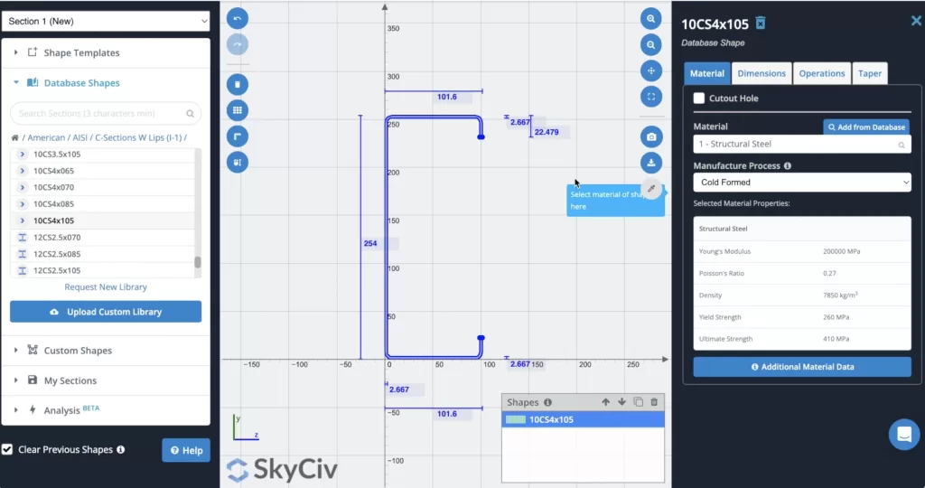
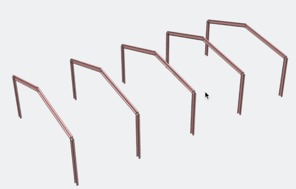
After we select our section we can calculate it (Optional) to obtain its properties, after we chose the correct section we can click on Submit. By default, when we have members without sections defined, the new section will be assigned to them. If we open the 3D renderer we will see the following result.
Purlins Creation
We will create more members for our structure, in this case, we will add purlins on the roof. At first, we will split the members 2 and 3 into 4 parts each, to achieve this we can select those 2 members > Right Click > Split Members > Divide Member Into Equal Parts: 4 > Click on Split. The result will look like this:
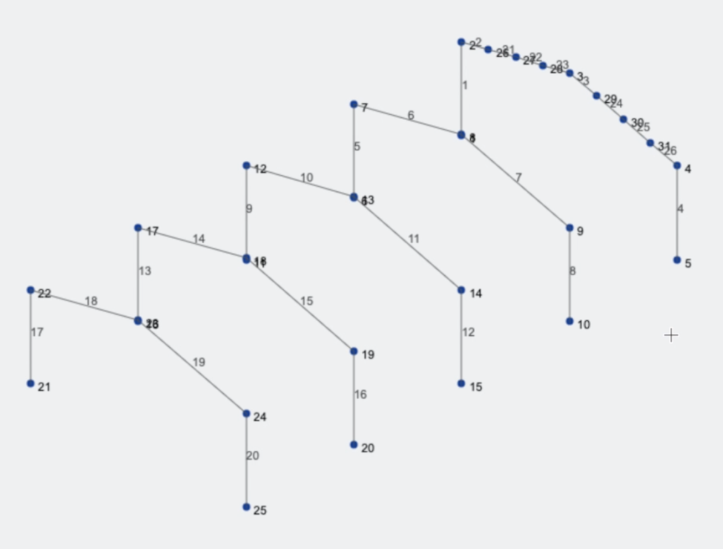
The next step will be to create a new member using the pen tool from nodes 24 to 4, after we create this member we have to select it and then hit Ctrl + C, select the nodes we just created, and hit Ctrl + V. The result should look like this.
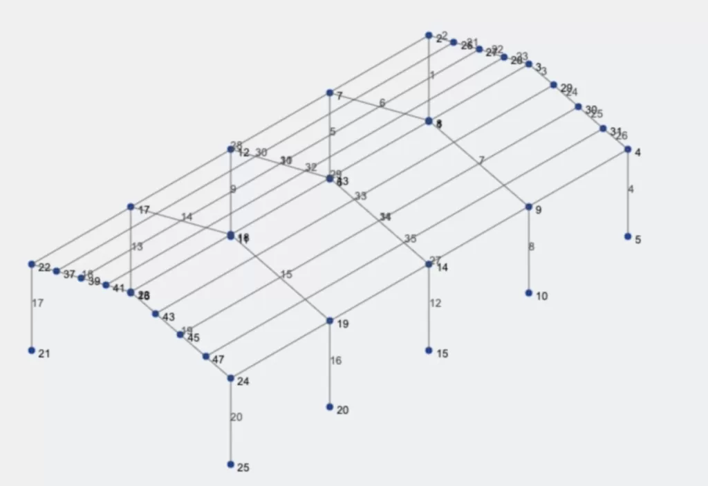
Bracing Members Creation
We will proceed with the bracing members creation, we will add truss elements at the start and the end of the structure, and we will use the pen tool for this task, when you finished the creation of the X bracing members the result should look like this.
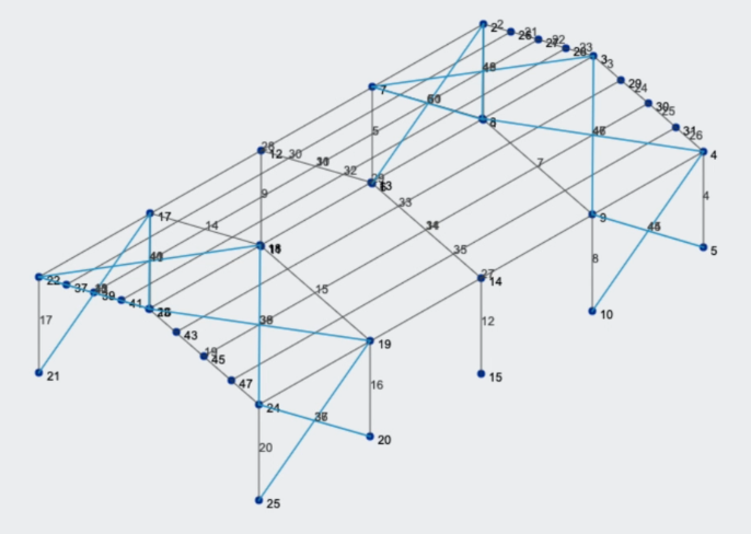
We need to convert these elements to Truss elements, so we have to Select them > in Multi Edit Members we will Click on Truss > Click on Apply. You’ll see that now all the bracing members are trusses and will not transmit moments to the other elements where they are connected.
Girts and Columns
We will create the remaining elements of our structure, in this case, we will create columns from the ground to node 23, and repeat the process with node 3. Also, we will add girts in the mid portion of the existing columns. The result should look like this:
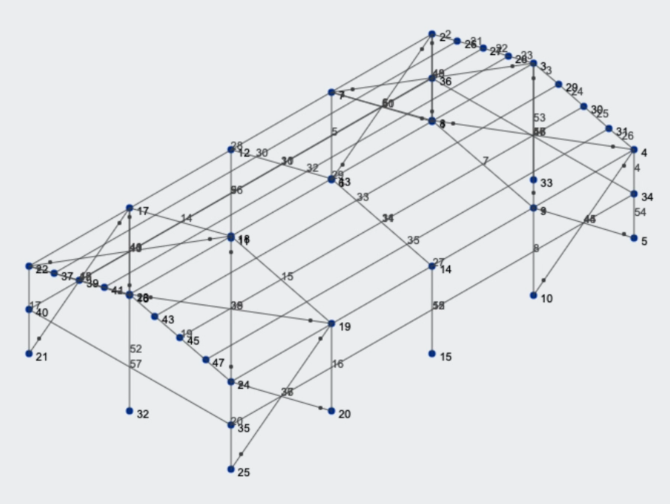
Assigning Sections to Members
We need to create more sections and materials in order to assign them to our new elements, repeating the Sections and Materials step shown before you need to create the following materials:
- 8CS2x070
- 6CS2.5×059
- 2.5LS2.5×0.90
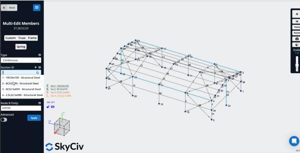
When we have these sections on our model, we have to assign them to our members, we can select some members, then, in the left panel, you can modify de Section ID, and select in this case section number 2 – 8CS2x070 – Structural Steel and Click on Apply, as shown in the following image:
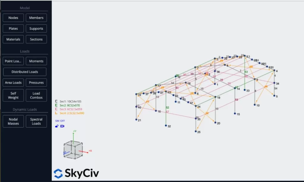
You can repeat this process and assign Sec 3 to the purlins and girts, and Sec 4 to all the X bracing members, the result should look like this:
Loads Assignment
We will apply some area loads to our structure, we will use live loads on the roof, wind loads on a side of the structure, and a point dead load on node number 8. To apply live loads you can go to Area Loads and put the following data:
- Type: One-Way
- Corner Node IDs: 22, 23, 3, 2
- Pressure magnitude: -0.25
- Load Direction: Global Y-axis
- Column/Beam Direction: 22,23
- Load Group: LG
After you defined all the properties you can click on Apply.
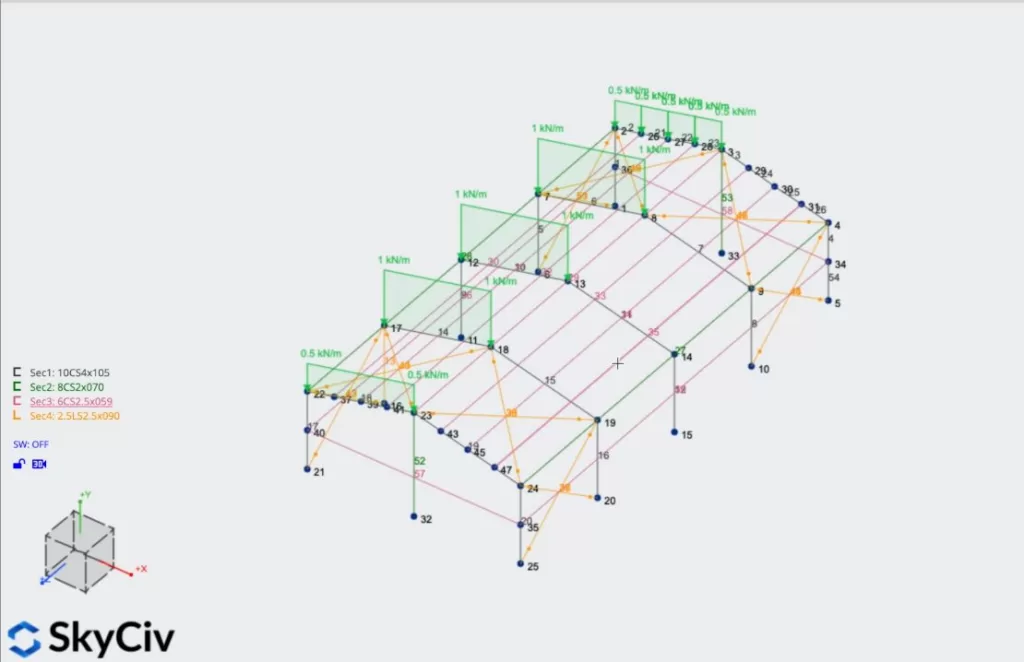
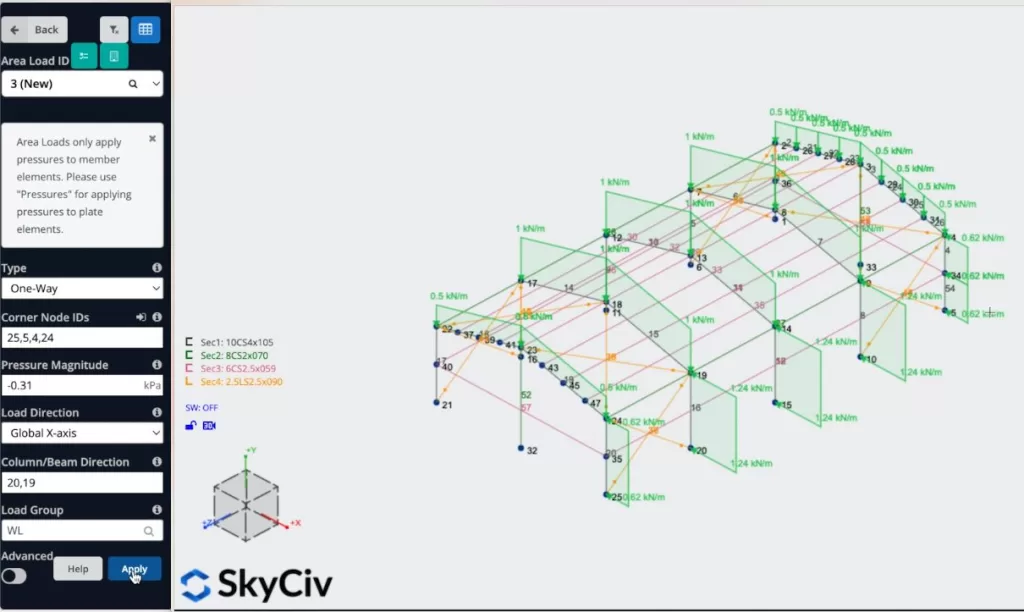
We can now repeat the process with the other section of the roof using the same properties used before. We can also apply the wind area load on the side of the structure using the following properties:
Finally, we will apply a point load, we should select Point Load > put node number 8, Y magnitude = -1.5 KN > hit on Apply.
Supports Assignment
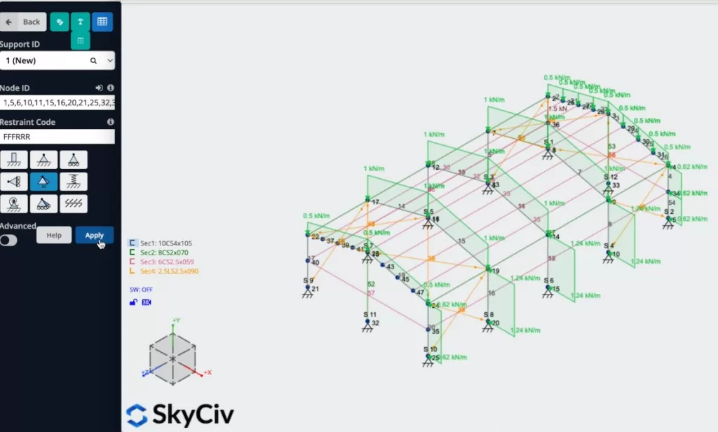
To add supports to our structure we have to select all the ground nodes, then go to Supports > Double Click on the Node ID field (If you have your nodes selected) > Select 3D Pin Support > Apply. After you create all your supports they should appear on your mode
Load Combinations
We can define know our load combinations, we need to click on Load Combos > Design Codes, and a window containing the design codes from the database should appear, we will use the ASCE 7 – ASD code for this example and we will click on Display.
When the load combinations appear, we need to ensure that the names that we use to define our area and point loads correspond to loads of the code: for example, our Dead load DL should be equal to Dead: dead, LG = Live: live, WL = Wind: wind.
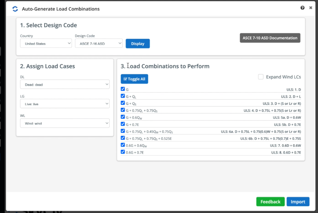
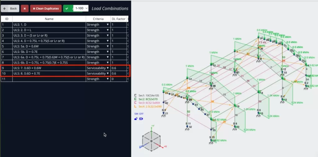
When you have your loads defined you can click on Import and all the load combinations should appear on the datasheet. For this example we will modify the last two load combinations from Strength to Serviceability, the reason is that we need to define serviceability loads to make some calculations to design the structure, so the program will ask for them.
Self-weight Activation
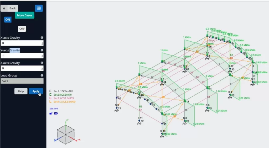
We will activate the self-weight of our members so when we solve our structure the load of the elements will be considered, to do this we just need to click on Self Weight > Click on On > Apply. We need to verify that the value in our vertical axis is equal to -1.
Solving the Model
After we finished the modeling of the structure, we can proceed to solve our Structure, we can do this by clicking on Solve > Linear Static, and it will take us to a new window where we will be able to see all the results of the structure.
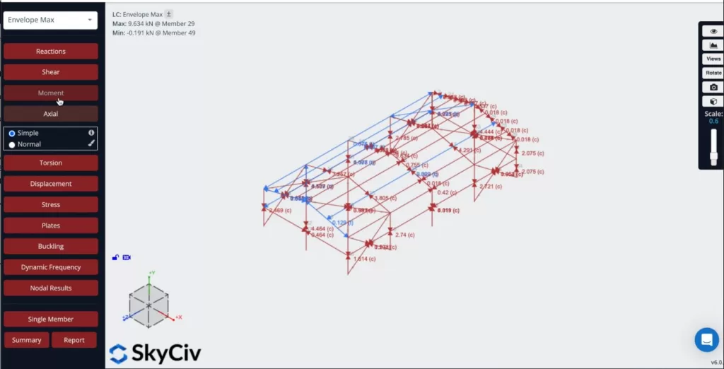
We can also create reports from the analysis, we can click on Report, customize the report as needed, specify what load combinations to include, etc. We can click on Create report when we finish the configuration.
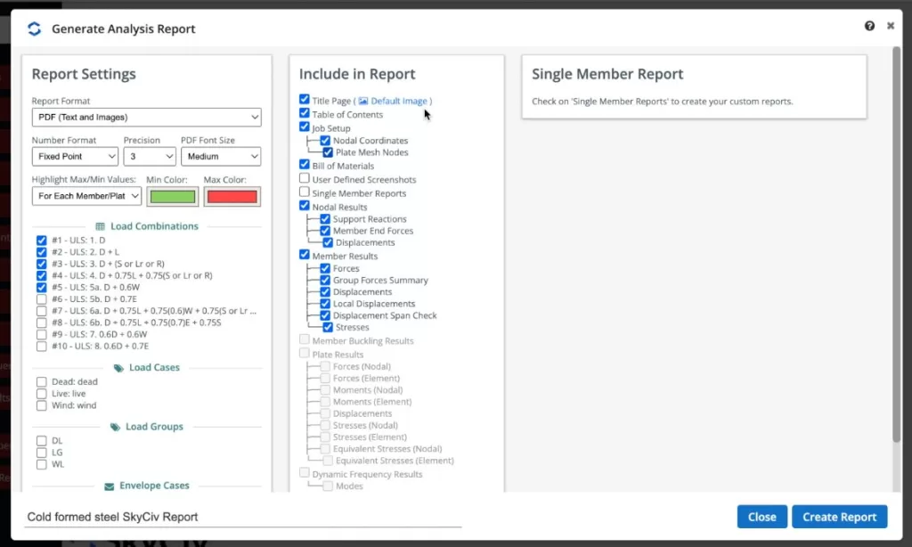
When the program finishes the report we can view the results of our structure, we can also download that report as PDF or HTML.
Designing the Structure
We can now run the design checks of our structure, we can click on Design Check > Start New Code > Member Design > Select AISI S100-12 ASD > Start. If you receive a message that says that the metric system is not supported, you can go to your model Settings > Unit System > Select Imperial, run the model again, and run the design check. Once, everything is correct, you can click on Check And you’ll see the results of the members.
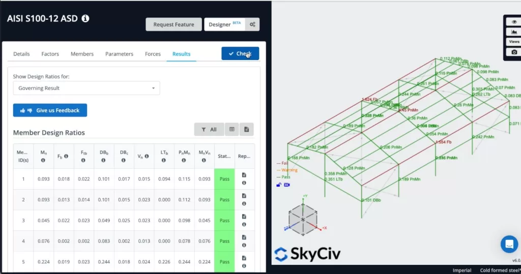
If some members don’t pass, we can see the report for each member and it will show us all the hand calculations.
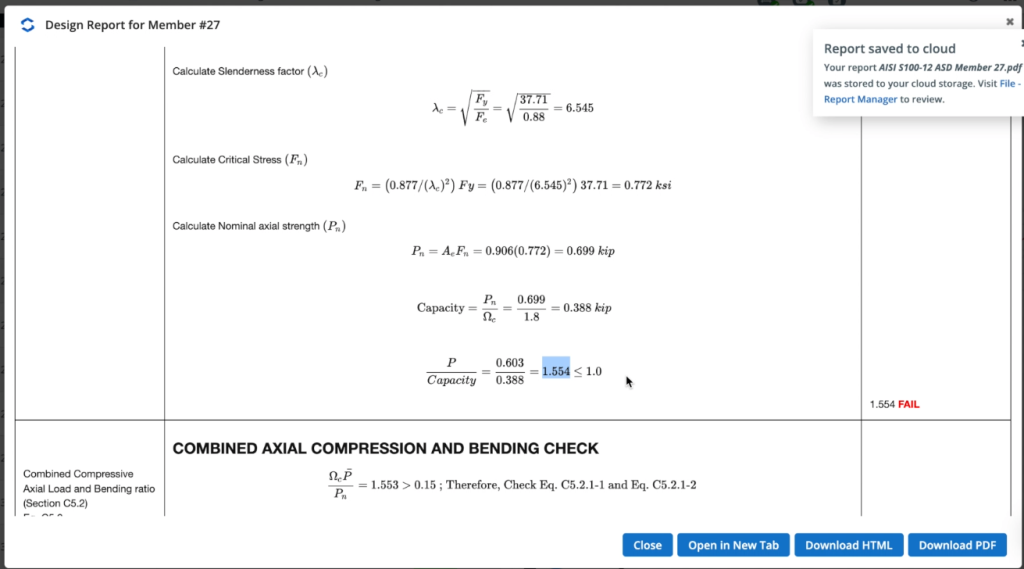
We can see what is not working and we can go to our model and modify our structure until it passes all the checks.
FAQ
1. How can I see the section properties of my cold-formed section?
You can use Section Builder to see all the properties of your section, including section of inertia, section modulus, Shear properties, etc.
After you select your section, you can click on Calculate and that’s it.
2. Can I define my own Load Combinations?
Yes, you can define your load combinations, take a look at the following tutorial Load combinations.
3. Why am I getting a message saying that my section is not supported when using Member Design?
The reason is that we are continuously adding more sections to be designed, and some design codes are being updated with these changes, so you may be using sections that are not supported yet.


