AISC Connection Design Example
This tutorial provides an AISC connection design example. Shear connections between I-shaped sections are some of the most common connections in steel design. To help understand the required design checks in accordance with AISC 360, this article will use a design example to explain them. With this type of connection, we can also quickly get to the results of this example through the use of the SkyCiv Connection Design module. Make sure to check out the additional article on designing a moment connection.
The calculations presented here will be using the Allowable Stress Design (ASD) method. If you aren’t familiar with the difference between ASD and LRFD in structural design, make sure to check out our video explaining this.
AISC Connection Design Manual
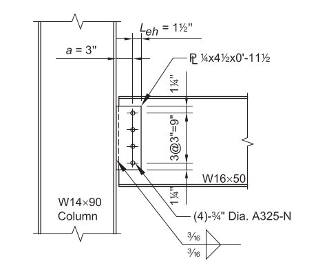
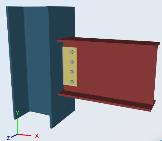
For this example, we are going to be evaluating the capacity of a single-plate connection between a W16x50 beam and a W14x90 column using the dimensions and bolts shown below. This connection needs to be able to support the beam end reactions.
Service Level Loads & Material:
Reaction from Dead Load (RD) = 8.0 kips
Reaction from Live Load (RL) = 25.0 kips
Plate Material: ASTM A36, Fy = 36 ksi, Fu = 58 ksi
Beam and Column Material: ASTM A992, Fy = 50 ksi, Fu = 65 ksi
Beam and Column Geometry:
Beam: W16x50; tw = 0.380 in, d = 16.3 in., t f = 0.630 in
Column: W14x90; tf = 0.710 in.
Shear Plate: 1/4 in thick; 4 1/2 in x 11 in dimensions
Fixtures (Bolts and Welds):
(4) – 3/4-in.-diameter ASTM A325-N bolts in standard holes
70-ksi electrode fillets
Load Calculation:
LRFD:
Ultimate Reaction (Ru) = 1.2(8.0 kips) + 1.6(25.0 kips) = 49.6 kips
ASD:
Allowable Reaction (Ra) = 8.0 kips + 25 kips = 33.0 kips
Using the SkyCiv Connection Design software, the different parts of the connection will now be checked in accordance with the Section J checks of AISC 360:
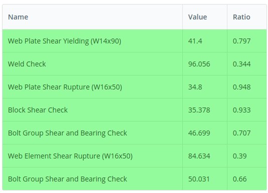
Web Plate Shear Yielding (W14x90)
Allowable Shear Capacity:Allowable Shear Capacity: Ω = 1.5
Rav = (0.6 Fy Agv / Ω) = [ 0.6 (36 ksi) (0.25 in) 11.5 in / 1.5 ] = 41.4 kips
Design capacity ratio, DCR:
required shear, Rv = 33.0 kips
overall capacity, Rav = 41.4 kips
DCR = (33.0 / 41.4) = 0.797, OK
Web Plate to W14x90 Flange, Weld Strength
Strength of Fillet Welds: Ω = 2.0
Weld Size, t = 0.1875 in
Fnw = 0.6 FEXX
Fnw = 0.6 FEXX [ 1.0 + 0.5 sin^1.5 θ ]
θ = the angle which the load makes with the weld axis
= 90, for transversely loaded welds
= 0, for longitudinally loaded welds
Strength per unit size of weld:Strength per unit size of weld:
Allowable weld stress, Faw = [ 0.6 (70) / 2.0 ] = 21 ksi
transverse length, lt = 0 in
longitudinal length, ll = 23 in
total effective length, l = lt (1.5) + ll (1.0) = 0 (1.5) + 23 (1.0) = 23 in
(Ra / t) = 483 kips / in
Effective size (throat) of fillet weld, a:
0.707 = the cosine or sine of 45deg
a = (0.707) t = 0.133 in
Ra = (Ra /t) t = 483 (0.133 in) = 64.2 kips
Design capacity ratio, DCR:
required load, R = 33.0 kips
overall capacity, Ra = 64.2 kips
DCR = (33.0 / 64.2) = 0.514, OK
Web Plate Shear Rupture (W16x50)
Allowable Shear Capacity: Ω = 2.0
Calculation of net depth:
total length of bolt hole(s) = 0.875 in (4) = 3.5 in
net depth, dnet = 11.5 in − [ 0.875 in (4) ] = 8.0 in
Rav = (0.6 Fy Anv / Ω) = [ 0.6 (58 ksi) (0.25 in) 8 in / 2.0 ] = 34.8 kips
Design capacity ratio, DCR:
required shear, Rv = 33.0 kips
overall capacity, Rav = 34.8 kips
DCR = (33.0 / 34.8) = 0.948, OK
Web Plate to W16x50 Web, Block Shear Rupture Strength
Block Shear Strength: Ω = 2.0
(Ra / Ω) = (Ubs Fu Ant / Ω) + min [ 0.6 Fy Agv , 0.6 Fu Anv ] / Ω
Tension Rupture Component: Ubs=1.0 (uniform tension)
(Ubs Fu Ant / Ω) = [ 1.0 (58 ksi) (1.0625 in) (0.25 in) / 2.0 ] = 30.8 kips/in (0.25 in) = 7.7 kips
Shear Yielding Component: 0.6 Fy Agv
(0.6 Fy Agv / Ω) = [ 0.6 (36 ksi) (10.25 in) / 2.0 ] (0.25) = 110.7 kips/in (0.25 in) = 27.7 kips
Shear Rupture Component: 0.6 Fu Anv
(0.6 Fu Anv / Ω) = [ 0.6 (58 ksi) (7.1875 in) / 2.0 ] (0.25 in) = 125.1 kips/in (0.25 in) = 31.3 kips
Total Block Shear Capacity:Total Block Shear Capacity:
(Ra / Ω)= 7.7 kips + min [ 27.7 kips , 31.3 kips ] = 35.4 kips
Design capacity ratio, DCR:
required shear, Rv = 33.0 kips
overall capacity, Rav = 35.4 kips
DCR = (33.0 / 35.4) = 0.933, OK
Web Plate to W16x50 Web, Bolt Group Shear, and Bearing Check
1. Shear Strength of Bolts: Ω = 2.0
Bolt Diameter = 0.768 in
Nominal Shear Strength, Fnv = 54 ksi
Nominal Shear Strength (per bolt), Rnv = 0.6 Fnv Ab = 0.6 (54 ksi) 0.463 in^2 = 25.0 kips
(Rnv / Ω) =12.5 kips / bolt
2. Bearing Strength of Standard Bolt Holes: Ω = 2.0
(Ignoring bolt hole deformation at service load level)
edge distance, le = 0.84 in
(clear)distance to adjacent hole, lc = 2.19 in
Since edge distance is less than the adjacent distance to the next bolt hole, edge distance will control:
(Rnb / Ω) = (1.2 lc t Fu / Ω) ≤ (2.4 d t Fu / Ω)
For the outer bolt (tearout), lc = 0.84 in:
Rnb = 1.2 lc t Fu =1.2 (0.84 in) 0.25 in (58 ksi) = 18.4 kips
(Rnb / Ω) = 9.2 kips
For the inner bolt (tearout), lc = 2.19 in:
Rnb = 1.2 lc t Fu = 1.2 (2.19 in) 0.25 in (58 ksi) = 47.6 kips
(Rnb / Ω) = 23.8 kips
For overall bearing (bolt hole elongation):
Rnb = 2.4 d t Fu = 2.4 (0.8125 in) 0.25 in (58 ksi) = 33.4 kips
(Rnb / Ω) = 16.7 kips
Bearing will control over bolt shear since 9.2 kips < 12.5 kips
3. Capacity of Bolt Group
Considering the minimum among: bolt shear capacity, bearing and tearing in inner and outer bolt holes.
a). Capacity of outer bolt (as established above):
(outer bolt) , Rab = 9.2 kips / bolt
b). Capacity of inner bolt (as established above):
(inner bolt) , Rab = 12.5 kips / bolt
c). Capacity of the bolts as a group: sum of the capacities a). and b).
Rab = 1 (9.2 kips / bolt) + 3 (12.5 kips / bolt) = 46.7 kips
Design capacity ratio, DCR:
required shear, R = 33.0 kips
overall capacity, Rab = 46.7 kips
DCR = (33.0 / 46.7) = 0.707, OK
Web Element Shear Rupture (W16x50)
Allowable Shear Capacity: Ω = 2.0
Calculation of net depth:Calculation of net depth:
total length of bolt hole(s) = 0.875 in (4) = 3.5 in
net depth, dnet =16.3 − [ 0.875 in (4) ] = 12.8 in
Rav = (0.6 Fy Anv / Ω) = [ 0.6 (58 ksi) (0.38 in) 12.8 / 2.0 ] = 84.6 kips
Design capacity ratio, DCR:
required shear, Rv = 33.0 kips
overall capacity, Rav = 84.6 kips
DCR = (33.0 / 84.6) = 0.390, OK
Web Element, Bolt Group Shear and Bearing Check
1. Shear Strength of Bolts: Ω = 2.0
Bolt Diameter = 0.768 in
Nominal Shear Strength, Fnv = 54 ksi
Nominal Shear Strength (per bolt), Rnv = 0.6 Fnv Ab = 0.6 (54 ksi) 0.463 in^2 = 25.0 kips
(Rnv / Ω) =12.5 kips
2. Bearing Strength of Standard Bolt Holes: Ω = 2.0
(Ignoring bolt hole deformation at service load level)
edge distance, le = 0.84 in
(clear) distance to adjacent hole, lc = 2.19 in
Since edge distance is less than the adjacent distance to the next bolt hole, edge distance will control.
(Rnb / Ω) = (1.2 lc t Fu / Ω) ≤ (2.4 d t Fu / Ω)
For the outer bolt (tearout), lc = 0.84 in:
Rnb = 1.2 lc t Fu = 1.2(0.84 in) 0.38 in (58 ksi) = 27.9 kips
(Rnb / Ω) = 13.9 kips
For the inner bolt (tearout), lc = 2.19 in:
Rnb = 1.2 lc t Fu = 1.2 (2.19 in) 0.38 in (58 ksi) = 72.3 kips
(Rnb / Ω) = 36.2 kips
For overall bearing (bolt hole elongation):
Rnb = 2.4 d t Fu = 2.4 (0.8125 in) 0.38 in (58 kksi) = 50.8 kips
(Rnb / Ω) = 25.4 kips
Bolt shear will control over bearing since 12.5 kips < 13.9 kips
3. Capacity of Bolt Group
Considering the minimum among: bolt shear capacity, bearing and tearing in inner and outer bolt holes.
a). Capacity of outer bolt (as established above):
(outer bolt), Rab = 12.5 kips / bolt
b). Capacity of inner bolt (as established above):
(inner bolt), Rab = 12.5 kips / bolt
c). Capacity of the bolts as a group: sum of the capacities a). and b)
Rab = 12.5 kips + 3(12.5 kips) = 50.0 kips
Design capacity ratio, DCR:
required shear, R = 33.0 kips
overall capacity, Rab = 50.0 kips
DCR = (33.0 / 50.0) = 0.660, OK
Alternatively, if you are already an experienced engineer and are familiar with the design process for a simple shear connection, the process can be substantially shortened, thanks to the design tables offered in the AISC 360 Design Manual:
Bolt Shear, Weld Shear, and Bolt Bearing, Shear Yielding, Shear Rupture, and Block Shear Rupture of the Plate
Try four rows of bolts, 1/4-in. plate thickness, and 3/16-in. fillet weld size.
From AISC Manual Table 10-10a:
LRFD
Rn = 52.2 kips > 49.6 kips, OK
ASD
Rn = 34.8 kips > 33.0 kips = Ra, OK
Bolt Bearing for Beam Web
Block shear rupture, shear yielding and shear rupture will not control for an un-coped section.
From AISC Manual Table 10-1, for an un-coped section, the beam web available strength is:
LRFD
Rn = 351 kips/in. (0.380 in.) = 133 kips > 49.6 kips = Ru, OK
ASD
Rn = 234 kips/in. (0.380 in.) = 88.9 kips > 33.0 kips = Ra, OK
The AISC connection design example shown above is done under ASD (the pdf version is available here: ASD Connection Design Report.pdf ). Similarly, the LRFD version example can be found in this link: LRFD Connection Design.pdf.

REFERENCES:
AISC 360 Specification Structural Steel Buildings
AISC Design Examples v14.1 (EXAMPLE II.A-17, pages IIA-60 to 61)
SkyCiv Connection Design Software: https://skyciv.com/structural-software/connection-design/