If you read our previous article, AISC 360: Shear Connection Design, you would have a good sense of how simple connections are designed under the AISC 360. While shear connections are common, they don’t pose the same design challenge as moment connections. In this article, we use an example moment connection between two I-shaped members to go over the various design criteria that are required to be satisfied. With this type of connection, we can also quickly get to the results of this example through the use of the SkyCiv Connection Design module.
Similar to the shear connection example, the calculations presented here will be using the Allowable Stress Design (ASD) method. If you aren’t familiar with the difference between ASD and LRFD in structural design, make sure to check out our video explaining this.
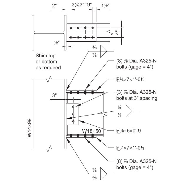
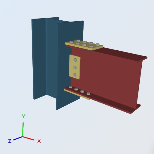
In this exmaple, we are going to be evaluating the capacity of a Bolted Flange-Plated Fully-Restrained (FR) Moment connection between an W18x50 beam and an W14x99 column using the dimensions, welds, and loads shown below. This connection needs to be able to support not just the beam end vertical reactions but also the developed end moments. You may notice that the main difference lies in the connection of the beam flanges onto the supporting column (flange).
Given:
Service Level Loads & Material:
Vertical Shear from Dead Load (VD) = 7.0 kips
Vertical Shear from Live Load (VL) = 21.0 kips
Moment from Dead Load (MD) = 42.0 kip-ft
Moment from Live Load (ML) = 126.0 kip-ft
Plate Material: ASTM A36, Fy = 36 ksi, Fu = 58 ksi
Beam and Column Material: ASTM A992, Fy = 50 ksi, Fu = 65 ksi
Beam and Column Geometry:
Beam: W18x50; bf = 7.50 in, tf = 0.570 in, d = 18.0 in, tw = 0.355 in, Sx = 88.9 in^3
Column: W14x99; bf = 14.6 in, tf = 0.780 in, d = 14.2 in, tw = 0.485 in, kdes = 1.38 in
Flange Plate: 3/4 in thick; 7.0 in x 12.5 in dimensions
Web Plate: 3/8 in thick; 5.0 in x 9.0 in dimensions
Fixtures (Bolts and Welds):
Flange: (8) – 7/8-in.-diameter ASTM A325-N bolts in standard holes
Web Plate: (3) – 7/8-in.-diameter ASTM A325-N bolts in standard holes
70-ksi electrode fillets
Load Calculations:
LRFD Loads (Reference only):
Ultimate Vertical Reaction (Ru) = 1.2 (7.0 kips) + 1.6 (21.0 kips) = 42.0 kips
Ultimate Moment (Mu) = 1.2 (42.0 kip-ft) + 1.6 (126.0 kip-ft) = 252.0 kip-ft
ASD Loads:
Allowable Vertical Reaction (Ra) = 7.0 kips + 21 kips = 28.0 kips
Allowable Moment (Ma) = 42.0 kip-ft + 126 kip-ft = 168.0 kip-ft
Solution based on SkyCiv Connection Design Software:
ERRATUM: The flange plate width in this example was 7.0 in but the width used in the calculations is 7.50 in, hence the difference in values.
Flange Plate to W14x99 Flange, Weld Strength
Strength of Fillet Welds, Ω = 2.0
Weld Size, t = 0.375 in, Fnw = 0.6 FEXX
Fnw = 0.6 FEXX [ 1.0 + 0.5 sin1.5 (θ) ]
Where, θ = the angle which the load makes with the weld axis
= 90, for transversely loaded welds
= 0, for longitudinally loaded welds
Strength per unit size of weld:
Allowable weld stress, Faw = 0.6 (70ksi) / 2.0 = 21 ksi
transverse length, lt = 7 in
longitudinal length, ll = 0 in
total effective length, l = lt (1.5) + ll (1.0) =10.5 in
(Ra / t) = 220.5 kips / in
Effective size (throat) of fillet weld, a:
0.707 = the cosine or sine of 45 degrees
a = (0.707) t = 0.265 in
Ra = (Ra / t) t = 220.50 (0.265 in) 2 = 116.9 kips
Design capacity ratio, DCR:
required load, R = 107.5 kips
overall capacity, Ra = 116.9 kips
DCR = (107.5 / 116.9) = 0.919, OK
Column Local Checks
Flange Force, Paf = [ 168.0 kips-ft (12 in/ft) ] / (18.0 in + 0.75in) = 107.5 kips
- Web Local Yielding, Ω = 1.5
Rn / Ω = [ Fyw tf (5k + lb) ] / Ω = 50ksi (0.485in) [ 5(1.38in) + 0.75in ] / 1.5 = 123.7 kips
Design capacity ratio, DCR:
Flange Force, Paf =107.5 kips
Overall capacity, Ra=123.7 kips
DCR = (107.5 / 123.7) = 0.869, OK
- Flange Local Bending, Ω = 1.67
Rn / Ω = [ 6.25 Fy tf2 ] / Ω = [ 6.25 (50ksi) (0.78in)2 ] / 1.67 = 113.8 kips
Design capacity ratio, DCR:
Flange Force, Paf = 107.5 kips
Overall capacity, Ra= 113.8 kips
DCR = (107.5 / 113.8) = 0.944, OK
- Web Local Crippling, Ω = 2.0
Rn / Ω = 0.8 tw2 [ 1 + 3 ( lb / d ) ( tw / tf )1.5 ] ( E Fy tf / tw)0.5 / Ω
= 0.8 (0.485in)2 [ 1 + 3 (0.05) (0.62)1.5 ] [ (29000ksi) (50ksi) (0.485in) / 0.78in ] 0.5 / 2.0
= 154.8 kips
Design capacity ratio, DCR:
Flange Force, Paf = 107.5 kips
Overall capacity, Ra= 154.8 kips
DCR = (107.5 / 154.8) = 0.694, OK
- Web Compression Buckling, Ω = 1.67
Rn / Ω = [ 24 tw3 ( E Fy )0.5 / h ] / Ω
= 24 (0.485in)3 [ (29000ksi) (50ksi) ] 0.5 ] / 14.2in (1.67)
= 139.0 kips
Design capacity ratio, DCR:
Flange Force, Paf = 107.5 kips
Overall capacity, Ra= 139.0 kips
DCR = (107.5 / 113.8) = 0.773, OK
W18x50 Flange, Flange Plate Tensile Yielding
Strength of Element in Tension, Ω = 1.67
Rn / Ω = Fy Ag / Ω = (36ksi) (7.5in) (0.75in) / 1.67 = 121.3 kips
Design capacity ratio, DCR:
Flange Force, Paf = 107.5 kips
Overall capacity, Ra= 121.3 kips
DCR = (107.5 / 121.3) = 0.887, OK
W18x50 Flange, Flange Plate Compression Yielding
Strength of Element in Compression, Ω = 1.67
Rn / Ω = Fy Ag / Ω = (36ksi) (7.5in) (0.75in) / 1.67 = 121.3 kips
Design capacity ratio, DCR:
Flange Force, Paf = 107.5 kips
Overall capacity, Ra= 121.3 kips
DCR = (107.5 / 121.3) = 0.887, OK
W18x50 Flange, Flange Plate Tensile Rupture
Strength of Element in Rupture, Ω = 2.0
Shear Lag Factor, U from AISC Specification Table D3.1: 1.0
Rn / Ω = Fu Ae / Ω = (58ksi) [ 7.5in – 2 (1in) ] (0.75in) (1.0) / 2.0 = 119.6 kips
Design capacity ratio, DCR:
Flange Force, Paf = 107.5 kips
Overall capacity, Ra= 119.6 kips
DCR = (107.5 / 119.6) = 0.899, OK
Summary Table of All the Results Check
Below is the SkyCiv Connection Design module Summary Table of all the necessary design checks completed for this connection. Not all of these checks were shown in this article but they are available via PDF which you may download here: Connection-Design-Report-EXAMPLE II.B-1-ASD
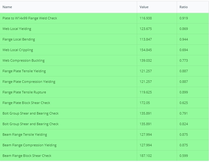
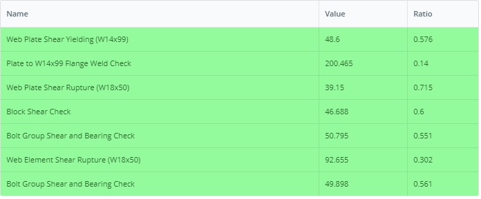
Similarly, the LRFD version example can be found in this link: Connection-Design-Report-EXAMPLE II.B-1-LRFD

References
- AISC 360 Specification Structural Steel Buildings
- AISC Design Examples v14.1 (EXAMPLE II.B-1, pages IIB-2 to 13)
- SkyCiv Connection Design Software: https://skyciv.com/structural-software/connection-design/