Base Plate Design Example using AISC 360-22 and ACI 318-19
Problem Statement
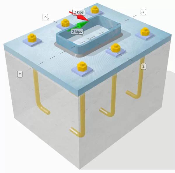
Determine whether the designed column-to-base plate connection is sufficient for a Vy=2-kip and Vz=2-kip shear loads.
Given Data
Column:
Column section: HSS7X4X5/16
Column area: 7.59 in2
Column material: A36
Base Plate:
Base plate dimensions: 12 in x 14 in
Base plate thickness: 3/4 in
Base plate material: A36
Grout:
Grout Thickness: 0.25 in
Concrete:
Concrete dimensions: 12 in x 14 in
Concrete thickness: 10 in
Concrete material: 3000 psi
Cracked or Uncracked: Cracked
Anchors:
Anchor diameter: 1/2 in
Effective embedment length: 8 in
Plate washer thickness: 0.25 in
Plate washer connection: Welded to base plate
Welds:
Weld size: 1/4 in
Filler metal classification: E70XX
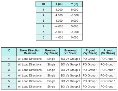
Anchor Data (from SkyCiv Calculator):
Model in SkyCiv Free Tool
Model the base plate design above using our free online tool today! No sign-up required.
Definitions
Load Path:
The design follows the recommendations of AISC Design Guide 1, 3rd Edition, and ACI 318-19. Shear loads applied to the column are transferred to the base plate through the welds, and then to the supporting concrete through the anchor rods. Friction and shear lugs are not considered in this example, as these mechanisms are not supported in the current software.
By default, the applied shear load is distributed to all anchors, either through the use of welded plate washers or by other engineering means. The load carried by each anchor is determined using the three (3) cases stated in ACI 318-19 Clause 17.7.2 and Fig. R17.7.2.1b. Each anchor then transfers the load to the supporting concrete below. The load distribution in accordance with these references is also used when checking the anchor steel shear strength to ensure continuity in the load transfer assumptions.
As an alternative, the software allows a simplified and more conservative assumption, where the entire shear load is assigned only to the anchors nearest the loaded edge. In this case, the shear capacity check is performed on these edge anchors alone.
Anchor Groups:
The SkyCiv Base Plate Design Software includes an intuitive feature that identifies which anchors are part of an anchor group for evaluating concrete shear breakout and concrete shear pryout failures.
An anchor group is defined as two or more anchors with overlapping projected resistance areas. In this case, the anchors act together, and their combined resistance is checked against the applied load on the group.
A single anchor is defined as an anchor whose projected resistance area does not overlap with any other. In this case, the anchor acts alone, and the applied shear force on that anchor is checked directly against its individual resistance.
This distinction allows the software to capture both group behavior and individual anchor performance when assessing shear-related failure modes.
Step-by-Step Calculations
Check #1: Calculate weld capacity
The first step is to calculate the total weld length available to resist shear. Since the base plate is welded along the perimeter of the column section, the total weld length is obtained by summing the welds on all sides.
\( L_{weld} = 2 \left( b_{col} – 2r_{col} – 2t_{col} \right) + 2 \left( d_{col} – 2r_{col} – 2t_{col} \right) \)
\( L_{weld} = 2 \times (4\,\text{in} – 2 \times 0.291\,\text{in} – 2 \times 0.291\,\text{in}) + 2 \times (7\,\text{in} – 2 \times 0.291\,\text{in} – 2 \times 0.291\,\text{in}) = 17.344\,\text{in} \)
Using this weld length, the applied shear forces in the y- and z-directions are divided to determine the average shear force per unit length in each direction:
\( v_{uy} = \frac{V_y}{L_{weld}} = \frac{2\,\text{kip}}{17.344\,\text{in}} = 0.11531\,\text{kip/in} \)
\( v_{uz} = \frac{V_z}{L_{weld}} = \frac{2\,\text{kip}}{17.344\,\text{in}} = 0.11531\,\text{kip/in} \)
The resultant shear demand per unit length is then determined using the square root of the sum of the squares (SRSS) method.
\( r_u = \sqrt{(v_{uy})^2 + (v_{uz})^2} \)
\( r_u = \sqrt{(0.11531\,\text{kip/in})^2 + (0.11531\,\text{kip/in})^2} = 0.16308\,\text{kip/in} \)
Next, the weld capacity is calculated using AISC 360-22 Eq. J2-4, with the directional strength coefficient taken as kds=1.0 for an HSS section. The weld capacity for a 1/4 in weld is determined as:
\( \phi r_n = \phi 0.6 F_{exx} E_w k_{ds} = 0.75 \times 0.6 \times 70\,\text{ksi} \times 0.177\,\text{in} \times 1 = 5.5755\,\text{kip/in} \)
It is also necessary to check the base metals, both the column and the base plate, using AISC 360-22 Eq. J4-4 to obtain the shear rupture strength. This gives:
\( \phi r_{nbm, col} = \phi 0.6 F_{u\_col} t_{col} = 0.75 \times 0.6 \times 58\,\text{ksi} \times 0.291\,\text{in} = 7.5951\,\text{kip/in} \)
\( \phi r_{nbm, bp} = \phi 0.6 F_{u\_bp} t_{bp} = 0.75 \times 0.6 \times 58\,\text{ksi} \times 0.75\,\text{in} = 19.575\,\text{kip/in} \)
\( \phi r_{nbm} = \min\left( \phi r_{nbm, bp},\, \phi r_{nbm, col} \right) = \min(19.575\,\text{kip/in},\, 7.5951\,\text{kip/in}) = 7.5951\,\text{kip/in} \)
Since the actual weld stress is less than both the weld metal and base metal capacities, 0.16308 kpi < 5.5755 kpi and 0.16308 kpi < 7.5951 kpi, the design weld capacity is sufficient.
Check #2: Calculate concrete breakout capacity due to Vy shear
Perpendicular Edge Capacity:
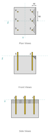
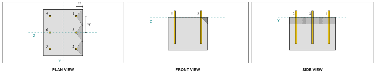
From the layout, Anchors 1 and 4 are closest to the edge and have the shortest ca1 distance. Using these ca1 values to project the failure cones, the software identified these anchors as single anchors, since their projected cones do not overlap. The support was also determined to be not a narrow member, so the ca1 distance is used directly without modification.
Let’s recall that the shear force is assumed to be distributed among all the anchors. The calculation for the Vy shear load applied to each single anchor is:
\( V_{fa\perp} = \frac{V_y}{n_a} = \frac{2\,\text{kip}}{6} = 0.33333\,\text{kip} \)
Let’s consider Anchor 1. The maximum projected area of a single anchor is calculated using ACI 318-19 Eq. 17.7.2.1.3.
\( A_{Vco} = 4.5 (c_{a1,s1})^2 = 4.5 \times (2\,\text{in})^2 = 18\,\text{in}^2 \)
The actual projected area is then determined from the width and height of the projected failure cone.
\( B_{Vc} = \min(c_{left,s1},\, 1.5c_{a1,s1}) + \min(c_{right,s1},\, 1.5c_{a1,s1}) \)
\( B_{Vc} = \min(10\,\text{in},\, 1.5 \times 2\,\text{in}) + \min(2\,\text{in},\, 1.5 \times 2\,\text{in}) = 5\,\text{in} \)
\( H_{Vc} = \min(1.5c_{a1,s1},\, t_{conc}) = \min(1.5 \times 2\,\text{in},\, 10\,\text{in}) = 3\,\text{in} \)
\( A_{Vc} = B_{Vc} H_{Vc} = 5\,\text{in} \times 3\,\text{in} = 15\,\text{in}^2 \)
The next step is to use Equations 17.7.2.2.1a and 17.7.2.2.1b to calculate the basic breakout strength of a single anchor. The governing capacity is taken as the lesser value.
\( V_{b1} = 7 \left( \frac{\min(l_e,\, 8d_a)}{d_a} \right)^{0.2} \sqrt{\frac{d_a}{\text{in}}} \lambda_a \sqrt{\frac{f’_c}{\text{psi}}} \left( \frac{c_{a1,s1}}{\text{in}} \right)^{1.5} \,\text{lbf} \)
\( V_{b1} = 7 \times \left( \frac{\min(8\,\text{in},\, 8 \times 0.5\,\text{in})}{0.5\,\text{in}} \right)^{0.2} \times \sqrt{\frac{0.5\,\text{in}}{1\,\text{in}}} \times 1 \times \sqrt{\frac{3\,\text{ksi}}{0.001\,\text{ksi}}} \times \left( \frac{2\,\text{in}}{1\,\text{in}} \right)^{1.5} \times 0.001\,\text{kip} \)
\( V_{b1} = 1.1623\,\text{kip} \)
\( V_{b2} = 9 \lambda_a \sqrt{\frac{f’_c}{\text{psi}}} \left( \frac{c_{a1,s1}}{\text{in}} \right)^{1.5} \,\text{lbf} \)
\( V_{b2} = 9 \times 1 \times \sqrt{\frac{3\,\text{ksi}}{0.001\,\text{ksi}}} \times \left( \frac{2\,\text{in}}{1\,\text{in}} \right)^{1.5} \times 0.001\,\text{kip} = 1.3943\,\text{kip} \)
\( V_b = \min(V_{b1},\, V_{b2}) = \min(1.1623\,\text{kip},\, 1.3943\,\text{kip}) = 1.1623\,\text{kip} \)
Next, the breakout capacity parameters are determined. The breakout edge effect factor is calculated according to ACI 318-19 Clause 17.7.2.4, and the thickness factor is calculated according to Clause 17.7.2.6.1.
\( \Psi_{ed,V} = \min\left(1.0,\, 0.7 + 0.3 \left( \frac{c_{a2,s1}}{1.5c_{a1,s1}} \right) \right) = \min\left(1,\, 0.7 + 0.3 \times \left( \frac{2\,\text{in}}{1.5 \times 2\,\text{in}} \right) \right) = 0.9 \)
\( \Psi_{h,V} = \max\left( \sqrt{ \frac{1.5c_{a1,s1}}{t_{conc}} },\, 1.0 \right) = \max\left( \sqrt{ \frac{1.5 \times 2\,\text{in}}{10\,\text{in}} },\, 1 \right) = 1 \)
Finally, ACI 318-19 Clause 17.7.2.1(a) is used to determine the concrete breakout capacity of a single anchor in shear. The calculated capacity for Vy shear in the perpendicular direction is 0.69 kips.
\( \phi V_{cb\perp} = \phi \left( \frac{A_{Vc}}{A_{Vco}} \right) \Psi_{ed,V} \Psi_{c,V} \Psi_{h,V} V_b \)
\( \phi V_{cb\perp} = 0.65 \times \left( \frac{15\,\text{in}^2}{18\,\text{in}^2} \right) \times 0.86 \times 1 \times 1 \times 1.1623\,\text{kip} = 0.56661\,\text{kip} \)
The calculated capacity for Vy shear in the perpendicular direction is 0.56 kips.
Parallel Edge Capacity:
Failure along the edge parallel to the load is also possible in this scenario, so the concrete breakout capacity for the parallel edge must be determined. The anchors or anchor group considered are those aligned with the parallel edge. Consequently, the ca1 edge distance is measured from the anchor to the edge along the Z-direction. Based on the figure below, the failure cone projections overlap; therefore, the anchors are treated as a group.
Case 1:
Case 2:
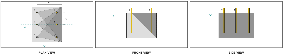
We refer to ACI 318-19 Fig. R17.7.2.1b for the different cases used when evaluating anchor groups. In this base plate design, welded plate washers are specifically used. Therefore, only Case 2 is checked.
The required load for the anchor group in Case 2 is taken as the total shear load.
\( V_{fa\parallel,case2} = V_y = 2\,\text{kip} \)
In calculating the capacity for the Case 2 failure, the anchors considered are the rear anchors. As a result, the ca1 edge distance is measured from the rear anchor group to the failure edge.
With this ca1 distance and edge orientation, it must be verified whether the support qualifies as a narrow member. Following ACI 318-19 Clause 17.7.2.1.2, the SkyCiv Base Plate software identified the support as narrow. Therefore, the modified ca1 distance is used, which is calculated to be 6.667 in.
The same steps as in the perpendicular case are followed: calculating the projected failure areas, the basic single-anchor breakout strength, and the breakout parameters. The calculated values for each step are shown below.
\( A_{Vco} = 4.5 (c_{‘a1,g2})^2 = 4.5 \times (6.6667\,\text{in})^2 = 200\,\text{in}^2 \)
\( A_{Vc} = B_{Vc} H_{Vc} = 14\,\text{in} \times 10\,\text{in} = 140\,\text{in}^2 \)
\( V_{b1} = 7.0733\,\text{kip} \)
\( V_{b2} = 8.4853\,\text{kip} \)
\( V_b = \min(V_{b1},\, V_{b2}) = \min(7.0733\,\text{kip},\, 8.4853\,\text{kip}) = 7.0733\,\text{kip} \)
\( \Psi_{ed,V} = 1.0 \)
\( \Psi_{h,V} = 1.0 \)
The equation for the parallel edge capacity differs from the perpendicular edge capacity. ACI 318-19 Clause 17.7.2.1(c) is applied, where the breakout equation is multiplied by 2.
\( \phi V_{cbg\parallel} = 2 \phi \left( \frac{A_{Vc}}{A_{Vco}} \right) \Psi_{ed,V} \Psi_{c,V} \Psi_{h,V} V_b \)
\( \phi V_{cbg\parallel} = 2 \times 0.65 \times \left( \frac{140\,\text{in}^2}{200\text{in}^2} \right) \times 1 \times 1 \times 1 \times 7.0733\,\text{kip} = 6.4367\,\text{kip} \)
The calculated capacity for Vy shear in the parallel direction is 6.43 kips.
We now assess the perpendicular and parallel failures separately.
- For the perpendicular edge failure, since 0.33 kip < 0.56 kip, the design concrete shear breakout capacity is sufficient.
- For the parallel edge failure, since 2 kip < 6.43 kip, the design concrete shear breakout capacity is sufficient.
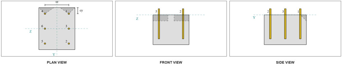
Check #3: Calculate concrete breakout capacity due to Vz shear
The base plate is also subjected to Vz shear, so the failure edges perpendicular and parallel to the Vz shear must be checked. Using the same approach, the perpendicular and parallel capacities are calculated as 2.45 kips and 1.26 kips, respectively.
Perpendicular Edge:
Parallel Edge:
These capacities are then compared to the required strengths.
- For the perpendicular edge failure, since 2 kip < 2.45 kip, the concrete shear breakout capacity is sufficient.
- For the parallel edge failure, since 0.33 kip < 1.26 kip, the concrete shear breakout capacity is sufficient.
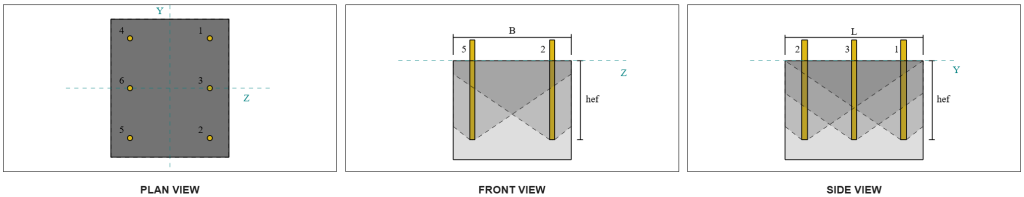
Check #4: Calculate concrete pryout capacity
The concrete cone for pryout failure is the same cone used in the tensile breakout check. To calculate the shear pryout capacity, the nominal tensile breakout strength of the single anchors or anchor group must first be determined. The detailed calculations for the tensile breakout check are already covered in the SkyCiv Design Examples for Tension Load.
It is important to note that the anchor group determination for shear pryout is different from that for shear breakout. Therefore, the anchors in the design must still be checked to determine whether they act as a group or as single anchors against the shear pryout failure. The classification of the support as a narrow section must also be verified and should follow the same conditions used for tension breakout.
From the SkyCiv calculations, the nominal tensile breakout strength of the anchor group is 12.772 kips. With a pryout factor of kcp=2, the design pryout capacity is:
\( \phi V_{cpg} = \phi k_{cp} N_{cbg} = 0.65 \times 2 \times 12.772 \,\text{kip} = 16.604\,\text{kip} \)
The required strength is the resultant of the applied shear loads. Since all anchors belong to a single group, the total resultant shear is assigned to the group.
\( V_{ua} = \sqrt{(V_y)^2 + (V_z)^2} = \sqrt{(2\,\text{kip})^2 + (2\,\text{kip})^2} = 2.8284\,\text{kip} \)
\( V_{ua} = \left( \frac{V_{ua}}{n_a} \right) n_{a,g1} = \left( \frac{2.8284\,\text{kip}}{6} \right) \times 6 = 2.8284\,\text{kip} \)
Since the total shear load is less than anchor group capacity, 2.82 kips < 18.976 kips, the design pryout capacity is sufficient.
Check #5: Calculate anchor rod shear capacity
Recall that in this design example, shear is distributed to all anchors. The total shear load per anchor is therefore the resultant of its share of the Vy load and its share of the Vz load.
\( v_{ua,y} = \frac{V_y}{n_a} = \frac{2\,\text{kip}}{6} = 0.33333\,\text{kip} \)
\( v_{ua,z} = \frac{V_z}{n_a} = \frac{2\,\text{kip}}{6} = 0.33333\,\text{kip} \)
\( V_{ua} = \sqrt{(v_{ua,y})^2 + (v_{ua,z})^2} \)
\( V_{ua} = \sqrt{(0.33333\,\text{kip})^2 + (0.33333\,\text{kip})^2} = 0.4714\,\text{kip} \)
This gives the shear stress on the anchor rod as:
\( f_v = \frac{V_{ua}}{A_{rod}} = \frac{0.4714\,\text{kip}}{0.19635\,\text{in}^2} = 2.4008\,\text{ksi} \)
Because a plate washer is present, an eccentric shear load is induced in the anchor rod. The eccentricity is taken as half of the distance measured from the top of the concrete support to the center of the plate washer, accounting for the thickness of the base plate. Refer to AISC Design Guide 1, 3rd Edition Section 4.3.3.
\( e = 0.5 \left( \frac{t_{pw}}{2} + t_{bp} \right) = 0.5 \times \left( \frac{0.25\,\text{in}}{2} + 0.75\,\text{in} \right) = 0.4375\,\text{in} \)
The moment from the eccentric shear is then expressed as an axial stress in the anchor rod. Using the section modulus, the axial stress due to this moment is calculated as:
\( Z_{rod} = \frac{\pi}{32} (d_a)^3 = \frac{\pi}{32} \times (0.5\,\text{in})^3 = 0.012272\,\text{in}^3 \)
\( f_t = \frac{V_{ua} e}{Z_{rod}} = \frac{0.4714\,\text{kip} \times 0.4375\,\text{in}}{0.012272\,\text{in}^3} = 16.806\,\text{ksi} \)
ACI Anchor Rod Shear Capacity:
Following ACI 318-19 Clause 17.7.1, the design strength is then determined. A 0.8 reduction factor is applied due to the presence of grout pads. The design capacity is therefore:
\( \phi V_{sa,aci} = 0.8 \phi 0.6 A_{se,v} f_{uta} = 0.8 \times 0.65 \times 0.6 \times 0.1419\text{in}^2 \times 90\text{ksi} = 3.9845\text{kip} \)
As an alternative, the SkyCiv Base Plate software allows the 0.8 simplification to be disabled, and use the actual grout pad thickness in the calculations. In this case, the total eccentricity includes the grout pad, and the combined shear and axial strength is determined in accordance with AISC provisions.
AISC Anchor Rod Shear Capacity:
First, the nominal shear and tensile stresses are determined for an A325 rod.
\( F_{nv} = 0.45 F_{u,anc} = 0.45 \times 120\ \text{ksi} = 54\ \text{ksi} \)
\( F_{nt} = 0.75 F_{u,anc} = 0.75 \times 120\ \text{ksi} = 90\ \text{ksi} \)
The AISC method uses AISC 360-22 Eq. J3-3a, which may be expressed to include the effects of axial stress. This is carried out as follows.
\( F’_{nv} = \min \left( 1.3 F_{nv} – \left( \frac{F_{nv}}{\phi F_{nt}} \right) f_t,\; F_{nv} \right) \)
\( F’_{nv} = \min \left( 1.3 \times 54\ \text{ksi} – \left( \frac{54\ \text{ksi}}{0.75 \times 90\ \text{ksi}} \right) \times 16.806\ \text{ksi},\; 54\ \text{ksi} \right) = 54\ \text{ksi} \)
The design shear capacity from the AISC method is then calculated as:
\( \phi R_{n,\mathrm{aisc}} = \phi F’_{nv} A_{rod} = 0.75 \times 54\ \text{ksi} \times 0.19635\ \text{in}^2 = 7.9522\)
To ensure both methods are covered, the governing capacity is taken as the lesser of the two, which is 3.98 kip.
\( \phi V_n = \min \left( \phi V_{sa,aci},\; \phi R_{n,\mathrm{aisc}} \right) = \min (3.9845\ \text{kip},\; 7.9522\ \text{kip}) = 3.9845\ \text{kip} \)
Since the shear load per anchor rod is less than the governing anchor rod capacity in shear, 0.47 kip < 3.98 kip, the design anchor rod shear capacity is sufficient.
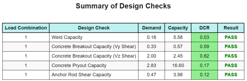
Design Summary
The SkyCiv Base Plate Design software can automatically generate a step-by-step calculation report for this design example. It also provides a summary of the checks performed and their resulting ratios, making the information easy to understand at a glance. Below is a sample summary table, which is included in the report.
SkyCiv Sample Report
See the level of detail and clarity you can expect from a SkyCiv Base Plate Design Report. The report includes all key design checks, equations, and results presented in a clear and easy-to-read format. It is fully compliant with design standards. Click below to view a sample report generated using the SkyCiv Base Plate Calculator.
Purchase Base Plate Software
Purchase the full version of the base plate design module on its own without any other SkyCiv modules. This gives you a full set of results for Base Plate Design, including detailed reports and more functionality.